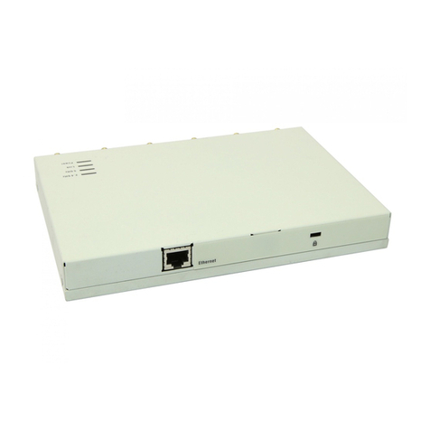
Belair 100SN User manual

BelAir100SN
Page 1 of 75
Release: 11.0
Document Date: May 18, 2010
Document Number: BDTK11001-A01
Document Status: Preliminary
Security Status: Confidential
Customer Support: 613-254-7070
1-877-BelAir1 (235-2471)
techsupport@belairnetworks.com
© Copyright 2010 by BelAir Networks.
The information contained in this document is confidential and proprietary to BelAir Networks. Errors and Omissions Excepted.
Specification may be subject to change. All trademarks are the property of their respective owners.
Protected by U.S. Patents: 7,171,223, 7,164,667, 7,154,356, 7,030,712 and D501,195. Patents pending in the U.S. and other countries.
BelAir Networks, the BelAir Logo, BelAir200, BelAir100, BelAir100S, BelAir100C, BelAir100T, BelAir20, BelAir100i, BelAir100SN, BelAir100N, BelView and BelView
NMS are trademarks of BelAir Networks Inc.
BelAir100SN
Installation Guide
PRODUCT MODEL: BelAir100S

May 18, 2010 Confidential Page 2 of 75
Document Number BDTK11001-A01 Preliminary
BelAir100SN Installation Guide Contents
Contents
About This Document . . . . . . . . . . . . . . . . . . . . . . . . . . . . . . . . . . . 3
BelAir100SN Physical Description . . . . . . . . . . . . . . . . . . . . . . . . . . 4
Infrastructure Requirements for the BelAir100SN . . . . . . . . . . . . . 6
Mounting Options. . . . . . . . . . . . . . . . . . . . . . . . . . . . . . . . . . . . . . 19
Before You Install the BelAir100SN. . . . . . . . . . . . . . . . . . . . . . . . 21
Strand mounting the BelAir100SN with Omni-directional Antennas
29
Strand mounting the BelAir100SN with Directional Antennas. . . 36
Pedestal Installation of the BelAir100SN . . . . . . . . . . . . . . . . . . . . 42
Commissioning BelAir100SN Units . . . . . . . . . . . . . . . . . . . . . . . . 53
Troubleshooting . . . . . . . . . . . . . . . . . . . . . . . . . . . . . . . . . . . . . . . 55
For More Information. . . . . . . . . . . . . . . . . . . . . . . . . . . . . . . . . . . 58
Technical Support. . . . . . . . . . . . . . . . . . . . . . . . . . . . . . . . . . . . . . 60
Conformity and Regulatory Statements. . . . . . . . . . . . . . . . . . . . . 61
Detailed Table of Contents . . . . . . . . . . . . . . . . . . . . . . . . . . . . . . 71

BelAir100SN Installation Guide About This Document
May 18, 2010 Confidential Page 3 of 75
Document Number BDTK11001-A01 Preliminary
About This Document
This guide provides the information you need to physically install the
BelAir100SN™.
Typo graph ica l
Conventions
This document uses the following typographical conventions:
• Text in < > indicates a parameter required as input for a CLI command;
for example, < IP address >
• Text in [ ] indicates optional parameters for a CLI command.
• Text in { } refers to a list of possible entries with | as the separator.
• Parameters in ( ) indicate that at least one of the parameters must entered.
Related
Documentation
The following titles are BelAir reference documents:
•
BelAir100SN User Guide
•
BelAir100SN Troubleshooting Guide

BelAir100SN Installation Guide BelAir100SN Physical Description
May 18, 2010 Confidential Page 4 of 75
Document Number BDTK11001-A01 Preliminary
BelAir100SN Physical Description
This chapter provides a physical description of the BelAir100SN and its
associated hardware.
The BelAir100SN is an integrated radio product requiring only a connection to
a suitable power source.
Without antennas and strand mounting brackets, the BelAir100SN is
approximately 8.5 inches (21.6 cm) high, 15.5 inches (39.4 cm) wide and
7 inches (17.8 cm) deep. It weighs 29 lbs (13.2 kg). See Figure 1 on page 4.
Figure 1: BelAir100SN Unit without Antennas
AC Power Supply
Specifications
The BelAir100SN accepts an AC input power in the range of 40 VAC to
90 VAC -0% +10% with a quasi-square wave. The frequency range is 47 to
63 Hz. The typical current draw is less than 1 A.

BelAir100SN Installation Guide BelAir100SN Physical Description
May 18, 2010 Confidential Page 5 of 75
Document Number BDTK11001-A01 Preliminary
AC Power Source
The BelAir100SN draws its AC power from plant power through its KS
threaded power interface. The BelAir100SN includes an industry standard GRS
connector that mates with a coaxial cable terminator with a KS interface for
cables of the following sizes: 0.412, 0.500, 0.625, 0.750, 0.875 and 1.000 inches.
A KS to F-type adapter can also be used. The GRS connector provides two
points of contact for a robust AC power connection.

BelAir100SN Installation Guide Infrastructure Requirements for the BelAir100SN
May 18, 2010 Confidential Page 6 of 75
Document Number BDTK11001-A01 Preliminary
Infrastructure Requirements for the BelAir100SN
This section describes the infrastructure that is required at the location where
BelAir100SN units are installed:
•“Protective Earth Ground” on page 6
•“AC Power” on page 7
•“Lightning Protection” on page 9
•“DOCSIS” on page 9
•“Ethernet” on page 13
•“Antenna Type and Placement” on page 14
Any identified specific third party parts are recommendations or examples only.
Substitution of equivalent parts is permitted. (If you are unsure of the
equivalency of a certain component, contact BelAir Networks.)
Protective Earth
Ground
For safety and functional operation, each BelAir unit must be connected to a
reliable earth ground before electrical power is applied to it. Special attention
should be made when installing the ground and connection of the ground wire
must follow local and national wiring codes. If multiple BelAir units are installed
at a single location, then each BelAir unit must be connected to the same
ground point.
The BelAir100SN is powered by the coaxial cable and is considered grounded
where connected to the cable shield, as required by US National Electric Code,
section 820-41. In addition, installers may wish to bond the BelAir100SN
ground to the messenger wire. To do so, the additional connection is to a
1/4 inch (approx. 6 mm) ground terminal with screw. Figure 2 shows the
location of the ground point and the ground terminal. Installers should follow
normal practices when grounding the unit. Installers should verify that all
grounding requirements listed in this document have been met.
Warning — Protective Earth Ground
Failure to connect the protective earth ground can result in a
shock hazard.

BelAir100SN Installation Guide Infrastructure Requirements for the BelAir100SN
May 18, 2010 Confidential Page 7 of 75
Document Number BDTK11001-A01 Preliminary
Figure 2: BelAir100SN Ground Point
AC Power The BelAir100SN accepts power in the range of 40 VAC to 90 VAC (-0% to
+10%) from a quasi-square wave cable UPS power supply. The BelAir100SN
also requires that the cable UPS power supply limits its output current to 30 A.
Installers must ensure that the supplied power meets these requirements.
The BelAir100SN contains a permanently attached female KS threaded power
interface (Corning Gilbert part number G-EXT-1.5-SC-T). This connector can
connect with an industry standard GRS KS male threaded connector to accept
cables of the following sizes: 0.412, 0.500, 0.625, 0.750, 0.875 and 1.000 inches.
The mating connector accepts 0.065-inch to 0.75-inch pins trimmed to
0.5 inches. Figure 3 shows the female KS connector.
Ground point
through cable
connector and shield
Ground terminal
through 1/4 inch
screw

BelAir100SN Installation Guide Infrastructure Requirements for the BelAir100SN
May 18, 2010 Confidential Page 8 of 75
Document Number BDTK11001-A01 Preliminary
Figure 3: KS Connector
A KS to F-type adapter can also be used. See Figure 4. The customer is
responsible for supplying the appropriate coaxial cable terminator with a KS
male interface or the equivalent KS to F-type adapter. BelAir Networks
recommends using Corning Gilbert part number GF-625-CH-S-T which is
designed to work well with the BelAir100SN female KS threaded power
interface.
Figure 4: KS to F-type Adapter
BelAir100SN

BelAir100SN Installation Guide Infrastructure Requirements for the BelAir100SN
May 18, 2010 Confidential Page 9 of 75
Document Number BDTK11001-A01 Preliminary
Professional installers with appropriate credentials and experience are
responsible for installing coaxial cable terminator or the KS to F-type adapter
onto the cable power supply using industry and corporate standard procedures.
Lightning
Protection
BelAir units are not designed to survive a direct lightning hit. However, they are
intended to withstand the voltage and current surges induced from nearby
lightning activity.
The BelAir100SN is designed to sustain multiple 6 kV/3 kA lightning surges
without damage or loss of operation. The BelAir100SN does not require
lightning protection except when an external antenna is installed more than
3 feet (approx. 1 m) from the unit.
In this case, you must use lightning arrestors to protect the external antennas
ports. When lightning arrestors are used, they should be located within 3 feet
(approx. 1 m) of the BelAir100SN unit and must be grounded to both the unit
and protective earth ground. The N-type connector may be used to complete
the ground connection.
DOCSIS BelAir100SN units contain an embedded Hitron DOCSIS 3.0 cable modem,
model number BRG-35502, providing connectivity to a host network, such as
the Internet.
The cable modem is accessed directly through the GRS connector that is used
for both power input and as a DOCSIS RF interface. The cable modem is fully
DOCSIS 3.0 compliant and designed for use with 75 ohm cables.
The standard input range of a cable modem is -15 dBmV to +15 dBmV for
DOCSIS 3 and 17 dBmV for DOCSIS 3. The BelAir100SN implements
independent 0 to 20 dB digital attenuators in both upstream and downstream
paths.
Cable Modem Receiver Specifications
Tab l e 1 shows the cable modem receiver characteristics.
Table 1: Cable Modem Receiver Characteristics
Characteristic DOCSIS 2.0 DOCSIS 3.0
Demodulation 64/256 QAM

BelAir100SN Installation Guide Infrastructure Requirements for the BelAir100SN
May 18, 2010 Confidential Page 10 of 75
Document Number BDTK11001-A01 Preliminary
Cable Modem Transmitter Specifications
Tab l e 2 shows the cable modem transmitter characteristics.
Maximum speed • 38 Mbps (64 QAM) / 43 Mbps
(256 QAM) DOCSIS
• 5120 kbps / 10 Mbps (QPSK /
16 QAM) DOCSIS
• 41.4 Mbps (64 QAM) /
55.2 Mbps(256 QAM) EuroDOCSIS
• +171.52 (+152) Mbps with four DS
channel bounding (DOCSIS)
• +222.48 (+200) Mbps with four DS
channel bounding (EuroDOCSIS)
Frequency range • 91 to 857 MHz ±30 kHz (Center)
DOCSIS
• 108 to 862 MHz ±30 kHz (Edge)
EuroDOCSIS
• 93 to 767 MHz ±30 kHz (Center)
DOCSIS-J
• 50 MHz to 1002 MHz (DOCSIS)
Bandwidth 6 MHz (DOCSIS, DOCSIS-J)
8 MHz (EuroDOCSIS)
6/8 MHz (DOCSIS and EuroDOCSIS dual mode)
Table 1: Cable Modem Receiver Characteristics (Continued)
Characteristic DOCSIS 2.0 DOCSIS 3.0
Table 2: Cable Modem Receiver Characteristics
Characteristic DOCSIS 2.0 DOCSIS 3.0
Modulation TDMA: QPSK, 8 QAM, 16 QAM,
32 QAM, 64 QAM
S-CDMA: QPSK, 8 QAM, 16 QAM, 32
QAM, 64 QAM, 128 QAM
QPSK, 8 QAM, 16 QAM, 32 QAM,
64 QAM and 128 QAM
Maximum speed 320, 640, 1280, 2560, 5120 kbps
(QPSK)
640, 1280, 2560, 5120, 10240 kbps (16
QAM)
+122.88 (+108) Mbps with four US
channel bounding
(DOCSIS / EuroDOCSIS)

BelAir100SN Installation Guide Infrastructure Requirements for the BelAir100SN
May 18, 2010 Confidential Page 11 of 75
Document Number BDTK11001-A01 Preliminary
Frequency range • 5 to 42 MHz (edge to edge)
DOCSIS
• 5 to 65 MHz (edge to edge)
EuroDOCSIS / Dual
• 5 to 55 MHz (edge to edge)
DOCSIS-J
• 5 to 42 MHz edge to edge or
5 to 85 MHz edge to edge (DOCSIS)
• Optional upstream frequency range
5-85 MHz; Extended Upstream
Frequency Range
Bandwidth TDMA: 200, 400, 800, 1600, 3200 and
6400 kHz
S-CDMA: 1600, 3200 and 6400 kHz
TDMA: 1600, 3200 and 6400 kHz
S-CDMA: 1600, 3200 and 6400 kHz
Optional pre-3.0-DOCSIS operation,
TDMA: 200, 400 and 800 kHz
Signal level TDMA:
+8 to +54 dBmV (32 QAM, 64 QAM)
+8 to +55 dBmV (8QAM, 16QAM)
+8 to +58 dBmV (QPSK)
S-CDMA:
+8 to +53 dBmV (all modulations)
One US Channel in TCS: See Table 3 on
page 11.
Two US Channels in TCS: See Table 4 on
page 12.
Three or Four US Channels in TCS: See
Table 5 on page 12.
Output level of cable modem can be automatically controlled by CMTS through
power ranging function in 1 dB steps.
Output return loss > 6 dB (5 to 42 MHz) and
(91 ~ 857 MHz)
>6 dB (across the selected upstream
frequency range 5 to 42 MHz or 5 to
85 MHz).
> 6 dB (108 to 870 MHz or 108 to 1002
MHz if CM center frequency ranges up
to 999 MHz)
Table 2: Cable Modem Receiver Characteristics (Continued)
Characteristic DOCSIS 2.0 DOCSIS 3.0
Table 3: Cable Modem Output Levels (One US Channel in TCS)
TDMA Modulation Output Level
QPSK Pmin to +61 dBmV
8 QAM, 16 QAM Pmin to +58 dBmV
32 QAM, 64 QAM Pmin to +57 dBmV

BelAir100SN Installation Guide Infrastructure Requirements for the BelAir100SN
May 18, 2010 Confidential Page 12 of 75
Document Number BDTK11001-A01 Preliminary
S-CDMA Modulation Output Level
All Pmin to +56 dBmV
where:
Pmin = +17 dBmV, 1280 kHz modulation rate
Pmin = +20 dBmV, 2560 kHz modulation rate
Pmin = +23 dBmV, 5120 kHz modulation rate
Table 4: Cable Modem Output Levels (Two US Channel in TCS)
TDMA Modulation Output Level
QPSK Pmin to +58 dBmV
8 QAM, 16 QAM Pmin to +55 dBmV
32 QAM, 64 QAM Pmin to +54 dBmV
S-CDMA Modulation Output Level
All Pmin to +53 dBmV
where:
Pmin = +17 dBmV, 1280 kHz modulation rate
Pmin = +20 dBmV, 2560 kHz modulation rate
Pmin = +23 dBmV, 5120 kHz modulation rate
Table 5: Cable Modem Output Levels (Three or Four US Channels in TCS)
TDMA Modulation Output Level
QPSK Pmin to +55 dBmV
8 QAM, 16 QAM Pmin to +52 dBmV
32 QAM, 64 QAM Pmin to +51 dBmV
S-CDMA Modulation Output Level
All Pmin to +53 dBmV
Table 3: Cable Modem Output Levels (One US Channel in TCS) (Continued)
TDMA Modulation Output Level

BelAir100SN Installation Guide Infrastructure Requirements for the BelAir100SN
May 18, 2010 Confidential Page 13 of 75
Document Number BDTK11001-A01 Preliminary
Ethernet The BelAir unit’s has a 10/100/1000 BASE-TX Ethernet port that is compliant
to the IEEE 802.3 standard. This port has a reach of 320 feet (approx. 100 m)
using standard Category 5 twisted pair.
The Ethernet port uses a shielded RJ45 connector. The pinout is given in
Tab l e 6 and Figure 5 on page 14.
where:
Pmin = +17 dBmV, 1280 kHz modulation rate
Pmin = +20 dBmV, 2560 kHz modulation rate
Pmin = +23 dBmV, 5120 kHz modulation rate
Table 5: Cable Modem Output Levels (Three or Four US Channels in TCS)
TDMA Modulation Output Level
Table 6: Ethernet Pinout for BelAir100SN
Contact Function
1 Transmit 0 +
2 Transmit 0 -
3 Receive 0 +
4 Transmit 1 +
5 Transmit 1 -
6 Receive 0 -
7 Receive 1 +
8 Receive 1 -

BelAir100SN Installation Guide Infrastructure Requirements for the BelAir100SN
May 18, 2010 Confidential Page 14 of 75
Document Number BDTK11001-A01 Preliminary
Figure 5: Ethernet Pinout
The internal Ethernet interface is protected against surges induced by lightning.
It is strongly recommended to use shielded category 5e wire (such as Belden®
7929 Datatuff®) to provide additional lightning protection.
Antenna Type and
Placement
Proper antenna placement, orientation and selection are critical factors in
maximizing network performance. The BelAir antennas are typically placed
between 16 feet and 32 feet (approx. 5 m and 10 m) above ground level;
although alternate installations can be used. Additionally, directional antennas
should be located with clear lines of sight to adjacent equipment in the system
and free from obstruction by buildings, foliage and passing traffic.
Note 1: If a BelAir unit uses external antennas and is mounted on a structure
that has frequent direct lightning strikes, such as cellular telephone or
water tower, then use ¼ wavelength stubs to avoid the effects of the
lightning strikes.
Note 2: If a BelAir unit uses 5 GHz omni-directional antennas, BelAir
Networks recommends that you mount it vertically up; that is, with its
base is pointing down and its top is pointing up.
In addition, antennas that are mounted with a BelAir100SN must be located at
least 18 inches (approx. 45.7 cm) from the nearest pole to avoid shadowing
effects.

BelAir100SN Installation Guide Infrastructure Requirements for the BelAir100SN
May 18, 2010 Confidential Page 15 of 75
Document Number BDTK11001-A01 Preliminary
BelAir100SN Omni-directional Antenna Placement Options
Omni-directional antennas can be mounted in any of the four top corners on
the BelAir100SN unit.
Warning — Use BelAir Antennas Only
Only antennas approved by BelAir Networks may be used in
conjunction with BelAir products. Contact BelAir Networks
for an up-to-date list of available approved antennas. Use of
any other antenna may exceed regulatory requirements and
void the operator’s right to operate the radio equipment. Any
product damage caused by the use of non-BelAir approved
antennas will not be covered under BelAir’s product warranty.
Warning — Restricted Antenna Access
Installers must ensure the BelAir product is mounted in such a
manner and in such a location that access to the antennas by
the general population is minimized. During normal operation,
access to the antennas by the general population should be
limited to 8.1 inches (20.6 cm) for units with the following
radios and antennas:
• DRU radios with BelAir antennas up to 15 dBi
During normal operation, access to the antennas by the
general population should be limited to 16.5 inches (42 cm) for
units with the following radios and antennas:
• DRU radios with BelAir antennas up to 18 dBi
Warning — Minimum Distance to Local AC Power
When installing a strand mounted unit, installers must ensure
the BelAir product and external antennas maintain at all times
at least the minimum safety distance away from any electrical
power distribution cables on the pole according to local
electrical code.

BelAir100SN Installation Guide Infrastructure Requirements for the BelAir100SN
May 18, 2010 Confidential Page 16 of 75
Document Number BDTK11001-A01 Preliminary
However, BelAir Networks recommends that you install both your antennas on
the same vertical plane closest to the road. See Figure 6. This give maximum
coverage to the vehicles on the road.
Figure 6: Recommended Omni-directional Antenna Placement
BelAir100SN Directional Antenna Placement Options
Directional backhaul antennas are oriented vertically while directional access
antennas are oriented horizontally. See Figure 7 on page 17.
GRS
Connector Left Side
Connector
Field
Strand
Clamps
Antennas and
Antenna
Brackets
Road
Direction

BelAir100SN Installation Guide Infrastructure Requirements for the BelAir100SN
May 18, 2010 Confidential Page 17 of 75
Document Number BDTK11001-A01 Preliminary
Figure 7: Horizontal and Vertical Directional Antennas
Directional antennas can be mounted at the four corners of the BelAir100SN.
Each location can accept either a directional access antenna or a directional
backhaul antenna. Refer to Figure 8 on page 18. As well each antenna can be
rotated 90 degrees horizontally.
Note: The size of the GRS connector in the rear left corner of the unit may
prevent full rotation of a directional backhaul antenna mounted at that
location. If this is an issue, try mounting the backhaul antenna in
another corner of the unit.
Vertical backhaul antenna
with bracket arm and
retaining screws
Horizontal access antenna
with bracket arm and
retaining screws

BelAir100SN Installation Guide Mounting Options
May 18, 2010 Confidential Page 19 of 75
Document Number BDTK11001-A01 Preliminary
Mounting Options
This chapter describes the various ways that a BelAir100SN unit can be
mounted, including:
•“Strand Mounting” on page 19
•“Pedestal Installations” on page 19
Any identified specific third party parts are recommendations or examples only.
Substitution of equivalent parts is permitted. (If you are unsure of the
equivalency of a certain component, contact BelAir Networks.)
Liability
Regardless of the mounting option you choose, the recommendations made in
this document are for reference only. The customer is responsible for ensuring
that installations are carried out in compliance with national, regional and local
building codes, and any applicable electrical safety authority standards.
Always follow the manufacturer’s recommendations when using third party
installation hardware.
Always maintain safe working practices and use appropriate personal protective
equipment.
Strand Mounting The BelAir100SN is designed to be clamped on stranded messenger wire
between 1/4 and 3/8 inch (approx. 6 and 10 mm) diameter.
A BelAir100SN unit must be mounted at least 18 inches (approx. 45.7 cm) from
the nearest pole to avoid shadowing effects.
For details, see:
•“Strand mounting the BelAir100SN with Omni-directional Antennas” on
page 29.
•“Strand mounting the BelAir100SN with Directional Antennas” on page 36
Pedestal
Installations
With the BelAir Pedestal Mounting Kit (BNCKG0114) and the BelAir Pedestal
Antenna Kit, you can mount the BelAir100SN in a Channell Signature Pedestal
Housing (SPH-1212). The installation works with the B1 bracket and B2 bracket
(preferred). The SPH1212 pedestal measures 12 inches x 12 inches x 32 inches.
Figure 9 on page 20 shows SPH1212 pedestal with the installed BelAir100SN.
This manual suits for next models
1
Table of contents
Other Belair Wireless Access Point manuals


