Belanger Top Wheel Mix & Match User manual

Top Wheel Mix & Match
1MANUAL749 Rev12
Top Wheel Mix & Match


Belanger Equipment Owner’s Manual
Top Wheel Mix and Match
Copyright 2020
Belanger, Inc®
This manual and the accompanying equipment are protected by United States trademark, copyright, and patent laws. You
may make one copy of this manual. Do not make additional copies of this manual or electronically transmit it in any form
whatsoever, in whole or in part, without the prior written permission of Belanger, Inc.®
The registered trademarks used in this document are the property of their respective owners. The use of such trademarks is
for reference purposes only and does not imply sponsorship or approval of Belanger, Inc.®by these companies or any
companies affiliated with their respective owners.

CURRENT REVISION LOG
Belanger, Inc. * 1001 Doheny Ct. * Northville, MI 48167 * Ph (248) 349-7010 * Fax (248) 380-9681 1MANUL749
Rev
Release
Date
Page
Description
11
04/10/2020
Manual
Revised manual to conform to CE requirements.
Manual
Updated Front Cover, Back Cover and Belanger®Logo
3
Updated Belanger Limited Warranty
39
Added note to maintain the vehicle washing weight of the Top
Wheel (per Change Request #1)
39-41
Changed title from Counterweight and Covers to Counterweight
Installation and added subtitle Counterweight Configuration
47
Added note about altering counterweights and that too much vehicle
penetration can cause damage to vehicles or the wash equipment
(per Change Request #1)
49
Added weekly procedure: Check penetration weight of the Top
Wheel. Add or remove counterweight as needed (per Change
Request #1)
70
Removed image of assembled cylinder and the following note
105835: Cylinder Assembly Complete (per Change Request #3)
72
Changed part number 1AIRLN165 to 1AIRLN250
12
10/09/2020
68
Changed Gearbox Assembly number from 1GEABX-AS985 to
112285 (per ECN #5131)
Back
Cover
Updated Back Cover with correct phone number

TOP WHEELMix and Match
1MANUL749 Belanger, Inc. * 1001 Doheny Ct. * Northville, MI 48167 * Ph (248) 349-7010 * Fax (248) 380-9681 1
Table of Contents
Belanger Incorporated Limited Warranty...................................................................3
Introduction..................................................................................................................4
IMPORTANT Safety Information –MUST READ.................................................................................................... 4
Operational Warning ............................................................................................................................................... 8
Environmental Parameters...................................................................................................................................... 9
Safeguards .............................................................................................................................................................. 9
Reasonable and Foreseeable Misuse..................................................................................................................... 9
Do’s and Do Not’s ................................................................................................................................................. 10
Description of Top Wheel ...................................................................................................................................... 11
Before You Get Started ......................................................................................................................................... 12
Specifications............................................................................................................13
Requirements ........................................................................................................................................................ 13
Output.................................................................................................................................................................... 13
General Dimensions.............................................................................................................................................. 14
Installation..................................................................................................................15
Hub Assembly ....................................................................................................................................................... 15
Neo-Tex™ Media Hub Overview.........................................................................................................................................15
Parts Required.....................................................................................................................................................................15
Neo-Tex™ Hub Assembly ...................................................................................................................................................16
Whisper Wheel Hub Overview (North American Option) ....................................................................................................19
Parts Required and Relevant Note......................................................................................................................................19
Whisper Wheel Hub Assembly (North American Option)....................................................................................................20
Frame Assembly ................................................................................................................................................... 21
Securing Drive Shaft Assembly to the Driver Side Arm (Electric Drive)..............................................................................21
Securing Drive Shaft and Hydraulic Motor Assembly to the Driver Side Arm .....................................................................23
Securing the Arms to the Hub .............................................................................................................................................25
Installing the Crossbeam ..................................................................................................................................................... 26
Attaching the Legs...............................................................................................................................................................27
Tunnel Placement Overview................................................................................................................................................28
Erecting the Frame ..............................................................................................................................................................29
Motor/Gearbox Installation: Electric Drive Neo-Tex™/ Whisper Media ..............................................................................30
Motor/Gearbox Installation: Electric Drive Brush Wheel .....................................................................................................32
Posi-Stops Installation .........................................................................................................................................................33
Shock Assembly ..................................................................................................................................................................34
Auto Retract Option Installation (if applicable) ...................................................................................................... 35
Parts Identification ...............................................................................................................................................................36
Wiring for Optional Auto Retract..........................................................................................................................................37
Air Panel Installation and Photo-Eye Utility Connection (if applicable) ...............................................................................38
Counterweight Installation ..................................................................................................................................... 39
Things to Know....................................................................................................................................................................39
Counterweight Configuration ...............................................................................................................................................39
End Caps............................................................................................................................................................... 42
Utility Connections................................................................................................................................................. 43
Water Feeds ........................................................................................................................................................................43
Electric Drive Motor Feed ....................................................................................................................................................44
Hydraulic Drive Motor Feed (North American Option).........................................................................................................45

TOP WHEELMix and Match
2Belanger, Inc. * 1001 Doheny Ct. * Northville, MI 48167 * Ph (248) 349-7010 * Fax (248) 380-9681 1MANUL749
Table of Contents
Startup........................................................................................................................ 47
Verify Rotation and Speed .....................................................................................................................................47
Optimal Rotation Speeds .....................................................................................................................................................47
Verify Wheel Penetration .......................................................................................................................................47
Adjusting Internal Counterweights .........................................................................................................................48
Verify Retract Pressure (if applicable)....................................................................................................................48
General Startup......................................................................................................................................................48
Maintenance...............................................................................................................49
Routine Procedures ...............................................................................................................................................49
Daily .....................................................................................................................................................................................49
Weekly .................................................................................................................................................................................49
Monthly.................................................................................................................................................................................49
General Repairs .....................................................................................................................................................50
Bearing / Shaft Replacement ...............................................................................................................................................50
Drive Bearing Replacement .................................................................................................................................................50
Torque Plate and Electric Motor Replacement ....................................................................................................................52
Neo-Tex™ Fill Replacement ..................................................................................................................................56
Neo-Tex™ Hub Overview....................................................................................................................................................56
Parts Required .....................................................................................................................................................................56
Whisper Wheel™ Fill Replacement .......................................................................................................................60
Whisper Wheel Hub Overview .............................................................................................................................................60
Whisper Wheel™ Fill Pack Part Numbers ...........................................................................................................................60
Parts Required .....................................................................................................................................................................60
Replacing Whisper Wheel™ Cleaning Material .....................................................................................................61
Exploded Parts.......................................................................................................................................................63
Neo-Tex™ Media Hub Assembly.........................................................................................................................................63
Nylon Brush Hub Assembly .................................................................................................................................................64
Leg Assemblies....................................................................................................................................................................64
Passenger Side Arm Assembly ...........................................................................................................................................65
Weight Cover .......................................................................................................................................................................65
Driver Side Arm Assembly ...................................................................................................................................................66
Shock and Mount Assembly ................................................................................................................................................66
Hydraulic Hose Fittings ........................................................................................................................................................66
Drive Assembly (Hydraulic) (North American Option) .........................................................................................................67
Electric Drive Assembly (2HP; Brush Application)...............................................................................................................67
Electric Drive Assembly (1HP; Neo-Tex™/ Whisper Wheel)..............................................................................................68
Cross Beam Assembly: 102909 Complete ..........................................................................................................................69
Spray Nozzle Assembly Complete.......................................................................................................................................69
Posi-Stop Parts ....................................................................................................................................................................70
Auto Retract Photo Eye Tree ...............................................................................................................................................71
Retract Air Panel..................................................................................................................................................................72
Appendix A: CE Information.....................................................................................73
Appendix B: De-Commissioning (Dismantling and Disposal)................................74

TOP WHEELMix and Match
1MANUL749 Belanger, Inc. * 1001 Doheny Ct. * Northville, MI 48167 * Ph (248) 349-7010 * Fax (248) 380-9681 3
Belanger Incorporated Limited Warranty
LIMITED WARRANTY:
Equipment:
Subject to the limitations stated below, Seller warrants that the Equipment sold hereunder, which is fabricated by
Seller, shall be free from defects in workmanship and material under normal use and service for a period of 1 year plus
30 days from the date of invoice - CATPumps will be warranted for 2 years from the date of invoice.
Parts:
Subject to the limitations stated below, Seller warrants that the Parts sold hereunder, shall be free from defects in
workmanship and material under normal use and service for a period of 30 days from the date of invoice.
Limitations on All Warranties:
The warranties contained in this Section 13 are subject to the following limitations: (1) they are void if the factory
specifications for operation and maintenance, found in original equipment manuals, and component manuals, are not
followed, or if other than factory authorized erection, alterations or modifications are made to any Parts or Equipment;
(2) defective Parts are warranted to the Purchaser only for repair or replacement through an authorized Purchaser or
Distributor of Seller, or direct with Seller for a period of 13 months from the date of invoice; however, this warranty
excludes all claims for failure resulting from normal wear and tear, improper installation, omission of factory specified
preventative maintenance, misuse, abuse, negligence, third party damages, or acts of God and Purchaser agrees to
submit to and assist Seller or its authorized Purchaser or Distributor in conducting in-warranty inspections of the
Goods including inspection of any Equipment or Parts claimed to be defective by the Purchaser; (3) the cost of
providing labor or repair to replace Equipment and Parts warranted to Purchaser will be included within the warranty
only if such claim is made within 120 days from the date of invoice and then only during normal business hours
through an authorized Purchaser or Distributor of Seller, or direct with Seller, and labor and service provided beyond
the labor warranty period shall be subject to labor charges at the rates established by the local authorized Purchaser
or Distributor or direct with Seller; (4) the warranties shall be void for all Equipment failures and premature Part wear
caused by the use of corrosive chemicals in the wash process, and the following list includes some, but not all, of the
particularly corrosive chemicals that if used in conjunction with Equipment or Parts will void the warranty: Hydrofluoric
Acid, Ammonium Bi-fluoride, Bromic Acid, Muriatic Acid, Sulfonic Acid, Phosphoric Acid, Hydrogen Cyanide,
Hydrochloric Acid, Sodium Hydroxide and Chlorinated Solvents; (5) Seller makes no warranty, express or implied, with
respect to the design or operation of any entire system, in which Seller’s Equipment or Parts sold hereunder are mere
components;(6) in no event shall Seller be liable for any incidental, special, consequential, punitive or exemplary
damages resulting from the furnishing, performance or use of any Goods or services sold pursuant hereto, whether
due to a breach of contract, breach of warranty, negligence or any other claim at law or equity. Seller shall not be
liable for any damages of any kind, including, but not limited to, loss of business; inconvenience, or property damage
of any kind; nor for any damages of whatever nature resulting in any way from the Purchaser’s selection and use of
any chemicals not manufactured exclusively by Seller but used with the purchased Equipment or Parts; or for any
service not expressly provided herein related to or arising from the Equipment or Parts sold. Seller shall not be liable
for damages resulting from Purchaser’s use of any engineering recommendations, sales representations, technical
assistance, advice or data other than that information contained in Belanger manuals; (7) all warranties, express,
implied, or statutory, pertaining to the Equipment and Parts apply to the Purchaser only; are not transferable; are fully
set forth herein; and no addition to or modification thereto shall be binding upon the Seller, unless made in writing and
signed by a duly authorized employee of Seller.
No Other Warranties:
THIS LIMITED WARRANTY FOR EQUIPMENT AND PARTS IS EXPRESSLY IN LIEU OF ALL OTHER
WARRANTIES, EXPRESS OR IMPLIED, WHETHER STATUTORY OR OTHERWISE, INCLUDING ANY
IMPLIED WARRANTY OF MERCHANTABILITY OR WARRANTY OF FITNESS FOR A PARTICULAR
PURPOSE. THE IMPLIED WARRANTIES OF MERCHANTABILITY AND FITNESS FOR PARTICULAR
PURPOSE CONTAINED IN THE UNIFORM COMMERCIAL CODE –SALES ARE EXPRESSLY
DISCLAIMED.
Copyright ©2013 by Belanger, Inc. All rights reserved. No part of this work may be reproduced or transmitted in any
form or by any means, electronic or mechanical, including photocopying and recording, or by any information storage
or retrieval system, except as may be expressly permitted by the 1976 Copyright Act. Belanger reserves the right to
change or modify the Belanger Inc. Limited warranty without notice.

TOP WHEELMix and Match
4Belanger, Inc. * 1001 Doheny Ct. * Northville, MI 48167 * Ph (248) 349-7010 * Fax (248) 380-9681 1MANUL749
Introduction
IMPORTANT Safety Information –MUST READ
This section introduces the hazard and safety precautions associated with installing, maintaining or
servicing this product. Before performing any task on this product, read this safety information and
the applicable sections in this manual, where additional hazards and safety precautions for your task
may be found. Electrical shock could occur and cause death or serious injury if these safe service
procedures are not followed.
Safety Warnings Explanation
Throughout this manual, the following symbols are in effect:
The safety warning symbols used throughout the manual fall into the following categories:
Symbol Example
Definition
Yellow warning triangle/black graphical symbol indicates what the
hazard is.
Red circle-with-slash/black graphical symbol indicates a prohibited
action to avoid the hazard.
Blue mandatory action circles/white graphical symbol –indicates an
action to take to avoid the hazard.
Terms used throughout the manual are defined as follows:
DANGER - Indicates an imminently hazardous situation, which if not avoided, will result in
death or serious injury.
WARNING - Indicates a potentially hazardous situation, which if not avoided, could result in
death or serious injury.
CAUTION - Indicates a potentially hazardous situation, which if not avoided, may result in
minor or moderate injury.
Other helpful informational notes appear as follows:
!!IMPORTANT!!
Important information that has more impact than a note-not related to injury.
NOTE:
General and/or helpful information-not related to injury or damage.
Helpful tips.
TOP WHEELMix and Match
1MANUL749 Belanger, Inc. * 1001 Doheny Ct. * Northville, MI 48167 * Ph (248) 349-7010 * Fax (248) 380-9681 5
Introduction
IMPORTANT Safety Information –MUST READ
CAUTION –BEFORE YOU BEGIN, ONLY TRAINED OR AUTHORIZED
INDIVIDUALS KNOWLEDGEABLE IN THE RELATED PROCEDURES SHOULD
INSTALL, INSPECT, MAINTAIN OR SERVICE THIS EQUIPMENT.
CAUTION - DO NOT USE THIS EQUIPMENT FOR ANY PURPOSE NOT
DESCRIBED IN THIS MANUAL.
Read the Manual
Safety Warnings
WARNING –LOCKOUT/TAGOUT ELECTRICAL PRIOR TO OPENING FOR
SERVICE.
WARNING –LOCK ELECTRICAL EQUIPMENT.
DANGER –DISCONNECT MAIN POWER SUPPLY PRIOR TO SERVICING OR
MAINTAINING EQUIPMENT!
WARNING –LOCKOUT/TAGOUT AND REDUCE PNUEMATIC PRESSURE TO
ZERO PRIOR TO SERVICING.
Belanger recommends that all workers observe the OSHA (U.S. Department of Labor
Occupational Safety & Health Administration) Lockout / Tagout procedure prior to performing
service or maintenance on machinery and equipment. Doing so will prevent unexpected
energization, startup, or release of hazardous energy while maintenance and servicing activities
are being performed.
CAUTION –EQUIPMENT OPERATES AT A VOLTAGE POTENTIAL WHERE ARC
FLASH MAY OCCUR. DISCONNECT THE UPSTREAM SOURCE AND USE
MEANS TO LOCKOUT/TAGOUT PRIOR TO OPENING FOR SERVICE.
WARNING –BE SURE TO OBSERVE OPERATING ENVELOPE. EQUIPMENT
MAY START UNEXPECTICALLY. OVERHEAD, ROTATING AND/OR MOVING
COMPONENTS COULD RESULT IN SERIOUS INJURY OR DEATH.
WARNING –BE AWARE OF FOREIGN OBJECTS IN THE AREA SURROUNDING
A ROTATING PIECE OF EQUIPMENT. OBJECTS MAY BECOME TANGLED WITH
EQUIPMENT AND COULD RESULT IN SERIOUS INJURY OR DEATH.
WARNING - READ, UNDERSTAND AND FOLLOW THIS MANUAL AND ANY
OTHER LABELS OR RELATED MATERIALS SUPPLIED WITH THIS EQUIPMENT.
IF YOU DO NOT UNDERSTAND THE PROCEDURE, CALL A BELANGER, INC.
REPRESENTATIVE AT 248-349-7010. IT IS IMPERATIVE TO YOUR SAFETY
AND THE SAFETY OF OTHERS TO UNDERSTAND THE PROCEDURES BEFORE
BEGINNING WORK.
TOP WHEELMix and Match
6Belanger, Inc. * 1001 Doheny Ct. * Northville, MI 48167 * Ph (248) 349-7010 * Fax (248) 380-9681 1MANUL749
Introduction
IMPORTANT Safety Information –MUST READ
Safety Warnings
CAUTION –BE AWARE OF HAZARDS ASSOCIATED WITH EQUIPMENT
INSTALLED ON THE FLOOR THAT MAY BE A TRIP HAZARD.
CAUTION –SERVICE PERSON SHOULD USE APPROPRIATE FOOTWEAR AND
USE SAFETY CONSCIOUSNESS WHEN WORKING IN THE WASH BAY AREA.
WARNING –DISCONNECT AND LOCKOUT ELECTRICAL POWER BEFORE
SERVICING ANY EQUIPMENT!
WARNING –DO NOT OPERATE THIS EQUIPMENT FROM ANY POWER
SOURCE THAT DOES NOT MATCH THE VOLTAGE RATING STAMPED ON THE
EQUIPMENT. REFER TO THE MANUFACTURER’S IDENTIFICATION LABEL FOR
OPERATIONAL REQUIREMENTS.
CAUTION –IT IS RECOMMENDED THAT A LICENSED ELECTRICIAN IS
CONTRACTED TO PERFORM ALL ELECTRICAL INSTALLATIONS.
WARNING –WHEN UTILIZING FORKLIFT BE SURE TO CLAMP EQUIPMENT
SECURELY TO THE FORKS OF THE FORKLIFT BEFORE LIFTING EQUIPMENT. DO
NOT STAND UNDER LOAD WHILE FORKLIFT IS IN OPERATION!
WARNING –BE AWARE OF THE AREA SURROUNDING A ROTATING PIECE OF
EQUIPMENT. OBJECTS MAY BECOME TANGLED WITH EQUIPMENT AND
COULD RESULT IN SERIOUS INJURY OR DEATH.
CAUTION –BE AWARE OF THE PIVOTING ARMS. EITHER BLOCK OR CLAMP
THE PIVOTING SECTION IN PLACE OR HAVE SOMEONE ASSIST IN KEEPING IT
IN PLACE UNTIL THE WEIGHTS HAVE BEEN BOLTED DOWN!
CAUTION –A COMPRESSED AIR SYSTEM SHOULD BE SET CORRECTLY TO
SUPPORT 90 PSI NECESSARY TO OPERATE EQUIPMENT BUT SHOULD NEVER
BE SET TO DELIVER MORE THAT 120 PSI AIR PRESSURE TO BELANGER®
SPECIFIED EQUIPMENT. FIELD SUPPLIED PNEUMATIC TUBING MUST HAVE A
MINIMUM OF 2 TIMES THE BURST STRENGTH OF SYSTEM PRESSURE.
CAUTION –CLEANING IF IT SHOULD BECOME NECESSARY TO CLEAN THIS
EQUIPMENT, DISCONNECT THE UNIT FROM ITS POWER DURING CLEANING.
DO NOT USE LIQUID CLEANERS, AEROSOLS, ABRASIVE PADS, SCOURING
POWDERS OR SOLVENTS, SUCH AS BENZINE OR ALCOHOL. USE A SOFT
CLOTH LIGHTLY MOISTENED WITH A MILD DETERGENT SOLUTION.
TOP WHEELMix and Match
1MANUL749 Belanger, Inc. * 1001 Doheny Ct. * Northville, MI 48167 * Ph (248) 349-7010 * Fax (248) 380-9681 7
Introduction
IMPORTANT Safety Information –MUST READ
It is imperative to your safety and the safety of others to always follow
safe work procedures.
WARNING –IT IS THE RESPONSIBILITY OF THE SITE OWNER TO PROPERLY
INSTRUCT THE WASH USER ON THE PROPER USE OF THE WASH AND TO
INSTRUCT THEM THAT THE WASH BEGINS AUTOMATICALLY AFTER
PROPERLY LOADING THE VEHICLE.
WARNING –ALL MACHINE COMPONENTS HANDLED
DURING INSTALLATION, MAINTENANCE AND/OR SERVICE
MUST BE HANDLED WITH A DEVICE APPROPRIATELY RATED
AND IN SUITABLE CONDITION TO LIFT AND/OR HANDLE
THE WEIGHT OF THE COMPONENT. WHEN COMPONENTS
ARE HANDLED BY HAND, USE PROPER LIFTING TECHNIQUES
TO AVOID INJURY.
WARNING –DO NOT ATTEMPT TO SERVICE AREAS OF THIS EQUIPMENT
ABOVE 1.8M (6 FT) WITHOUT WEARING AN APPROVED SAFETY HARNESS.
DO NOT ATTEMPT TO ACCESS UPPER AREAS OF THIS EQUIPMENT EXCEPT BY
USING AN APPROVED SAFETY LADDER IN GOOD OPERATING CONDITION.
DO NOT USE TABLES, CHAIRS, OR OTHER NON-APPROVED CLIMBING
EQUIPMENT OTHER THAN AS STATED HEREIN.
CAUTION –ALWAYS WEAR SAFETY GLASSES WHEN PERFORMING
MAINTENANCE ON ANY EQUIPMENT.

TOP WHEELMix and Match
8Belanger, Inc. * 1001 Doheny Ct. * Northville, MI 48167 * Ph (248) 349-7010 * Fax (248) 380-9681 1MANUL749
Introduction
Operational Warning
Formulations containing the chemicals listed below are particularly dangerous and should not be
used even at low concentrations:
•Hydrofluoric Acid
•Ammonium Bi-fluoride
•Bromic Acid
•Muriatic Acid
•Sulfonic Acid
•Phosphoric Acid
•Hydrogen Cyanide
•Hydrochloric Acid
•Chlorinated Solvents
Belanger, Inc., does not endorse or condone the use of chemicals that are potentially dangerous to
human health, the environment or property. Belanger recognizes that it is the right and sole decision
of the end user operators of our equipment as to the type and dilution ratio of the chemicals used in
their facilities. We strongly recommend that the end user does not select products containing any of
the chemicals listed above as an ingredient in the wash solutions. The chemicals listed above are
potentially dangerous to human health, and have a detrimental, deteriorating effect on the equipment
and the facility. Be advised that a portion of, or all of your warranty will be voided if you determine to
use any of the chemicals listed above as an ingredient in the wash solutions in conjunction with your
Belanger automatic car wash equipment:
Limitation (4), of Paragraph (8), Limited Warranty, of the Belanger Terms and Conditions of
Sales describes the potential limitation of warranty due to your chemical selection:
(4) This warranty shall be void for all equipment failures and premature component wear
caused by the use of corrosive chemicals in the wash process. The following list includes
some, but not all, of the particularly corrosive chemicals that if used in conjunction with
Belanger equipment will void the warranty: Hydrofluoric Acid, Ammonium Bi-fluoride, Bromic
Acid, Muriatic Acid, Sulfonic Acid, Phosphoric Acid, Hydrogen Cyanide, Hydrochloric Acid, and
Chlorinated Solvents. The Purchaser also agrees to accept the responsibility and liability for
the selection and use of any chemicals listed above;
However, should the end user decide to use formulations containing any of the above ingredients,
the end user should institute a comprehensive training program and implement detailed operational
parameters within their organization for the proper handling and treatment of such products to
minimize the potential dangers involved. Consult your chemical supplier for assistance in
establishing operational guidelines in the use of their products. MSDS (Material Safety Data Sheet)
should be obtained from the chemical supplier before using any chemical formulation.
CAUTION –DO NOT USE CHEMICALS THAT ARE CORROSIVE, CONTAIN
CONTAMINANTS, FOREIGN PARTICLES, AND/OR CORROSIVE ADDITIVES. DOING
SO WILL VOID MACHINE WARRANTY. CHEMICAL USED MUST BE COMPATIBLE
WITH LOCAL CODE REQUIREMENTS AND NOT HARMFUL TO PERSONS,
ANIMALS, OR THE ENVIRONMENT.

TOP WHEELMix and Match
1MANUL749 Belanger, Inc. * 1001 Doheny Ct. * Northville, MI 48167 * Ph (248) 349-7010 * Fax (248) 380-9681 9
Introduction
Environmental Parameters
•Operating Temperature. This equipment will operate correctly in its intended ambient, at a
minimum between +40ºF (+5ºC) and +104ºF (+40ºC).
•Relative Humidity. The equipment will operate correctly within an environment at 50% RH,
+104ºF (+40ºC). Higher RH may be allowed at lower temperatures. Measures shall be taken
by the Purchaser to avoid the harmful effects of occasional condensation.
•Altitude. This equipment will operate correctly up to 1000m above mean sea level.
•Transportation and Storage. This equipment will withstand, or has been protected against,
transportation and storage temperatures of -13ºF (-25ºC) to 131ºF (+55ºC) and for short
periods up to 158ºF (+70ºC). It has been packaged to prevent damage from the effects of
normal humidity, vibration and shock.
Safeguards
The following items have been incorporated into the design of the wash as safety features to protect
the user and maintenance person.
WARNING –DO NOT OPERATE THIS EQUIPMENT WITHOUT ALL GUARDS
AND COVERS IN PLACE.
Reasonable and Foreseeable Misuse
The following conditions must be considered by the Owner Operator. It is his/her responsibility to
take precautions as described below.
•Do not allow users who are under the influence of alcohol, drugs, or controlled substances to
use the wash.
•Keep the wash bay clean and free of debris and objects that would confuse the user or
impede access into or out of the wash bay.
•Instruct the wash user to not enter the wash with the vehicle windows and/or vehicle
doors open and to keep windows and vehicle doors closed throughout the entire wash
process.
•Always instruct the wash user to remain in the vehicle throughout the wash process.
•Ensure that the wash bay is well lit so wash users can safely use the wash.
•Instruct the wash user to not use the wash if their vehicle has loose or broken parts that
may interfere with, damage, or result in unsafe operation of the wash.
•Instruct the wash user that the damage to or incidents caused by aftermarket vehicle
components is not the responsibility of the wash owner or manufacturer.
•Instruct the wash user to never back up inside the wash bay.
•Instruct personnel not to work on wash unless the entrance is blocked from vehicles
entering, this is in addition to all other safety precautions.

TOP WHEELMix and Match
10 Belanger, Inc. * 1001 Doheny Ct. * Northville, MI 48167 * Ph (248) 349-7010 * Fax (248) 380-9681 1MANUL749
Introduction
Do’s and Do Not’s
DO
DO NOT
Read all manuals carefully and
completely prior to beginning the
process the manual describes.
DO NOT drill in top of any electrical enclosures.
Verify that all parts needed to perform a step
described in the manual are present prior to
beginning the process.
DO NOT install high voltage and low voltage supply
lines in the same conduit.
Study and understand all installation diagrams and
drawings.
DO NOT operate machine until all safety features
are tested.
Carefully follow all instructions.
DO NOT attempt to add components to machine.
Use anti-seize lubricant on all threaded fasteners
(screws, bolts, nuts, etc.).
DO NOT substitute machine components.
Use quality thread sealant on all plumbing
connections to eliminate leaking.
DO NOT service without turning main
power off and following Lock-Out/Tag-
Out Procedures. Severe injury could
result.
Ask questions when they arise.
Check amperage draw on all motors (refer to motor
name plate).
Check all overloads are set correctly (refer to motor
name plate ratings and actual amp draw).
.
Check all electrical boxes are closed prior to spraying
water.
Check incoming electrical supply voltage to ensure it
matches equipment order.
Ensure all motor rotations are correct (observe
rotation arrow on motor).
Follow all maintenance schedules to ensure trouble-
free performance.
Periodically check all system stop circuits are
functional.
Table 1 Recommended General Practices to Do and Not Do when Installing, Maintaining, and/or Servicing Belanger® Equipment.
TOP WHEELMix and Match
1MANUL749 Belanger, Inc. * 1001 Doheny Ct. * Northville, MI 48167 * Ph (248) 349-7010 * Fax (248) 380-9681 11
Introduction
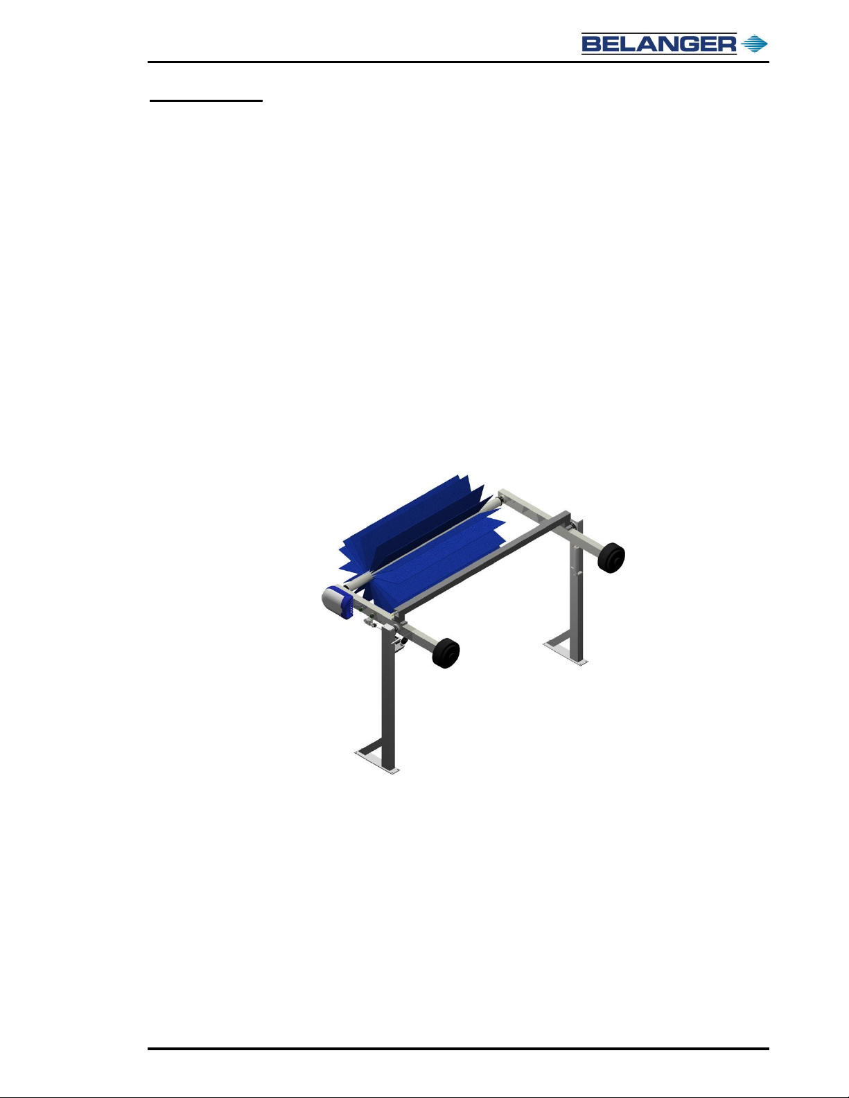
Description of Top Wheel
Congratulations on your purchase of the Belanger, Inc. Top Wheel. The Top Wheel is designed
to operate in only 114” (2.90 m) of tunnel space.
This manual covers Hydraulic and Electric drive units. The purpose of this manual is to
familiarize you with the way that the Top Wheel is installed.
The “Installation” section will be used in conjunction with the location diagram, and the Top
Wheel drawings. All of these combined are your guides to installation.
The “Maintenance” section will be used to make sure you can keep your car wash component
looking and functioning like new.
Whether you have already operated a car wash, or you are new to our industry, you know the
importance of the appearance of a car wash and its equipment to the customer. Keeping the
equipment clean will not only make the equipment easier to maintain, it will act as an example
to your customer to keep their equipment (their vehicle) clean as well. Replacing the cleaning
material in your tunnel as necessary will also help the image of your wash and keep the
customer coming back.
Read through the entire manual to familiarize you with the Top Wheel before installation. When
installation is completed, you will want to keep this manual as a guide to proper maintenance.

TOP WHEELMix and Match
12 Belanger, Inc. * 1001 Doheny Ct. * Northville, MI 48167 * Ph (248) 349-7010 * Fax (248) 380-9681 1MANUL749
Introduction
Before You Get Started
Tools needed for installation:
Forklift
Clamps
Hammer drill with 5/8” (15.9 mm) bit
Tin snips
Torque wrench with 1/2" (12.7 mm) drive
1-1/8” (28.6 mm) socket with 1/2” (12.7 mm) drive
Tape measure (25 foot / 8 m or greater)
Safety glasses
Miscellaneous hand tools
Work gloves
Level
Extension cord
Equipment included: Qty
Driver side leg weldment
1
Passenger side leg weldment
1
Driver side arm assembly
1
Passenger side arm assembly
1
Crossover beam assembly
1
Neo-Tex™or brush wheel
Depending on selection
Neo-Tex™, skins and wash clips
Neo-Tex™ machines ONLY
Accessory box
1
Electric or Hydraulic drive assembly
Depending on selection
Retract assembly option
1 if purchased
Styles Available:
Base top wheel
Standard parts
Wheel option
Neo-Tex™, Whisper Wheel or Brush
Drive Option
Hydraulic or Electric
Retract option
Uses air cylinder and panel to retract
Note: Uncrate and inspect shipment for damage, and to verify that all pieces are there. If there is
any damaged equipment, file a claim with the trucking company immediately. Receiving
party is responsible for filing claim with trucking company. Notify your local distributor or
Belanger, Inc. immediately If shipment is determined damaged or incomplete.
TOP WHEELMix and Match
1MANUL749 Belanger, Inc. * 1001 Doheny Ct. * Northville, MI 48167 * Ph (248) 349-7010 * Fax (248) 380-9681 13
Specifications
Requirements
Physical
Tunnel space required
114” (2.90 m)
Unit height
140” (3.56 m)
Unit width
146” (3.71 m)
Utility
Electrical
3 phase, 1HP / 0.75 kW motor standard
3 phase, 2HP / 1.5 kW motor for Brush Application
110V for Retract Option
Hydraulic
6 GPM @ 900 PSI
Pneumatic
0.3 CFM @ 90 PSI minimum 120 PSI maximum /
0.51 m3/h @ 620kPa minimum 827 kPa maximum
Water
(1) 3/4” hose @ 4 GPM @ 40 PSI / 19.05 mm @ 0.91 m3/h @ 275 kPa
Output
Physical
Vehicle clearance, height
90” (2.29 m)
WARNING –DISCONNECT AND LOCKOUT ELECTRICAL POWER BEFORE
SERVICING ANY EQUIPMENT!
CAUTION –IT IS RECOMMENDED THAT A LICENSED ELECTRICIAN IS
CONTRACTED TO PERFORM ALL ELECTRICAL INSTALLATIONS.
CAUTION –ALWAYS WEAR SAFETY GLASSES WHEN PERFORMING
MAINTENANCE ON ANY EQUIPMENT.
NOTE:
PNEUMATICS MAY NOT BE OPERATED WHEN PART OF insta-KLEEN™
SYSTEM.
CAUTION –A COMPRESSED AIR SYSTEM SHOULD BE SET CORRECTLY TO
SUPPORT 90 PSI NECESSARY TO OPERATE EQUIPMENT BUT SHOULD NEVER
BE SET TO DELIVER MORE THAT 120 PSI AIR PRESSURE TO BELANGER®
SPECIFIED EQUIPMENT. FIELD SUPPLIED PNEUMATIC TUBING MUST HAVE A
MINIMUM OF 2 TIMES THE BURST STRENGTH OF SYSTEM PRESSURE.
NOTE:
YOUR HYDRAULIC SYSTEM MUST BE CAPABLE OF ADJUSTMENT TO 116 RPM
AT 900 PSI (62.1 BAR) WHILE LOADED AGAINST VEHICLE. PLEASE VERIFY
YOUR SYSTEMS CAPABILITY TO MEET THESE SETTINGS WHILE RUNNING A
VEHICLE PRIOR TO INSTALLING PIECE OF EQUIPMENT.
TOP WHEELMix and Match
14 Belanger, Inc. * 1001 Doheny Ct. * Northville, MI 48167 * Ph (248) 349-7010 * Fax (248) 380-9681 1MANUL749
Specifications
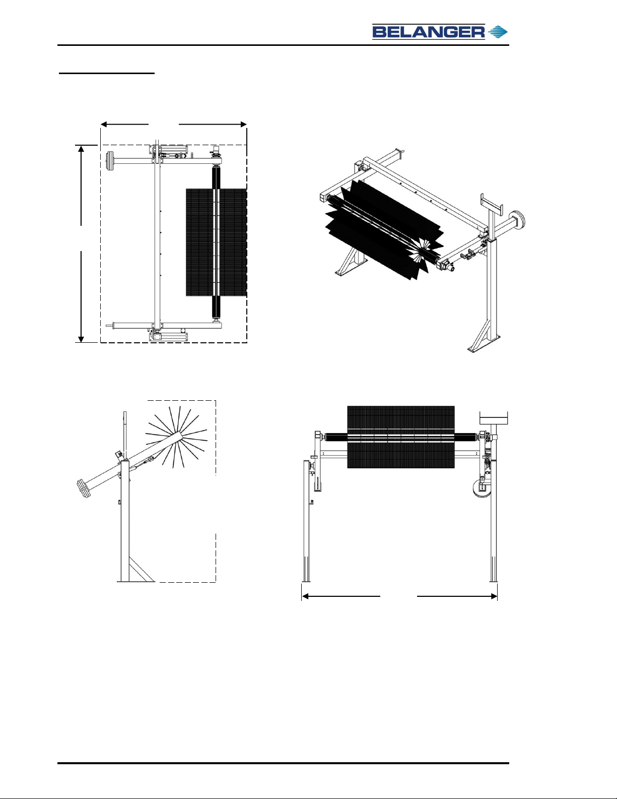
General Dimensions
146”
(3.71 m)
140”
(3.56 m)
146”
(3.71 m)
114”
(2.90 m)
When in
Retract
Position
TOP WHEELMix and Match
1MANUL749 Belanger, Inc. * 1001 Doheny Ct. * Northville, MI 48167 * Ph (248) 349-7010 * Fax (248) 380-9681 15
Installation
Hub Assembly
The type of cleaning material you have ordered will determine the first steps to assembly. Below are
the instructions for the various types. Follow the one that pertains to your system and then move on
to the next section.
Do not discard shipping frame as it will be used to assist in installation of machine.
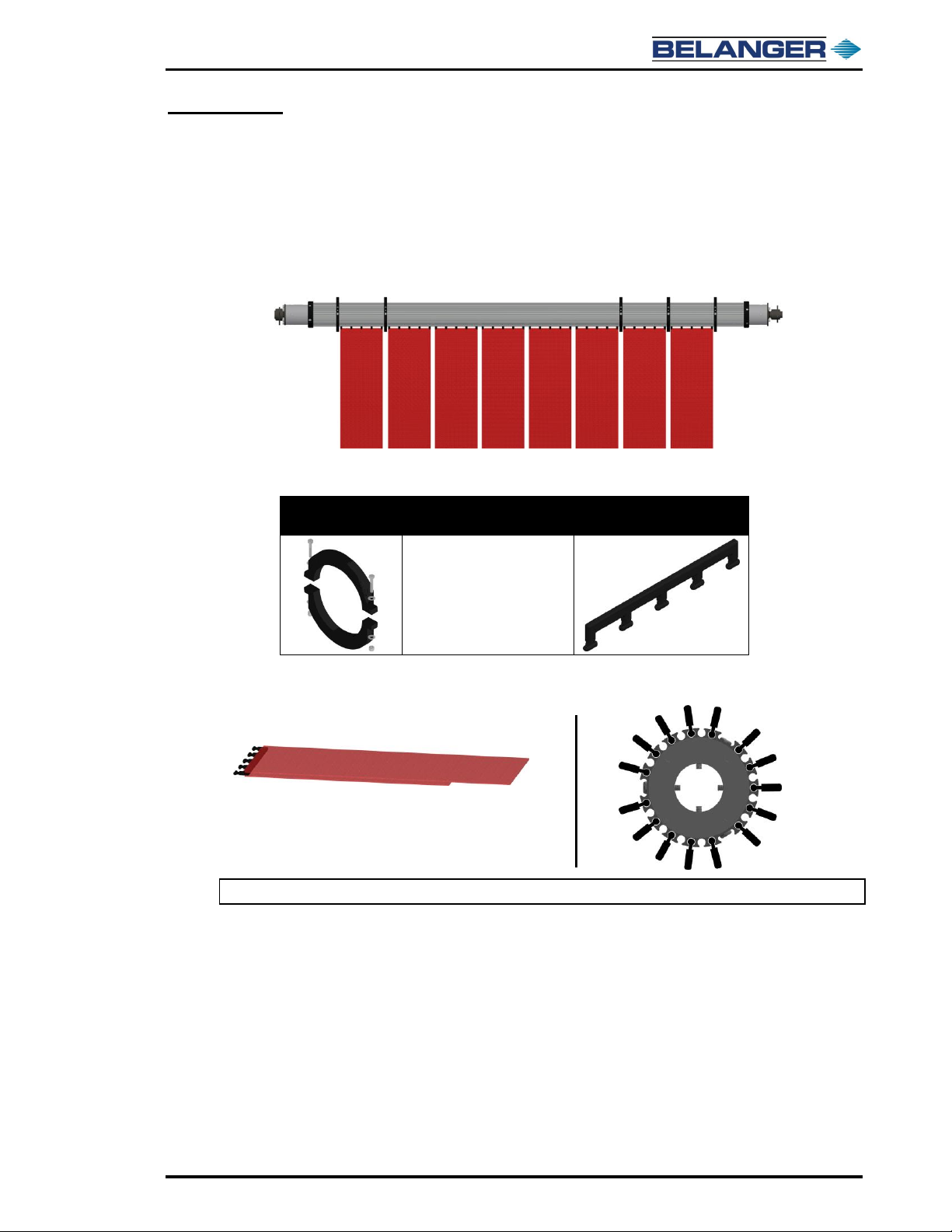
Neo-Tex™ Media Hub Overview
Parts Required
Locking Collar
Clamp Assembly
Clamp Assembly includes
the following:
1PLSTC-CL050
10” (25.4 cm) Wash Clip)
•2 - 1FSTNR-HH081
1/4" - 20 x 1-1/2” bolts
•4 - 1WASHR-FL330
1/4” (6.35 mm) flat washers
•2 - 1NUT-LC201
1/4” (6.35 mm) Nylock™ nuts
The images below show some of the details that are important for proper Neo-Tex™ installation.
Note: Always keep the long side of the Neo-Tex™ on the same side to assist in wheel balance.
Load Neo-Tex
in every other
slot of the hub
•When installed properly, one side of
cleaning material is 6” (15.2 cm)
longer than the other side

TOP WHEELMix and Match
16 Belanger, Inc. * 1001 Doheny Ct. * Northville, MI 48167 * Ph (248) 349-7010 * Fax (248) 380-9681 1MANUL749
Installation
Hub Assembly
Neo-Tex™ Hub Assembly
1) Locate the 2 wooden risers from the shipping pallet and place the hub on the risers with the
5-hole pattern on the driver side and secure the locking collar to the hub as shown below.
2) Slide the first row of 10” (25.4 cm) wide Neo-Tex™ cleaning material into every other slot.
Secure one of the locking collars into place, snug it against the wash clips as shown below.
Note: Slide in the Neo-Tex™ pieces using every other slot on the hub; spin the hub as needed
until there are 15 pieces around the hub.
Passenger
Side
4-Hole
Pattern
13-1/2” (34.3 cm)
This measurement is taken from
the outside of the collar to the
outer edge of the 4-Hole Hub
5-Hole Pattern
Position 1
Driver
Side
Driver Side
Install Row 1
Install Clamp
13-1/2”
(34.3 cm)
Table of contents
Other Belanger Washer manuals


