Belanger SpinLite User manual

SpinLite® Full Side Washer
Belanger, Inc. * P.O. Box 5470 * Northville, MI 48167-5470
Customer Service Phone (248) 349-7010 * Fax (248) 380-9681
SpinLite® Full Side Washer
1MANUAL961 Rev01


Belanger Equipment Owner’s Manual
SpinLite® Full Side Washer
Copyright 2022
Belanger, Inc®
This manual and the accompanying equipment are protected by United States trademark, copyright, and patent laws. You may
make one copy of this manual. Do not make additional copies of this manual or electronically transmit it in any form whatsoever,
in whole or in part, without the prior written permission of Belanger, Inc.®
The registered trademarks used in this document are the property of their respective owners. The use of such trademarks is for
reference purposes only and does not imply sponsorship or approval of Belanger, Inc.® by these companies or any companies
affiliated with their respective owners.


CURRENT REVISION LOG
1MANUL961 Belanger, Inc. * PO BOX 5470 * Northville, MI 48167-5470 * Ph (248) 349-7010 * Fax (248) 380-9681
Rev
Release
Date
Page
Description
01
03/21/22
Front Cover
Updated front cover to new design
Manual
Updated Belanger logo throughout the entire manual
3
Changed Belanger Limited Warranty on Parts from 30 days to 90 days
10
Top image: Removed 47-1/2”
Bottom image: Changed the 47-1/2” dimension to 13” Conveyor: 47-1/2” & 14-1/2” Conveyor: 49”
(per Project #32-523)
13
Added page Installation: Identify Conveyor (per Project #32-523)
14
Added Note about the 13” Conveyor being shown in images in manual
Updated dimension to driver side Full Side Washer 13” Conveyor: 47-1/2” and 14-1/2” Conveyor: 49”
Added to note under image: (13” Conveyor: 47-12” / 14-1/2” Conveyor: 49”) (per Project #32-523)
15
Removed placement dimensions DS: 47-1/2”, PS 103-1/2”, and spacing dimension 78-1/2” for the
staggered QuickFire® Plus assemblies
Updated dimension to driver side Full Side Washer 13” Conveyor: 47-1/2” and 14-1/2” Conveyor: 49”
Added to note under image: (13” Conveyor: 47-12” / 14-1/2” Conveyor: 49”) (per Project #32-523)
16
For Stand-Alone Installation: added dimension for 13” Conveyor: 47-1/2” / 14-1/2” Conveyor: 49”
Added dimension information to Step 2 for the 13” & 14-1/2” wide conveyors (per Project #32-523)
18
Removed placement dimensions DS: 47-1/2”, PS 103-1/2”, and spacing dimension 78-1/2” for the
staggered QuickFire® Plus assemblies
For Staggered with QuickFire® Plus Installation: added dimension for 13” Conveyor: 47-1/2” / 14-1/2”
Conveyor: 49” for placement of driver side SpinLite® Full Side Washer
Added dimension information to Step 2 for the 13” & 14-1/2” wide conveyors ( per Project #32-523)
85 & 86
Changed Motor/Gearbox from 1GEABX-AS660 to 112271 and 1GEABX-AS661 to 112272 (per
Project #10037)
Back Cover
Updated back cover to new design


SpinLite® Full Side Washer
1MANUL961 Belanger, Inc. * PO BOX 5470 * Northville, MI 48167-5470 * Ph (248) 349-7010 * Fax (248) 380-9681 1
Table of Contents
Belanger Incorporated Limited Warranty..............................................................3
Operational Warning...............................................................................................4
Important Safety Information .................................................................................5
Safety Symbols and Signal Words .................................................................................................................................. 5
IMPORTANT Safety Information –MUST READ............................................................................................................ 6
Introduction .............................................................................................................7
Before You Get Started ................................................................................................................................................... 8
Specifications..........................................................................................................9
Requirements .................................................................................................................................................................. 9
Physical .......................................................................................................................................................................................... 9
Utility............................................................................................................................................................................................... 9
Electrical......................................................................................................................................................................................... 9
General Dimensions...................................................................................................................................................... 10
Inspection ..............................................................................................................11
Equipment to Inspect Before Installation....................................................................................................................... 11
Installation .............................................................................................................13
Identify Conveyor .......................................................................................................................................................... 13
Tunnel Placement: Overview ........................................................................................................................................ 14
Standard, Stand-Alone Configuration .......................................................................................................................................... 14
Staggered, with QuickFire® Plus assemblies .............................................................................................................................. 15
Tunnel Placement: Preparation..................................................................................................................................... 16
Tunnel Placement: Stand-Alone Installation ................................................................................................................. 16
Tunnel Placement: Staggered Installation with QuickFire® Plus .................................................................................. 18
Attach the Arm Assemblies ........................................................................................................................................... 20
Install the Drive Shaft Components............................................................................................................................... 24
Connect the Motor/Gearbox and Slip Ring to the Drive Shaft....................................................................................... 27
Connect LED Power Cable to Slip Ring ........................................................................................................................ 31
Install Hub Assemblies, LED Lights with Electrical Connections & ShineMitts™.......................................................... 32
Attach Hub Assemblies to Drive Shafts ....................................................................................................................................... 32
Hub LED Installation and Electrical Connections......................................................................................................................... 35
Load ShineMitts™ on Hub Assemblies........................................................................................................................................ 37
Connect LED Lights to Wire Harness .......................................................................................................................................... 42
Filler Strip Installation for the SpinLite® FSW Assemblies............................................................................................ 44
Utilities........................................................................................................................................................................... 46
Water Connections: Water Line to the SpinLite® Full Side Washers .......................................................................................... 46
Pneumatic Connections: Air Panel to Cylinders........................................................................................................................... 48
Electrical Connections: Air Panel to Controller ............................................................................................................................ 50
Pneumatic Connections: Initial Air Settings for Air Panel ............................................................................................................ 51
Electrical Connections: Main Power to Motors and LED Lights................................................................................................... 52
Electrical Connections: Motor....................................................................................................................................................... 53

SpinLite® Full Side Washer
1MANUL961 Belanger, Inc. * PO BOX 5470 * Northville, MI 48167-5470 * Ph (248) 349-7010 * Fax (248) 380-9681 2
Table of Contents
Maintenance ..........................................................................................................56
Daily ...............................................................................................................................................................................56
Monthly ..........................................................................................................................................................................56
Quarterly ........................................................................................................................................................................56
Troubleshooting .............................................................................................................................................................57
Powder Coating Maintenance ........................................................................................................................................58
Powder Coating Repair..................................................................................................................................................59
Replacing an LED Light on the Hub Assembly ..............................................................................................................61
Motor Gearbox and Torque Plate Replacement ............................................................................................................64
Remove Motor Gearbox & Torque Plate Assembly..................................................................................................................... 64
Prepare New Motor Gearbox & Torque Plate Assembly for Installation...................................................................................... 71
Install New Motor Gearbox & Torque Plate Assembly................................................................................................................. 72
Exploded Parts View......................................................................................................................................................80
Leg Assembly Components: Driver & Passenger Side................................................................................................................ 80
Leg Assembly Components: Water Feed & Manifold Assembly ................................................................................................. 81
Manifold Assembly: 108730 (2) ................................................................................................................................................... 82
Arm Assembly: Overview............................................................................................................................................................. 83
Arm Assembly: Cylinder & Shock Assemblies............................................................................................................................. 83
Arm Assembly: Pivot Shaft & Bumper Assemblies...................................................................................................................... 84
Arm Assembly: Bearing & Electrical Cable Assemblies............................................................................................................... 84
Arm Assembly: Shaft Assembly 110946 (2) ................................................................................................................................ 85
Motor Gearbox & Torque Plate Assembly ................................................................................................................................... 86
Slip Ring Assembly: 110708 (2)................................................................................................................................................... 86
Motor/Gearbox, Drive Shaft & Cover Assembly........................................................................................................................... 87
Hub Assembly 111673: Hub Cover Components ........................................................................................................................ 88
Hub Assembly 111673: Skin and Spider Assembly..................................................................................................................... 89
Hub ShineMitt™ Fill Pattern......................................................................................................................................................... 90
Hub ShineMitt™........................................................................................................................................................................... 90
ShineMitt™ 19” 45 Degree Short Lead: 111060 (Qty. 80)........................................................................................................... 91
ShineMitt™ 22” 45 Degree Short Lead: 111053 (Qty. 64)........................................................................................................... 92
ShineMitt™ 25” 45 Degree Short Lead: 111369 (Qty. 32)........................................................................................................... 93
Hub Assembly: LED RGB Assembly 111674 .............................................................................................................................. 94
LED RGB Assembly: 111674 (2) ................................................................................................................................................. 94
Filler Strips: Driver Side Arm & Leg Assembly............................................................................................................................. 95
Filler Strips for Passenger Side Arm & Leg Assembly................................................................................................................. 96
Air Panel: 102060 Assembled View............................................................................................................................................. 97
Air Panel: 102060 Exploded View................................................................................................................................................ 97

SpinLite® Full Side Washer
1MANUL961 Belanger, Inc. * PO BOX 5470 * Northville, MI 48167-5470 * Ph (248) 349-7010 * Fax (248) 380-9681 3
Belanger Incorporated Limited Warranty
LIMITED WARRANTY:
Equipment:
Subject to the limitations stated below, Seller warrants that the Equipment sold hereunder, which is fabricated by Seller, shall
be free from defects in workmanship and material under normal use and service for a year plus 30 days from the date of
invoice - CATPumps will be warranted for 2 years from the date of invoice.
Parts:
Subject to the limitations stated below, Seller warrants that the Parts sold hereunder, shall be free from defects in
workmanship and material under normal use and service for 90 days from the date of invoice.
Limitations on All Warranties:
The warranties contained in this Section 13 are subject to the following limitations: (1) they are void if the factory specifications
for operation and maintenance, found in original equipment manuals, and component manuals, are not followed, or if other
than factory authorized erection, alterations or modifications are made to any Parts or Equipment; (2) defective Parts are
warranted to the Purchaser only for repair or replacement through an authorized Purchaser or Distributor of Seller, or direct
with Seller for a period of 13 months from the date of invoice; however, this warranty excludes all claims for failure resulting
from normal wear and tear, improper installation, omission of factory specified preventative maintenance, misuse, abuse,
negligence, third party damages, or acts of God and Purchaser agrees to submit to and assist Seller or its authorized
Purchaser or Distributor in conducting in-warranty inspections of the Goods including inspection of any Equipment or Parts
claimed to be defective by the Purchaser; (3) the cost of providing labor or repair to replace Equipment and Parts warranted
to Purchaser will be included within the warranty only if such claim is made within 120 days from the date of invoice and then
only during normal business hours through an authorized Purchaser or Distributor of Seller, or direct with Seller, and labor
and service provided beyond the labor warranty period shall be subject to labor charges at the rates established by the local
authorized Purchaser or Distributor or direct with Seller; (4) the warranties shall be void for all Equipment failures and
premature Part wear caused by the use of corrosive chemicals in the wash process, and the following list includes some, but
not all, of the particularly corrosive chemicals that if used in conjunction with Equipment or Parts will void the warranty:
Hydrofluoric Acid, Ammonium Bi-fluoride, Bromic Acid, Muriatic Acid, Sulfonic Acid, Phosphoric Acid, Hydrogen Cyanide,
Hydrochloric Acid, Sodium Hydroxide and Chlorinated Solvents; (5) Seller makes no warranty, express or implied, with
respect to the design or operation of any entire system, in which Seller’s Equipment or Parts sold hereunder are mere
components;(6) in no event shall Seller be liable for any incidental, special, consequential, punitive or exemplary damages
resulting from the furnishing, performance or use of any Goods or services sold pursuant hereto, whether due to a breach of
contract, breach of warranty, negligence or any other claim at law or equity. Seller shall not be liable for any damages of any
kind, including, but not limited to, loss of business; inconvenience, or property damage of any kind; nor for any damages of
whatever nature resulting in any way from the Purchaser’s selection and use of any chemicals not manufactured exclusively
by Seller but used with the purchased Equipment or Parts; or for any service not expressly provided herein related to or
arising from the Equipment or Parts sold. Seller shall not be liable for damages resulting from Purchaser’s use of any
engineering recommendations, sales representations, technical assistance, advice, or data other than that information
contained in Belanger manuals; (7) all warranties, express, implied, or statutory, pertaining to the Equipment and Parts apply
to the Purchaser only; are not transferable; are fully set forth herein; and no addition to or modification thereto shall be
binding upon the Seller, unless made in writing and signed by a duly authorized employee of Seller.
No Other Warranties:
THIS LIMITED WARRANTY FOR EQUIPMENT AND PARTS IS EXPRESSLY IN LIEU OF ALL OTHER
WARRANTIES, EXPRESS OR IMPLIED, WHETHER STATUTORY OR OTHERWISE, INCLUDING ANY
IMPLIED WARRANTY OF MERCHANTABILITY OR WARRANTY OF FITNESS FOR A PARTICULAR
PURPOSE. THE IMPLIED WARRANTIES OF MERCHANTABILITY AND FITNESS FOR A PARTICULAR
PURPOSE CONTAINED IN THE UNIFORM COMMERCIAL CODE –SALES ARE EXPRESSLY DISCLAIMED.
Copyright ©2020 by Belanger, Inc. All rights reserved. No part of this work may be reproduced or transmitted in any form or
by any means, electronic or mechanical, including photocopying and recording, or by any information storage or retrieval
system, except as may be expressly permitted by the 1976 Copyright Act. Belanger reserves the right to change or modify
the Belanger Inc. Limited warranty without notice.

SpinLite® Full Side Washer
1MANUL961 Belanger, Inc. * PO BOX 5470 * Northville, MI 48167-5470 * Ph (248) 349-7010 * Fax (248) 380-9681 4
Operational Warning
Formulations containing the chemicals listed below are particularly dangerous and should not be
used even at low concentrations:
•Hydrofluoric Acid
•Ammonium Bi-fluoride
•Bromic Acid
•Muriatic Acid
•Sulfonic Acid
•Phosphoric Acid
•Hydrogen Cyanide
•Hydrochloric Acid
•Chlorinated Solvents
Belanger, Inc.®, does not endorse or condone the use of chemicals that are potentially dangerous to human health, the
environment, or property. Belanger® recognizes that it is the right and sole decision of the end-user operators of our
equipment as to the type and dilution ratio of the chemicals used in their facilities. We strongly recommend that the end-
user does not select products containing any of the chemicals listed above as an ingredient in the wash solutions. The
chemicals listed above are potentially dangerous to human health and have a detrimental, deteriorating effect on the
equipment and the facility. Be advised that a portion of, or all of your warranty will be voided if you determine to use any of
the chemicals listed above as an ingredient in the wash solutions in conjunction with your Belanger® automatic car wash
equipment:
Limitation (4), of Paragraph (8), Limited Warranty, of the Belanger® Terms and Conditions of Sales describes the
potential limitation of warranty due to your chemical selection:
(4) This warranty shall be void for all equipment failures and premature component wear caused by the use of corrosive
chemicals in the wash process. The following list includes some, but not all, of the particularly corrosive chemicals that
if used in conjunction with Belanger® equipment will void the warranty: Hydrofluoric Acid, Ammonium Bi-fluoride,
Bromic Acid, Muriatic Acid, Sulfonic Acid, Phosphoric Acid, Hydrogen Cyanide, Hydrochloric Acid, and Chlorinated
Solvents. The Purchaser also agrees to accept the responsibility and liability for the selection and use of any chemicals
listed above;
However, should the end-user decide to use formulations containing any of the above ingredients, the end-user should
institute a comprehensive training program and implement detailed operational parameters within their organization for the
proper handling and treatment of such products to minimize the potential dangers involved. Consult your chemical supplier
for assistance in establishing operational guidelines in the use of their products. MSDS (Material Safety Data Sheet) should
be obtained from the chemical supplier before using any chemical formulation.
The installer is responsible for re-tightening ALL lugs, set screws, and terminals
located in the electrical panels during the installation process. Components may
vibrate loose during shipping.
CAUTION

SpinLite® Full Side Washer
1MANUL961 Belanger, Inc. * PO BOX 5470 * Northville, MI 48167-5470 * Ph (248) 349-7010 * Fax (248) 380-9681 5
Important Safety Information
This section introduces the hazard and safety precautions associated with installing, maintaining, or
servicing this product. Before performing any task on this product, read this safety information and the
applicable sections in this manual, where additional hazards and safety precautions for your task may be
found. Electrical shock could occur and cause death or serious injury if these safe service procedures are
not followed.
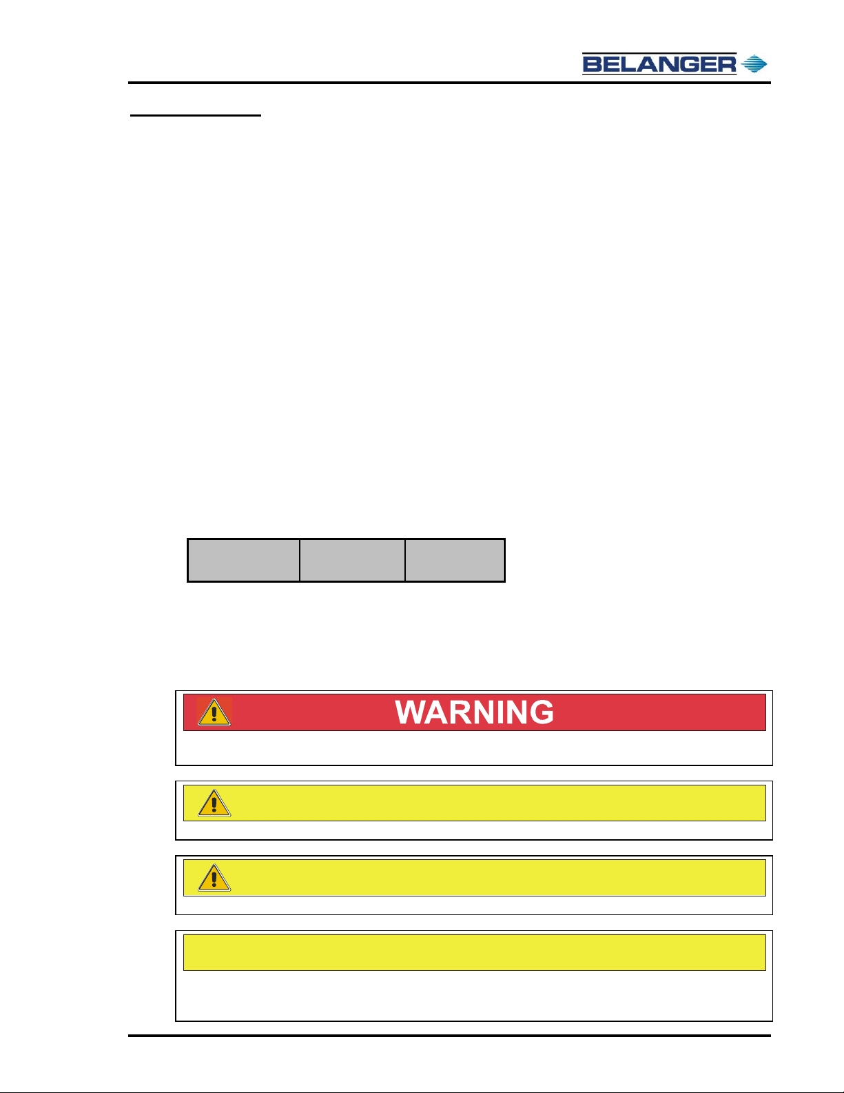
Safety Symbols and Signal Words
Alert Symbol
This safety alert symbol is used in this manual and on warning labels to alert you to
precautions, which must be followed to prevent potential personal safety hazards.
Obey safety directives that follow this symbol to avoid possible injury or death.
Signal Words
The signal words used in this manual and on warning labels tell you the seriousness of particular
safety hazards. The precautions that follow must be followed to prevent death, injury, or damage to
the equipment.
DANGER
This signal word is used to alert you to a hazard or unsafe practice which WILL RESULT IN
DEATH OR SERIOUS INJURY
This alerts you to a hazard or unsafe practice which COULD RESULT IN DEATH OR SERIOUS
INJURY
CAUTION
This signal word designates a hazard or unsafe practice which MAY RESULT IN MINOR INJURY
CAUTION
When used by itself, CAUTION designates a hazard or unsafe practice which MAY RESULT IN
PROPERTY OR EQUIPMENT DAMAGE
Before You Begin
Only trained or authorized individuals knowledgeable in the related procedures should install, inspect,
maintain or service this equipment.
Read the Manual
Read, understand and follow this manual and any other labels or related materials supplied with this
equipment. If you do not understand the procedure, call a Belanger, Inc. representative at 248-349-
7010. It is imperative to your safety and the safety of others to understand the procedures before
beginning work.

SpinLite® Full Side Washer
1MANUL961 Belanger, Inc. * PO BOX 5470 * Northville, MI 48167-5470 * Ph (248) 349-7010 * Fax (248) 380-9681 6
Important Safety Information
IMPORTANT Safety Information –MUST READ
Safety Warnings
DANGER
DISCONNECT MAIN POWER SUPPLY PRIOR TO
SERVICING OR MAINTAINING EQUIPMENT
Belanger recommends that all workers observe the OSHA (U.S. Department of Labor
Occupational Safety & Health Administration) Lockout / Tagout procedure prior to
performing service or maintenance on machinery and equipment. Doing so will
prevent unexpected energization, startup, or release of hazardous energy while
maintenance and servicing activities are being performed.
BE SURE TO OBSERVE THE OPERATING ENVELOPE.
EQUIPMENT MAY START UNEXPECTICALLY. OVERHEAD,
ROTATING, AND/OR MOVING COMPONENTS COULD RESULT
IN SERIOUS INJURY OR DEATH.
BE AWARE OF FOREIGN OBJECTS IN THE AREA
SURROUNDING A ROTATING PIECE OF EQUIPMENT.
OBJECTS MAY BECOME TANGLED WITH EQUIPMENT AND
COULD RESULT IN SERIOUS INJURY OR DEATH.
CAUTION
BE AWARE OF HAZARDS ASSOCIATED WITH
EQUIPMENT INSTALLED ON THE FLOOR
THAT MAY BE A TRIP HAZARD.
It is imperative to your safety and the safety of others to always follow safe work
procedures.

SpinLite® Full Side Washer
1MANUL961 Belanger, Inc. * PO BOX 5470 * Northville, MI 48167-5470 * Ph (248) 349-7010 * Fax (248) 380-9681 7
Introduction
Thank you for your purchase of the Belanger, Inc. SpinLite® Full Side Washers. This manual will familiarize
you with the SpinLite® Full Side Washer installation, operation, and maintenance.
Both the driver and passenger side SpinLite® Full Side Washers are easily assembled and mounted to
the tunnel floor. Once the equipment is assembled and in place, the ShineMitt™ cleaning material and
utility hook-ups can be performed to complete the installation of the SpinLite® Full Side Washers.
Please read the entire instruction manual before attempting to install the equipment and refer to it
throughout the installation process. Keep this manual as a guide to proper maintenance.
IT IS IMPERATIVE THAT WHEELS ARE SPINNING DURING
ANY PERIOD THAT THE CONVEYOR IS ACTIVATED
SpinLite® Full Side Washer
Driver Side Assembly
SpinLite® Full Side Washer
Passenger Side Assembly
Motor/Gearbox
& Cover
Hub Assembly
with LED Lights
ShineMitt™
Cleaning Material
Water
Manifold
Pivot Stop
Leg
Assembly
Arm Asy. with Drive
Shaft & Bearings
Hub Cover
Electrical
Junction Box

SpinLite® Full Side Washer
1MANUL961 Belanger, Inc. * PO BOX 5470 * Northville, MI 48167-5470 * Ph (248) 349-7010 * Fax (248) 380-9681 8
Introduction
Before You Get Started
Below is a list of the SpinLite® Full Side Washer equipment you will receive in your shipment and the tools
that are needed to install the equipment.
Tools needed for installation:
Forklift (optional)
Level
Hammer drill with 5/8” bit
50-foot extension cord
Tape measure (25 feet or greater)
Safety glasses
Miscellaneous hand tools
Work gloves
Equipment included: Qty
SpinLite® FSW Driver Side Leg Assembly
1
SpinLite® FSW Passenger Side Leg Assembly
1
SpinLite® FSW Driver Side Arm Assembly
1
SpinLite® FSW Driver Side Arm Assembly
1
SpinLite® FSW Drive Shaft Assembly: 110946
2
SpinLite® FSW Drive Hub Assembly: 111673
2
ShineMitt™ 19” Cleaning Material: 111060
80
ShineMitt™ 22” Cleaning Material: 111053
64
ShineMitt™25” Cleaning Material: 111369
32
Motovario Motor/Gearbox STD V: 110935 or 575V: 110967
2
Motor/Gearbox Cover Assembly: 110720
2
SpinLite® FSW LED Light Set: 111674
2
SpinLite® Slip Ring Assembly: 110708
2
SpinLite® FSW Filler Strip: 110746
2
Accessory Box: 108958
1
Accessory Box (108958) includes: Qty
Air Panel Assembly: 102060
1
Kwik Bolts 3 Zinc 5/8” x 6”: 1FSTNR-ST750
12
Clamp Single Ear for 1/2” Hose: 1CLAMP467
4
Keystock 8 x 7 x 100mm: 1STEEL-KY150
2
Collar Lock 2pc Split 1-3/8 x 1/2" wide: 1COLLAR333
2
Arm Pivot Washer: 7202
2
Stainless Steel Flat Washer 9/16”: 1WASHR-FL747
4
Cotter Pin Zinc 1/8 x 1”: 1RETNR129
4
Fasteners HHCS 5/16 –18 x ¾” ARMOR COAT: 1FSTNR-HH162
4
Lock Washer 5/16” SS: 1WASHR-LC270
4
Note: Uncrate and inspect the shipment for damage, and verify that all pieces are there. If there is any
damaged equipment, file a claim with the trucking company immediately. Receiving party is
responsible for filing a claim with the trucking company. Notify your local distributor or
Belanger, Inc.® immediately if the shipment is determined damaged or incomplete.
SpinLite® Full Side Washer
1MANUL961 Belanger, Inc. * PO BOX 5470 * Northville, MI 48167-5470 * Ph (248) 349-7010 * Fax (248) 380-9681 9
Specifications
Requirements
Physical
Tunnel space: required driver side
95-5/8”
Tunnel space: required passenger side
95-5/8”
Utility
Electrical
Two 1 HP, 3-Phase Motors, terminated in Junction Box at the top of the Leg. See the chart
below for requirements.
Two 24V Signal Wires from the configured LED SpinLite Lighting Panel, terminated at the
Junction Box at the top of each Leg Assembly
One 110V Control Wire terminated at Supplied Pneumatic Control Panel
Water
One 1/2” poly-flow tube for Chemical/Water, Tee’d to feed driver and passenger side SpinLite®
Full Side Winder assemblies, terminated at Water Manifold on each Leg Assembly
Water Output: 6 GPM total (Two Nozzles per side: 1.5 GPM x 65°@ 40 psi per Nozzle)
Pneumatic
One 1/4” poly-flow tube Main Pneumatic feed to Air Panel (1CFM)
Four 1/4” Airlines for Extend and Retract of the Arm Cylinders on each SpinLite® Full Side
Washer® Assembly
Electrical
Voltage
Hz
FLA
Per Motor
208
60
4.6
230
60
4.2
480
60
2.1
575
60
1.7
DISCONNECT AND LOCKOUT ELECTRICAL POWER BEFORE SERVICING ANY
EQUIPMENT!
CAUTION
Always wear safety glasses when performing maintenance on any equipment.
CAUTION
It is recommended that a licensed electrician is contracted to perform all electrical installations.
CAUTION
A compressed Air System should be set correctly to support 90 PSI necessary to operate equipment,
but should never be set to deliver more than 120 PSI air pressure to the Belanger specified
equipment.
SpinLite® Full Side Washer
1MANUL961 Belanger, Inc. * PO BOX 5470 * Northville, MI 48167-5470 * Ph (248) 349-7010 * Fax (248) 380-9681 10
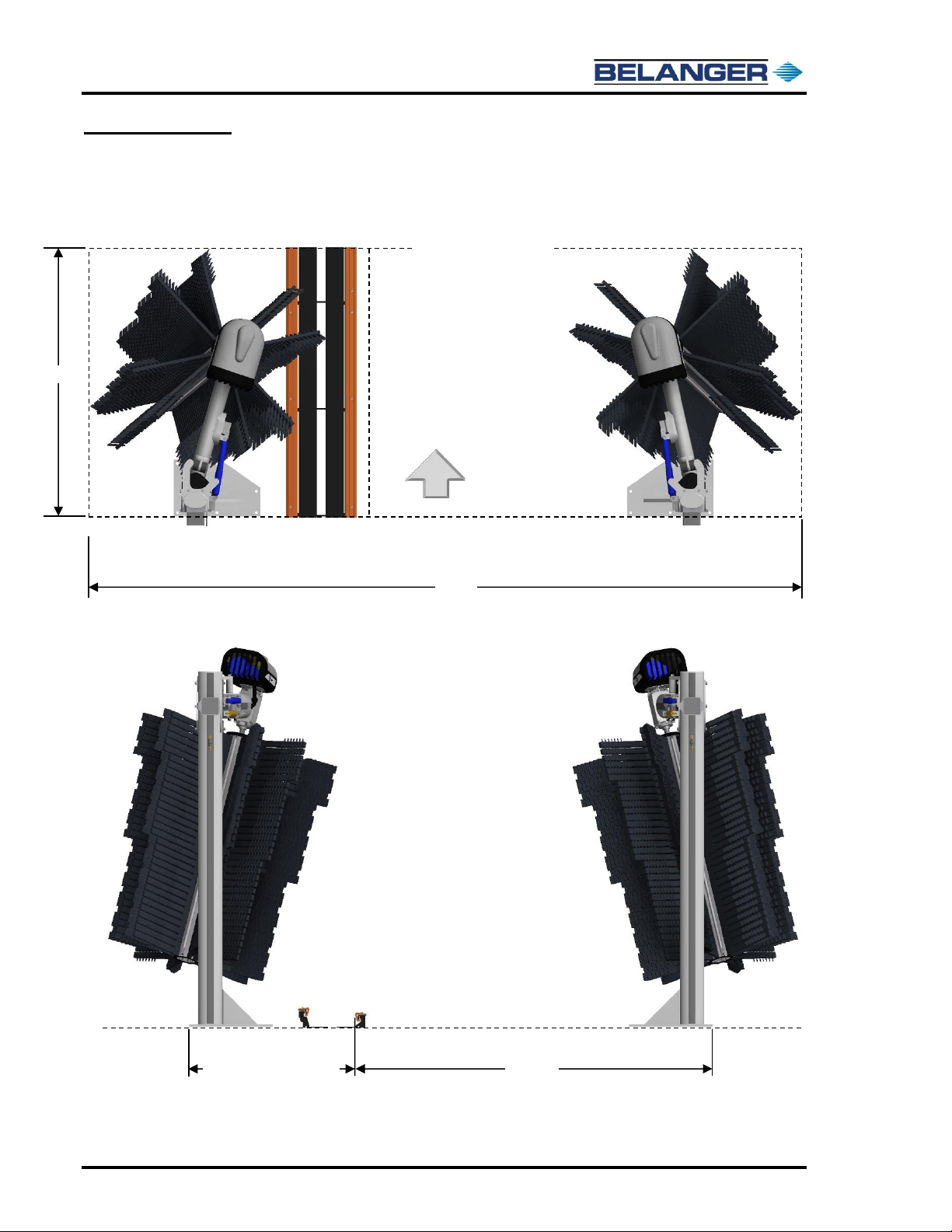
Specifications
General Dimensions
Top View
107”
Equipment Envelope
187”
Entrance View
Floor
13” Conveyor: 47-1/2”
14-1/2” Conveyor: 49”
102-1/2”
SpinLite® Full Side Washer
1MANUL961 Belanger, Inc. * PO BOX 5470 * Northville, MI 48167-5470 * Ph (248) 349-7010 * Fax (248) 380-9681 11
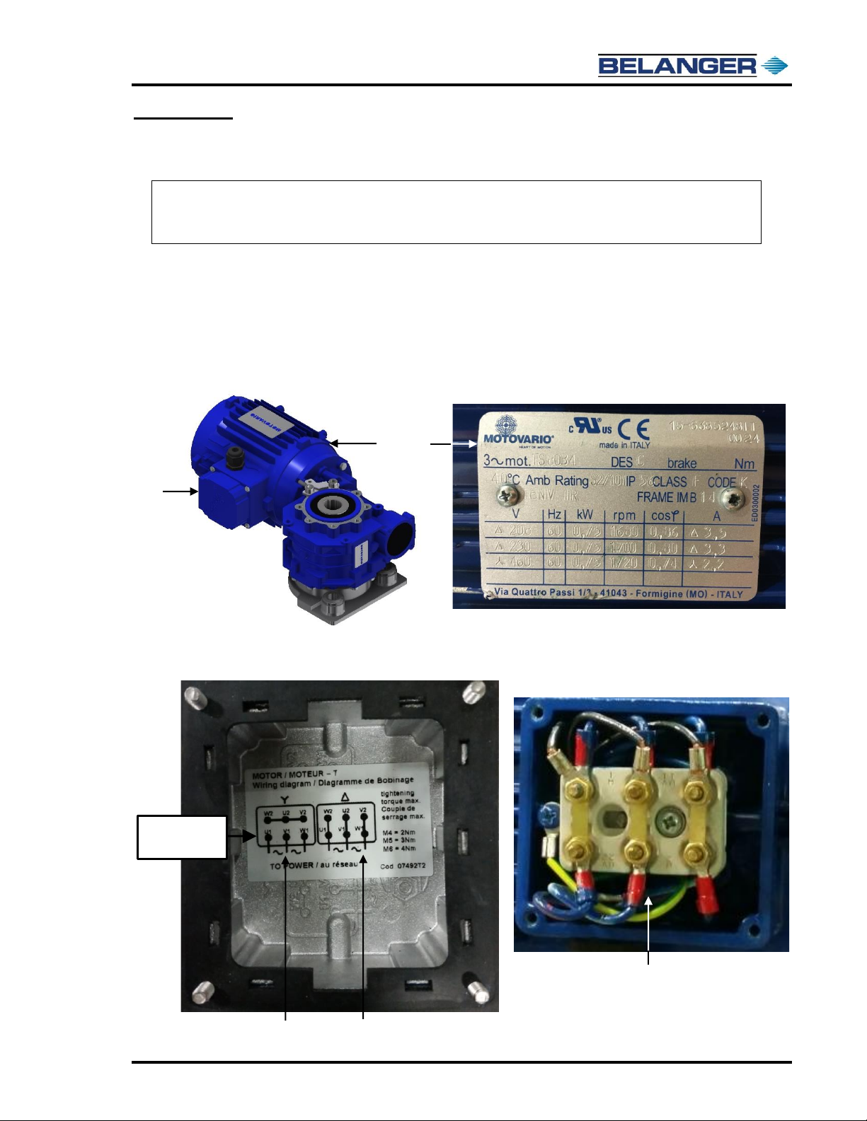
Inspection
Equipment to Inspect Before Installation
Uncrate the SpinLite® Full Side Washer components and inspect for damage.
The SpinLite® FSW assemblies each have a 1HP 3-Phase motor that comes wired for the voltage selected
when ordered which was either 208/230, 460, or 575 VAC.
Before removing the SpinLite® Full Side Washer components from the shipping pallets do the following:
verify that the motors have been wired to the correct voltage for the site and confirm that each of the Arm
Assemblies has a pre-routed LED Cable and Motor Cable.
1) Locate the two (2) Motor/Gearbox assemblies. Refer to the Motor Tag on the Motor to determine
the proper wiring for the site voltage.
2) Remove the Motor Cover to expose the Motor Wires, refer to the Wire Diagrams on the inside of
the Motor Cover to verify that the motor is wired properly.
Note: If there is any damaged equipment, file a claim with the trucking company immediately.
Receiving party is responsible for filing claim with trucking company. Notify your local
distributor or Belanger, Inc. immediately if shipment is determined damaged or incomplete.
Motor
Cover
Showing Delta ∆
Motor Wiring for
208/230 VAC
Delta ∆is used for sites with
208/230 VAC
“Y” is used for sites with
460 VAC
Motor Wiring
Diagrams
Motor Tag

SpinLite® Full Side Washer
1MANUL961 Belanger, Inc. * PO BOX 5470 * Northville, MI 48167-5470 * Ph (248) 349-7010 * Fax (248) 380-9681 12
Inspection
Equipment to Inspect Before Installation
1) The Motor & LED Electrical Cables have been pre-routed through the Arm Assemblies and
the ends are extending out through the conduit fittings.
CAUTION
It is recommended that a licensed electrician is contracted to perform all electrical installations.
2) The Motor Cable and LED Cable, on the Pivot end of the Arm, will be connected to their
corresponding Main Power Supply Line in the Electrical Enclosure on the Leg Assembly. The
other end of the Motor Cable will be connected to the Motor. These electrical connections will
be explained in the Utilities Section of this manual and should be performed by a licensed
electrician.
3) The other end of the LED Cable has a quick connector and will be connected to the Slip Ring
Wire inside the Motor/Gearbox Cover during the Installation of the SpinLite® FSW
Assemblies.
During Installation:
This end of the cables will
be routed to the Electrical
Junction Box on the Leg
Assemblies.
Conduit Fitting
Motor Cable
LED Cable
LED Cable
Arm Assembly
3/8” LiquidTite Conduit,
in two (2) places,
encloses each Cable
3/4” LiquidTite Conduit
encloses both Cables
Motor Cable
During Installation:
This end of the Motor & LED Cables will be
routed into Motor/Gearbox Cover and the
LED Cable will be connected to the Slip Ring.
Then when the utilities are connected the
Motor Cable will be wired to the Motor by a
licensed electrician.
Other manuals for SpinLite
1
Table of contents
Other Belanger Washer manuals


Popular Washer manuals by other brands


Beko
Beko WMB 81443 LX quick start guide

Samsung
Samsung WW11R64 Series user manual

Frigidaire
Frigidaire FFTW1001PW0 use & care

Electrolux
Electrolux LAVAMAT 61271 BI user manual

Harbor Freight Tools
Harbor Freight Tools CENTRAL MACHINERY 91966 Assembly and operating instructions

LG
LG SIGNATURE WTS02TLWHN owner's manual