Belden Grass Valley DXF-4K User manual

Installation Guide
M3033-6203-AA
2018-04-30
DXF-4K
Optical AV Media Extender

ii
Notices
Copyright and Trademark Notice
Copyright © 2018–2016, Grass Valley Canada. All rights reserved.
Belden, Belden Sending All The Right Signals, and the Belden logo are trademarks or
registered trademarks of Belden Inc. or its affiliated companies in the United States and
other jurisdictions. Grass Valley, DXF-4K, Kaleido, Grass Valley are trademarks or registered
trademarks of Belden Inc., and other parties may also have trademark rights in other terms
used herein.
Terms and Conditions
Please read the following terms and conditions carefully. By using this documentation, you
agree to the following terms and conditions.
Grass Valley hereby grants permission and license to owners of DXF-4Ks to use their
product manuals for their own internal business use. Manuals for Grass Valley products may
not be reproduced or transmitted in any form or by any means, electronic or mechanical,
including photocopying and recording, for any purpose unless specifically authorized in
writing by Grass Valley.
A Grass Valley manual may have been revised to reflect changes made to the product
during its manufacturing life. Thus, different versions of a manual may exist for any given
product. Care should be taken to ensure that one obtains the proper manual version for a
specific product serial number.
Information in this document is subject to change without notice and does not represent a
commitment on the part of Grass Valley.
Warranty information is available from the Legal Terms and Conditions section of Grass
Valley’s website (www.grassvalley.com).
Recycling
Visit www.grassvalley.com for recycling information.
Title DXF-4K Installation Guide
Part Number M3033-6203-AA
Revision 2018-04-30, 14:55

1
DXF-4K Installation Guide
Overview
The DXF-4K optical extension kit transmits HDMI video resolutions up to Ultra High
Definition 4K video with HDR support to extend the reach of a limited-distance signal
medium (HDMI cable) to a much farther distance by using fiber optic cable. For this, it uses
a customer supplied OM41multimode fiber (MMF) to extend signal transmission to up to
1000m without any loss of signal integrity. This extension kit consists of a transmitter
module and a receiver module, power supplies, HDMI cables, and HDMI cable lock clips.
The DXF-4K-DVI kit includes a DVI to HDMI adapter for use with multiviewer models that
have a DVI mosaic output.
This installation manual describes how to install and use the DXF-4K optical extension kit.
Model Description
The following DXF-4K extension kit models are available.
See Unpacking, on page 3 for the kit contents.
Application
The supported application is to extend a Grass Valley video equipment’s HDMI output to a
display with an HDMI input by directly connecting the transmitter to the video source and
by connecting the receiver directly to the display. Both the transmitter and receiver must be
powered by an external power source such as an unused USB port or by a supplied wall
plug power supply.
1.NOTE: OM1, OM2, and OM3 fiber types are not supported.
Model Description
DXF-4K Optical HDMI - HDMI 4K Extension system
DXF-4K-DVI Optical DVI - HDMI 4K Extension system

2
DXF-4K Installation Guide
Using the DXF-4K with non-HDMI Multiviewer Outputs
The following figure shows the typical connections for DXF-4K kit.
Fig. 1-1: Typical DXF-4K kit application
Using the DXF-4K with non-HDMI Multiviewer Outputs
Certain Grass Valley multiviewers do not have HDMI mosaic outputs. However, the DXF-4K
optical extension system may still be used with the multiviewer by using a supported
adapter supplied by Grass Valley.
Supported Adapters
The following adapters have been tested with this solution.
• Display Port to HDMI adapter (sold with Kaleido-IP multiviewers)
• Quad link SDI to HDMI 2.0 converter (sold with 4K multiviewers)
• DVI to HDMI adapter, for use with a KXO-DUAL card, for example (sold as part of the
DXF-4K-DVI Kit)
The following figure shows the typical connections for DXF-4K-DVI kit or when a DXF-4K kit
is used with a supported adapter.
Fig. 1-2: Using a DXF-4K with a supported adapter
DXF-4K Transmitter
To Source’s Mosaic Output
DXF-4K Receiver
Display
To Display’s
HDMI Input
AC
Outlet
Typical HDMI Video Source
Multimode Fiber
AC Outlet
DXF-4K Receiver
DXF-4K Transmitter
To Source’s Mosaic Output
Display
To Display’s
HDMI Input
AC
Outlet
Typical DVI / Display Port / SDI Video
Source Multimode Fiber
AC Outlet
Supported Adapters

3
DXF-4K
Installation Guide
Unsupported Applications
Using this kit with the following equipment has not been tested:
• Use with any non-Grass Valley video adapter such as a USB to HDMI adapter
• Use with HDMI extension cables
• Use with USB cables other than the ones supplied in this kit
• Use with power supply adapters other than the ones supplied in this kit
• Use with a DVI to HDMI adapter other than the one supplied in the DXF-4K-DVI kit
Unpacking
Unpack the DXF-4K / DXF-4K-DVI kit. The kit should contain the following items. If anything
is missing, contact your distributor or Grass Valley (see Grass Valley Technical Support, on
page 12). Items that are shown below with a part number are available as Field Replacement
Units (FRUs) for maintenance purposes.
Supplied
Quantity Description (FRU part number)
Supplied with this
Optical Extension Kit
DXF-4K DXF-4K-DVI
1DXF-4K transmitter (DXF-4K-TX)
1DXF-4K receiver (DXF-4K-RX)
2Wall plug universal AC power supply to female USB A
Each power supply includes four plug adapters for UK, US,
AU, and EU (PSU-AC-USB)
2USB cable, male USB A to male micro-USB B (CBL-USB-A-
MICRO-6)
2HDMI cable lock clip
1Male DVI to female HDMI adapter (ADAPTER-DVI-HDMI)

4
DXF-4K Installation Guide
Optical Extender Overview
The physical dimensions of the DXF-4K are the same for both the transmitter and the
receiver. The following diagram shows the DXF-4K’s physical dimensions, the electrical
connections, and the location of the status indicator.
Fig. 1-3: DXF-4K Overview
The included wall plug universal power supply is supplied with four plug adapters for UK,
US, AU, and EU.
Fig. 1-4: Universal Power Supply
14.3 [362]
inches [millimeters]
3.47 [88.2]
Transmitter HDMI Type A Input
0.45
[11.5]
1.19
[30.3]
Optical
Output
Power
Input
Status Indicator
Receiver HDMI Type A Output
Optical
Input
Power
Input
Status Indicator
SOURCE DISPLAY
CAUTION
Risk of electrocution: Always attach the plug adapter to the universal power
supply first, before connecting the plug adapter to an electrical socket.

5
DXF-4K
Installation Guide
Status Indicator Interpretation
Both the transmitter and receiver have a status indicator.
Fiber Optic Handling
Never assume a fiber is dark. Never look directly into the end of a fiber cable. All employees
in the area must wear laser safety glasses with side shields.
Installing connectors on a fiber requires special handling procedures. Read and follow the
fiber and connector manufacturer’s instructions.
Protect fiber cable ends and optical ports on equipment from dust and dirt.
• When a fiber cable is disconnected, fit a protective cap on the end.
• When no fiber cable is connected to an optical port, insert a protective cap.
Store unused protective caps in an airtight container to prevent the transfer of dust to the
fiber connectors when used in the future.
Installation
Use field-supplied OM4 Multimode Fiber (MMF) single fiber optical cable fitted with SC
connectors with this kit. For an installation overview, see Application, on page 1. Proceed as
follows:
1 Connect the optical cable to the DXF-4K receiver (RX6F-SH51-03A-BK): first remove the
protective cap from the receiver’s optical input port and then insert the optical cable
connector into the receiver’s optical input port.
Status Indicator Color Interpretation
Off Module has no power.
Red – Steady/Flashing Module has detected an open fiber connection and has disabled
the lasers for user protection.
Yellow Fiber detected but link initialization failed. See Troubleshooting, on
page 8.
Green – Flashing Link functional with no HDCP video.
Green – Steady Link functional with HDCP 1.x video.
Blue Link functional with HDCP 2.x video.
Pink/Purple –
Steady/Flashing
Fiber connection is open and lasers have been disabled. Boot
loader is connected.
Optical Cable
Protective Cap

6
DXF-4K Installation Guide
Installation
2 Attach the HDMI cable lock sleeve to the receiver’s HDMI output cable.
3 Using an available surface screw, attach the HDMI cable lock strap to the display (for
example, the HDMI cable lock sleeve can be located anywhere along the HDMI cable’s
length and a VESA mount screw can be used to attach the HDMI cable lock strap to the
display).
4 Insert the HDMI cable lock strap into the HDMI cable lock sleeve and connect the
DXF-4K receiver output plug to the Display’s HDMI Input jack.
5Connectthemicro-USB B plug of the USB cable to the DXF-4K receiver’s power input
jack.
6 Power the DXF-4K receiver: connect the other end of the USB cable to a USB power
source such as an unused USB jack on the display or to the supplied power supply. If
used, plug-in the power supply to an outlet (mains).
7 Use a field-supplied tie-wrap to bundle up excess cable lengths. Do not fully tighten
the tie-wrap in order to not damage the optical cable by crushing or kinking the cable.
8 Connect the optical cable to the DXF-4K transmitter (TX6F-SH51-03A-BJK): first remove
the protective cap from the transmitter’s optical output port and then insert the optical
cable connector into the transmitter’s optical output port.
USB Cable

7
DXF-4K
Installation Guide
9 Attach the HDMI cable lock sleeve to the transmitter’s HDMI input cable.
10 Using an available surface screw, attach the HDMI cable lock strap to the display (for
example, use the screw found above most HDMI jacks).
11 Insert the HDMI cable lock strap into the HDMI cable lock sleeve.
12 Connect the DXF-4K transmitter input plug to the HDMI video source’s HDMI output
jack or to the adapter’s HDMI output jack (see Supported Adapters, on page 2).
13 When used, connect the adapter’s input plug to the video source’s output jack.
14 Power the DXF-4K transmitter: it may already be powered by the video source’s HDMI
connection; see if the transmitter’s status indicator is lit (see Status Indicator
Interpretation, on page 5). If the transmitter’s status indicator is not lit, connect the
micro-USB B plug of the USB cable to the DXF-4K transmitter’s power input jack and
connect the other end of the USB cable to a USB power source such as an unused USB
jack on the video source or to the supplied power supply. If used, plug-in the power
supply to an outlet (mains).
15 Use a field-supplied tie-wrap to attach the optical and USB cables to the rack frame if
possible. Do not fully tighten the tie-wrap in order to not damage the optical cable by
crushing or kinking the cable.
Configuration and Setup
The DXF-4K transmitter and receiver are ready to be used. They do not require any
configuration. See Status Indicator Interpretation, on page 5 to confirm the link’s
operational status.

8
DXF-4K Installation Guide
Troubleshooting
Troubleshooting
Following a methodical process of elimination, try the following steps.
1 The Status Indicators on both DXF-4K transmitter and receiver show if they are
powered and these indicators provide troubleshooting information. See Status
Indicator Interpretation, on page 5.
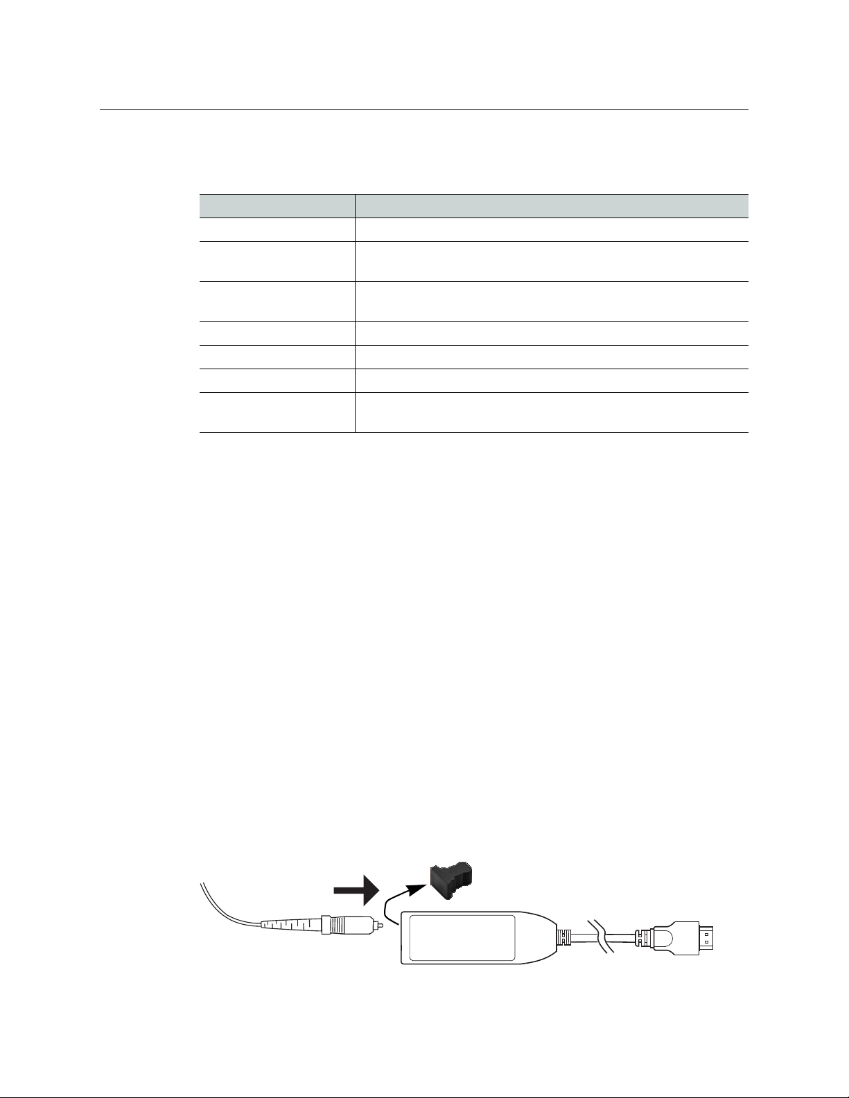
2 If transmission stops unexpectedly and the transmitter is powered by the video
source’s HDMI connection, change the transmitter’s power source: connect the micro-
USB B plug of the USB cable to the DXF-4K transmitter’s power input jack and connect
the other end of the USB cable to a USB power source such as an unused USB jack on
the video source or to the supplied power supply. If used, plug-in the power supply to
an outlet (mains).
3 Make sure the fiber connectors are clean, as the problem is often related to dust
obstructing the light at the fiber connections.
4 Use another fiber connection.
5 Swap components of the DXF-4K kit with known working components, one
component at a time in a systematic fashion to further isolate the issue. For example,
swap the transmitter module, then swap the receiver module, and so on.
Firmware Upgrade
The firmware in the DXF-4K transmitter / receiver can be upgraded in the field. Only one
module can be upgraded at a time (transmitter or receiver). The following is required to
proceed:
• A Microsoft Windows PC that has:
• an available USB A port
• Internet connectivity
• Firmware image files; one for the transmitter module and one for the receiver module
• USB BootLoader firmware upgrade software
• USB cable, male USB A to male micro-USB B
Procedure to Connect to a Module
1UnziptheUSB BootLoader.zip file.
2 Double click the HIDBootloader vX.X.X.exe file to launch the USB BootLoader firmware
upgrade software.
3 Disconnect the optical fiber from the module.
4 Connect the micro-USB B plug of the USB cable to the DXF-4K receiver’s power input
jack and connect the other end of the USB cable to an available USB Port on your PC.
Note: Only one module may be connected to the PC at a time.
5 Wait for USB BootLoader’s connection confirmation. The receiver or transmitter module
should show solid Pink LED. The USB BootLoader Interface should have one of TX or RX
status buttons illuminated at the bottom of its Interface Window.

9
DXF-4K
Installation Guide
Procedure to Identify the Module’s Current Firmware Version
1 With USB BootLoader connected to the receiver or transmitter module (see above),
select Display User ID in the Program menu.
2 The USB BootLoader Interface will show the User ID in the Text Window as 4 numbers
as follows: 81. 2.1.6. The last3 numbers in this 4 digit sequence represent the version
number. In this case, the version number would be v2.1.6.
Procedure to Update the Module’s Firmware
1 With USB BootLoader connected to the receiver or transmitter module (see Procedure
to Connect to a Module, on page 8), click the File menu.
2 Up to 3 recently loaded files will be displayed in this menu. Select one of these files if
desired and skip to step 5. Otherwise…
3 Select Import Firmware Image. This will cause a standard windows File Selection
Window to open.
4 Use the File Selection Window to locate and select the Firmware Image file. Note:
Please be sure to select RX Firmware for an RX Module and TX Firmware for a TX
Module.
5 When the new firmware is loaded, the USB BootLoader Interface should display the
current (pre-update) module ID and the new module ID (Post Update) in the Text
Window. Note: At this point, the Update Firmware has only be loaded in to the USB
BootLoader Interface. In a following step, you will still need to program the Module.
6 Select Erase/Program/Verify Device in the Program menu.
7 Wait for the module programming operation to complete. This may take a few seconds.
8VerifythatProgramming Success is reported in the Text Window.
9 Select Reset Device in the Program pull down menu.
10 Wait for the Reset Operation to complete and for the Module to reconnect to the USB
BootLoader Interface.
11 Select Display User ID in the Program menu
12 The USB BootLoader Interface will show the User ID in the Text Window as 4 numbers
as follows: 81. 2.1.6. The last3 numbers in this 4 digit sequence represent the version
number. In this case, the version number would be v2.1.6.
Specifications
DXF-4K Transmitter / Receiver:
• Transmission:
• HDCP 2.2 and HDCP 1.4 content protection support
• Full UHD 4K 4:4:4 with HDR, 60 frames per second support
•Operatingstatus:
•MulticolorLED.SeeStatus Indicator Interpretation, on page 5.
•Fiber:
• Link bandwidth: 18 Gbps
• Type: OM4 Multimode fiber (MMF), Single fiber cable (field supplied)

10
DXF-4K Installation Guide
Specifications
• Connector type: SC
• Maximum fiber length: <1000m.
Maximum fiber length supported depends on quality of the fiber deployed.
1000m based on OM4 having 6000 MHz-km bandwidth and typical coupling
and transmitter and receiver optical performance limits.
•HDMIInterfaces:
• Connector: HDMI type A
• HDMI 2.x and HDMI 1.x automatic selection based on the video source
• Consumer Electronics Control (CEC) over HDMI support.
• The HDMI connection can power the transmitter if the source equipment is
capable.
•USBInterface:
• Powers the receiver from the included power supply or from an unused USB
plug on the display
• Powers the transmitter (when the HDMI connection does not do so) from the
included power supply or from an unused USB plug on the video source
equipment
• Permits firmware upgrades
•Electrical
• Supply Voltage: 4.75 to 5.25 Vdc
• Transmitter Supply Current: 400mA
• Receiver Supply Current: 250mA
•Environmental
• Weight: 0.15lb (65g)
• Dimensions: See Optical Extender Overview, on page 4.
• Operating Temperature Range: 32 to 122°F [0 to 50°C]
• Storage temperature range: -40 to 185°F (-40 to 85°C)
• User safety: when an open fiber condition is detected, the lasers are turned off.
•Compliance
• FCC Part 15 Class B for Susceptibility, Radiated and Conducted
• CE for Susceptibility, Radiated and Conducted
• Optical Fiber Communication System Class 1 Eye Safety per IEC 60825-1
• IEC 60825-1:2014-05 Ed. 3.0
•FDACDRH
Power Supply:
• Wall plug universal power supply
•Electrical
• Input: 90 to 264 VAC, 47 to 63 Hz
•Environmental
•Each power supply includes four plug adapters for UK, US, AU, and EU
• Weight (body only): 0.17lb (80g)

11
DXF-4K
Installation Guide
• Dimensions (nominal, plugged in to a socket):
– W 1.45 [37.0] × L 2.16 [55.1] × H 1.96” [49.9mm] UK
– W 1.45 [37.0] × L 2.16 [55.1] × H 1.93” [48.9mm] US
– W 1.45 [37.0] × L 2.16 [55.1] × H 2.11” [53.7mm] AU
– W 1.45 [37.0] × L 2.16 [55.1] × H 2.60” [65.9mm] EU
• Operating temperature range: 32 to 140°F (0 to 60°C)
• Storage temperature range: -40 to 185°F (-40 to 85°C)
• Operating humidity range: 5 to 95% relative humidity, non-condensing
• Safety approvals:
• CB Report (IEC60950-1)
• UL (UL/cUL60950-1, approved as limited power source (LPS))
• TUV (EN60950-1)
USB Cable:
• Length: 6 foot (1.8M) cable
• Connectors: male USB A to male micro-USB B

Contact Us
Grass Valley Technical Support
For technical assistance, contact our international support center, at
1-800-547-8949 (US and Canada) or +1 530 478 4148.
To obtain a local phone number for the support center nearest you, please consult the
Contact Us section of Grass Valley’s website (www.grassvalley.com).
An online form for e-mail contact is also available from the website.
Corporate Head Office
Grass Valley
3499 Douglas-B.-Floreani
St-Laurent, Quebec H4S 2C6
Canada
Telephone: +1 514 333 1772
Fax: +1 514 333 9828
www.grassvalley.com
Table of contents
Other Belden Extender manuals