BelFone BF-TR8500 User manual
www.belfone.com
-TR8500
Professional DMR Repeater


Acknowledgement!
Notice to the user
Thank you for choosing BelFone series professional radio communication
products!
Since 1989, BelFone has been dedicated to research and exploration in the
field of radio communication technology throughout the decades, and has
developed leading smart technology in the industry. Underpinned by research,
development and design geared towards modern complicated and
changeable communication environment, it is capable of tailoring specific
communication solutions to your needs based on features of your industry.
Superior products with outstanding performance may help you control the
overall situation, while providing you with the best choice for smart scheduling
and instructions communicating.
This User Manual is applicable to:
BF-TR8500 Series all of frequency band
Government law prohibits the operation of unlicensed radio transmitters
within the territories under government control.
Illegal operation is punishable by fine or imprisonment or both.

Instructions before Use
Following the safety precautions below may prevent damage to this
product and personal injuries. To avoid potential risks, please read these
instructions carefully before using the product, and operate the product
as instructed.
◆ The repeater shall be protected from long-time direct exposure to the sun,
kept in a place away from high temperature, high humidity, high dustiness or
water splashes, and put on a stable surface;
◆ Where use of the repeater is prohibited or use of intercommunication may
cause interference or danger, the repeater shall have its power turned off as
required by relevant regulations;
◆ If you find any fault of the product, please turn off the power directly, and
then contact the local distributor of BelFone; unless otherwise specified in this
Manual, maintenance shall not be performed by any person other than a
maintenance worker authorized by BelFone Company;
◆ If this product is needed for further development, please contact BelFone
Company or BelFone's distributor;
◆ Do maintain the product surface clean and dry; for cleaning, use a piece of
soft cloth dipped with mild detergent or clear water (without water dripping) to
wipe the product surface.

Content
Unpacking and Device Inspection .............................................. 01
Standard Accessory....................................................................... 01
Optional Accessory........................................................................ 01
Features ....................................................................................... 01
Get Familiar with the Device........................................................ 02
Front Panel View ........................................................................... 02
Indicator Status.............................................................................. 03
Back Panel view ............................................................................ 04
Basic Operations ......................................................................... 05
Power on/off .................................................................................. 05
Button Configuration ...................................................................... 05
Functions and operation instructions......................................... 07
Digital Mode .................................................................................. 07
Analog Mode Function................................................................... 09
Smart Digital-Analog Switch........................................................... 09
Back-to-Back Function................................................................... 09
Simulcast Function ........................................................................ 09

Positioning Service ........................................................................ 09
Technical Specifications ............................................................. 10
Statement..................................................................................... 12

Unpacking and Device Inspection
Note: The following instructions regarding unpacking are only for BelFone’s
distributors, and service agencies or factories authorized by BelFone.
Be careful when taking the device out of the packing box. You’d better count the
accessories against the following list before discarding the packaging. If you find
any item is missing or damaged, please contact the local distributor of BelFone or
directly contact BelFone Communication immediately.
Standard Accessory
Quantity
1
1
1
1
1
Item
Main Equipment
Power Cord
Operationing Manual
Warranty Card
Conformity Certificate
Optional Accessory
Quantity
1
1
1
1
Item
Duplexer
DC Power Cord
Position Antenna
programming Cord
Features
●Dual Mode(Analog & Digital) Repeater Function
●Support digital, analog and analog digital auto-switch
●Support customization, work with BelFone Intelligent IP interconnection system
●Support customization, IP Multi-site Connect
●Support customization, work as Simulcast Base Station
●Support GPS+BD Satellite Positioning
●Over voltage, over temperature alarm and protection
●Switching High, Middle and Low TX power. 01
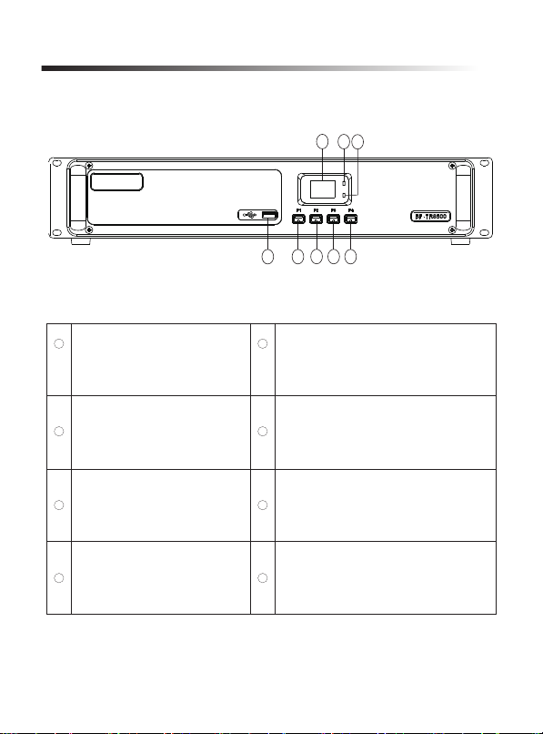
Front Panel View
Get Familiar with the Device
123
4568
7
LCD
A Indicator: Timeslot 1 working
state indication
B Indicator: Timeslot 2 working
state indication
USB Port
1
2
3
4
5
6
7
8
P1: Short press to decrease the channel
number, long press to display IP address;
(programming supported)
P2: Short press to increase the channel
number, long press to display version
(programming supported)
P3: Short press to display TX frequency,
long press to display IP internet site type;
(programming supported)
P4: Short press to display RX frequency,
long press to display IP interconnection
status. (programming supported)
02

Indicator Status
LED Indication
A Indicator
Normally on
in orange
Green light
flickers (1s)
Orange light
flickers (1s)
Orange light
flickers (1s)
Red light flickers
quickly (0.5s)
Red light flickers
slowly (2s)
Orange light
flickers (1s)
Orange light
flickers (1s)
Green light
flashes quickly
(0.5s)
Green light
flickers slowly (2s)
Normally on
in orange
Flashing in
red (1s)
Channel Number
Channel Number
Channel Number
Channel Number
Timeslot 1 emission
Analog receiving
Timeslot 2 emission
Analog transmission
/
/
E0
E1
E2
E3
E4
E5
E6
PLL receiving
abnormality
PLL transmitting
abnormality
Excessively
high voltage
Excessively
low voltage
Excessively
high temperature
Fan working
abnormality
The network is
unconnected or
abnormal
/
/
/
/
/
/
/
/
B Indicator
LCD Display Device State
03
9
10 11 12 1413 15 16
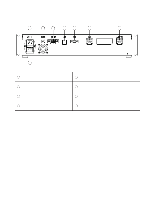
Back Panel view
Power Switch
AC Power Input Port
GPS Antenna Port
DC Power Input Port
Network Port
ACC Accessory Unit Port
RX RF Input Port
TX RF Output Port
9
10
11
12
14
13
15
16
04
Power on/off
Press the [power switch] on the back of the repeater, the screen will light up and
the LCD will display the channel number; and press the [power switch] again, the
screen will go dark and the device is shut down.
Button Configuration
Use the programming software to configure P1~P4 key, while corresponding the
P1,P2,P3,P4 key to short pressing and holding-down operations.
Programmable buttons include the following functions:
1. Undefined: No function is assigned to the programmable button;
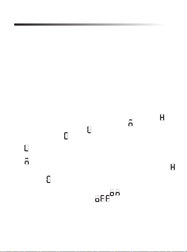
2. Power Switch: Press it to quickly switch the transmitting power: Low, Meddle,
High, user-defined, when switching to high power, the LCD will display icon: ;
when switching to meddle power, the LCD will display icon: , when switching to
low power, the LCD will display icon: , when switching to Self-Defined power,
the LCD will display icon: ;
3. Low Power: Press this button to switch to lower power, the LCD will display
icon: ;
4. Middle Power: Press this button to switch to medium power, the LCD will display
icon: ;
5. High Power: Press this button to switch to high power, the LCD will display icon:
6. Self-Define Power: Press this button to switch to a Self-Defined power, the LCD
will display icon: ;
7. Tone Alerts: Press this button to turn on or off the prompt tone, when turn on the
prompt tone, the LCD will show the following icon: , when turn off the prompt
tone, the LCD will show the following icon: ;
8. Channel+:Press this button to switch the channel - the channel number will
progressively increase
9. Channel-:Press this button to switch the channel - the channel number will
progressively decrease
Basic Operations
05

10. Back-to-Back Switch:Press this button to turn on/off the back-to-back switch,
when turn on the Back-to-Back, the LCD will show the following icon: , when
turn off the Back-to-Back, the LCD will show the following icon: ;
11. Satellite Positioning Switch: Press this button to turn on/off the position switch,
when turn on the satellite positioning, the LCD will show the following icon: ,
when turn off the satellite positioning, the LCD will show the following icon: ;
12. Display Version: Press this button to view the version, the LCD will scroll show
the version number;
13. Display IP Address: Press this button to view IP address, the LCD will scroll
show the IP address;
14. Display IP internet site type: Press this button to view the IP internet site type,
if the connection type is None, the LCD show the icon: - ; if the connection type
is: Peer, the LCD show the icon: - ; if the connection type is: Backup Main Site,
the LCD show the icon: - ; if the connection type is: Home Station, the LCD
show the icon: - .
15. Display IP interconnection status: Press this button to view the IP
interconnection status, if the interconnection function disable, the LCD show the
icon: - , if the connection type is Home Station, the LCD show the number of
connected slave repeater; if the connection type is Backup main site, the LCD
show the icon:- .
16. Display TX Frequency: Press this button to view TX Frequency of current
channel;
17. Display RX Frequency: Press this button to view RX Frequency of current
channel;
18. Display GPS Satellite Info: Press this button to view GPS Satellite information,
and the first value shows 0 means GPS unsynchronized, shows 1means GPS
synchronized; the second value shows the number of satellite.(Hex digits:1~F, and
the F means the satellites are fifteen or more)
19. Squelch Adjustment -: Press this button to adjust squelch level, the LCD show
the squelch level of current channel, and then press again the value progressively
increase;
20. Squelch Adjustment +: Press this button to adjust squelch level, the LCD show
the squelch level of current channel, and then press again the value progressively
decrease.
Note: While the LCD scroll shows the values and last digit will show repeatedly.
06

Digital Mode
Network Setting
1. Digital Repeater Mode
If the current channel operation in the repeater mode, if the repeater is
transmitting in timeslot 1, indicator A will glow orange, and if the repeater is
transmitting in timeslot 2, indicator B will glow orange.
2. IP Interconnection Mode
Digital mode supports IP multi-site connection, and may realize interconnection
between IP sites of multiple repeaters. When programming software is used to
configure network services with one master repeater and multiple slave repeaters,
it is required to configure a timeslot to the IP interconnection mode, so that after
the network is connected, services may be transmitted from one repeater to the
other repeaters.
Master Station:
In an IP multi-site connect system, it is permitted to configure only one master
repeater, while other repeaters shall be configured as slave repeater, with IP
addresses registered with the master repeater for IP interconnection.
Backup Master Repeater:
The backup master repeater is a slave repeater. In a system, it is permitted to
configure a backup master repeater, which in normal operating conditions is the
same with other slave repeaters. Only when the master repeater fails and cannot
be connected, the backup master repeater will act to play the role of a master
repeater in lieu of the original master repeater for registration of other slave
Functions and operation instructions
Function
IP interconnection function is disabled
Set to slave (registration of the master repeater required)
Set to master (waiting for slave repeater registration)
A type of slave repeater that will automatically become a master
repeater when the master repeater fails.
Connection type
None
Peer
Master Station
Master Repeater
Backup
07

3. System Networking Function
The repeater can be connected to BelFone intelligent interconnection system
(SDC), and supports access to the system network for repeating DMR digital
voice and data services, so as to realize interconnected communication in the
networked mode.
Note: System networking is optional.
repeaters.
Peer:
An peer is a slave repeater, in a system, it is permitted to configure multiple slave
repeaters. Upon programming software, it is required to configure slave
repeaters, the backup master repeater and the current repeater’s IP address for
successful registration with the master repeater.
Authorization Code: Peers shall have consistent authorization codes with the
master repeater for successful registration. For an authorization code, it is allowed
to enter a maximum of 16 digits and letters from 0~9 and A~F; it can be null if
nothing is entered.
DHCP: When a peer is set to DHCP, the router will act as the DHCP server and
automatically assign an IP address to the peer.
(The router shall support DHCP, and the IP address assigned shall be within the
same network segment of the master repeater’s IP).
● When the current repeater is connected as a master repeater, it is required to
configure its IP, UDP port, gateway IP, network mask, NDS server IP, UDP port;
● When the current repeater is connected as a backup master repeater, it is
required to configure its IP, UDP port, gateway IP, network mask, DNS server IP,
UDP port and master repeater IP, master repeater UDP port;
● When the current repeater is connected as an peer, it is required to configure its
IP, UDP port, gateway IP, network mask, DNS server IP, UDP port and master
repeater IP, master repeater UDP port, backup master repeater IP, backup
master repeater UDP port.
Note: In one system, only one “master repeater” and one “backup master repeater” are
permitted; other repeaters shall be configured as “peers”.
The function is optional.
08

Analog Mode Function
If the channel operates in the analog repeater mode, and the current channel
currently has any voice service under repeating, indicator A will flash green,
indicator B will flash red.
Smart Digital-Analog Switch
This repeater supports digital and analog channel auto switching, it can smartly
select the right one based on the type of received signal and then transmitting.
Back-to-Back Function
The repeater supports the back-to-back function to realize back-to-back
connection between a single repeater and other device for repeating voice. The
current device supports back-to-back connection of digital channels and that of
analog channels. The back-to-back function can be set via the programming
software or the preprogrammed [Back to back Switch] key.
Note: Back-to-back connection of analog channels requires the GPIO BUSY line set via
the programming software to output an active level and the PTT line to input an active
level. The “active level output by the BUSY line” of the current device shall be the same
with the “active level input by the PTT line” of the other back-to-back device.
Simulcast Function
The repeater supports Simulcast function. When the Simulcast function is
enabled, the repeater can be registered as an peer with the base station
controller of BelFone intelligent interconnection system to realize networking of
Simulcast function.
Note: Simulcast function is optional.
Positioning Service
The repeater supports satellite positioning, and can have the positioning type set
via a programming software to: GPS/BD/GPS+BD. The position switch can be set
via the programming software or the preprogrammed [Satellite Positioning Switch]
key. When GPS is enabled, the LCD will show icon: , When GPS is
disabled, the LCD will show icon:
09

General
Emission
Frequency Range
Number of Channels
Channel Spacing
Antenna Impedance
Backup Power Supply
Current Consumption
Operating Environment
Storage Temperature
Sizes
Weight
11-13.8VDC,9A
< 9A
-30℃~+70℃
-40℃~+85℃
441mm(L)*327.5 mm(W)* 88(H)
11.8Kg
99
12.5KHz
50Ω
Technical Specifications
VHF:150MHz
UHF:350MHz/400MHz/450MHz
RF Power 5-50W(Continuous Emission)
Power of Adjacent Channel ≤60dB
Master Power Supply 85-132VAC/170-264VAC(by switching),
47-63Hz,3A/115VAC,1.7A/230VAC
Frequency Stability ≤±0.5ppm(Without Positioning)
≤±0.02ppm(With Positioning)
4FSK Digital Modulation 12.5KHz only data:7K60FXD
12.5KHz data and voice:7K60FXW
Spurious Emission -36dBm<1GHz
-30dBm>1GHz
10

Receiving
Sensitivity
Frequency Stability
Adjacent Channel Selectivity
Intermodulation Immunity
Spurious Response
Blocking
≥60dB
≥70dB
≥70dB
≥95dB
3%BER≤0.35µV
≤±0.5ppm(Without Positioning)
≤±0.02ppm(With Positioning)
11

To the best of our knowledge, this Manual has been prepared in an accurate and
complete manner. For any doubt, please contact us timely for specific
explanation. Considering the fast development of wireless communication
technology, BelFone reserves the right to modify the product design and
specification without any further notification. Your understanding in this respect
will be much appreciated!
12


Add: A-15 Huaqiao Economic Development Zone,
Shuangyang,Luojiang,Quanzhou,Fujian,China
Tel: +86 595 28396717
Fax: +86 595 22771635
Email: [email protected]
Website: www.belfone.com
Table of contents


