Beliani RS200 Quick setup guide
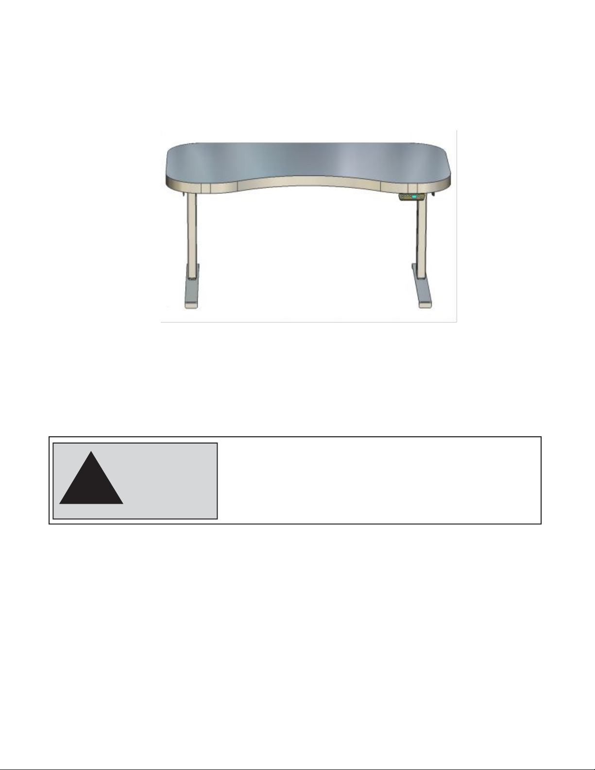
ELECTRIC HEIGHT ADJUSTABLE DESK
RS200 Standing Desk
DIRECTIONS FOR ASSEMBLY AND USE
!
CAUTION
MAKE SURE NO OBSTACLES ARE IN THE DESK’S PATH AND
ALL CORDS ARE OF APPROPRIATE LENGTH FOR DESK
TRAVEL. FAILURE TO COMPLY WITH OR OBSERVE ALL
ASSEMBLY, SAFETY, AND OPERATION INSTRUCTIONS AND
WARNINGS REGARDING THE USE OF THIS PRODUCT MAY
RESULT IN SERIOUS PROPERTY DAMAGE OR BODILY INJURY.
IMPORTANT:
Any user or installer of desk base must study this manual carefully.
If this desk is sold, please provide the manual to the buyer.
1

2
TABLE OF CONTENTS PAGE
1.
SAFETYANDWARNINGS 2
2.
USAGE
2
3.
SETUPANDINSTALLATION 2
4.
PARTS LIST 3
5.
ASSEMBLY INSTRUCTIONS 4
6.
TECHNICAL SPECIFICATIONS 9
7.
TROUBLESHOOTING GUIDE 9
1.
SAFETY AND WARNINGS
•
•
•
•
Inappropriate use of this product may cause property or bodily injury.
Checksurroundingsonallsidesbeforeusingthedesk.Bodypartsandproperty
can be crushedif trapped between an immobile obstacle and the desk’s range of motion.
Ensure the length of power cords are accountedfor whenoperating the desk. Monitors,
computers,speakers,anything witha cord that is notlong enoughfor thedesk’s range
of motioncould be pulled down or haveits wires broken.Items pulled off the desk
maycauseotheritemsto fall.
Pleaseprovidethisoperationtoanyusers,installers,orsupportpersonneloperating
the product.
2.
USAGE
Thisheightadjustabledeskhasanelectricmotorandis designedforuseindry workareasonly.
The desk height is adjustableso that it can be positionedat the most ergonomicallysuitable height. These
desksaredesignedonlyforthepurposesincludedinthismanual.Theyshouldnotbeused
inenvironmentswithhighhumidityordampness.Anyotheruseis atuser’s risk.
Do notmove around,crawl or lie underthe desk frame. Do notsitor standon the desk frame.
Childrenshouldneverusethedeskunlesstheyaresupervisedbyadults.
Liability: Under nocircumstances doesthe manufacturer acceptwarranty claims or liability claims
for damages caused from improper use or handling of the desk frame other than that which
isdescribedinthisoperationmanual.
3.
SETUP AND INSTALLATION
Oncethedeskhasbeenassembled,adjustthefeetsothat thedeskis levelanddoesnotshiftitsposition.
Afterthis, connect the deskto the110v or 230voutletandthe desk isreadyforuse.
Checkthatnocablescangetjammed.
Choosea placementforthe deskthat’sa safe distancefrom windowframes,radiators, furnitureetc.so
that people do not get stuck or trapped by the desk.
Do not place any objects that are taller than 20” underneaththe desk.
After it has been assembled, when movingthe desk,DO NOT lift the deskby the desktop. Lifting
this way can stress the fasteners connectingthe deskbaseto the desktop. Lowerthe deskcompletelyand
lift the desk by grabbing the top of the desk base or by removing the desktop first.

3
Tools
Required
Allen
Wrench(included)
Tape
Measure
Philips
Head Screwdriver, and/or Power Drill
4.
PARTS LIST
Components
Qty 2 Legs Qty 2 Feet Qty 4 Crossbar end Qty 2 Crossbar center Rails
Qty2 Side Brackets Qty 1 control box Qty 1 Keypad Qty 1 power cord
Qty 4 Leveling Studs

4
Pleasecountallpiecesbeforedisposingofanycartonorpackingmaterial.Usea paddedorcarpeted
areaforassemblytoavoiddamage.Foreaseandsafety,werecommendtwopeopleforassembly.
Hardware
Machine Screws Pan Head Screws
4mm 1PC M6*25 20PCS M6*40 8PCS M6*10 4PCS M5*16 2PCS M5*45 2PCS 10PCS
5
5.
ASSEMBLY INSTRUCTIONS
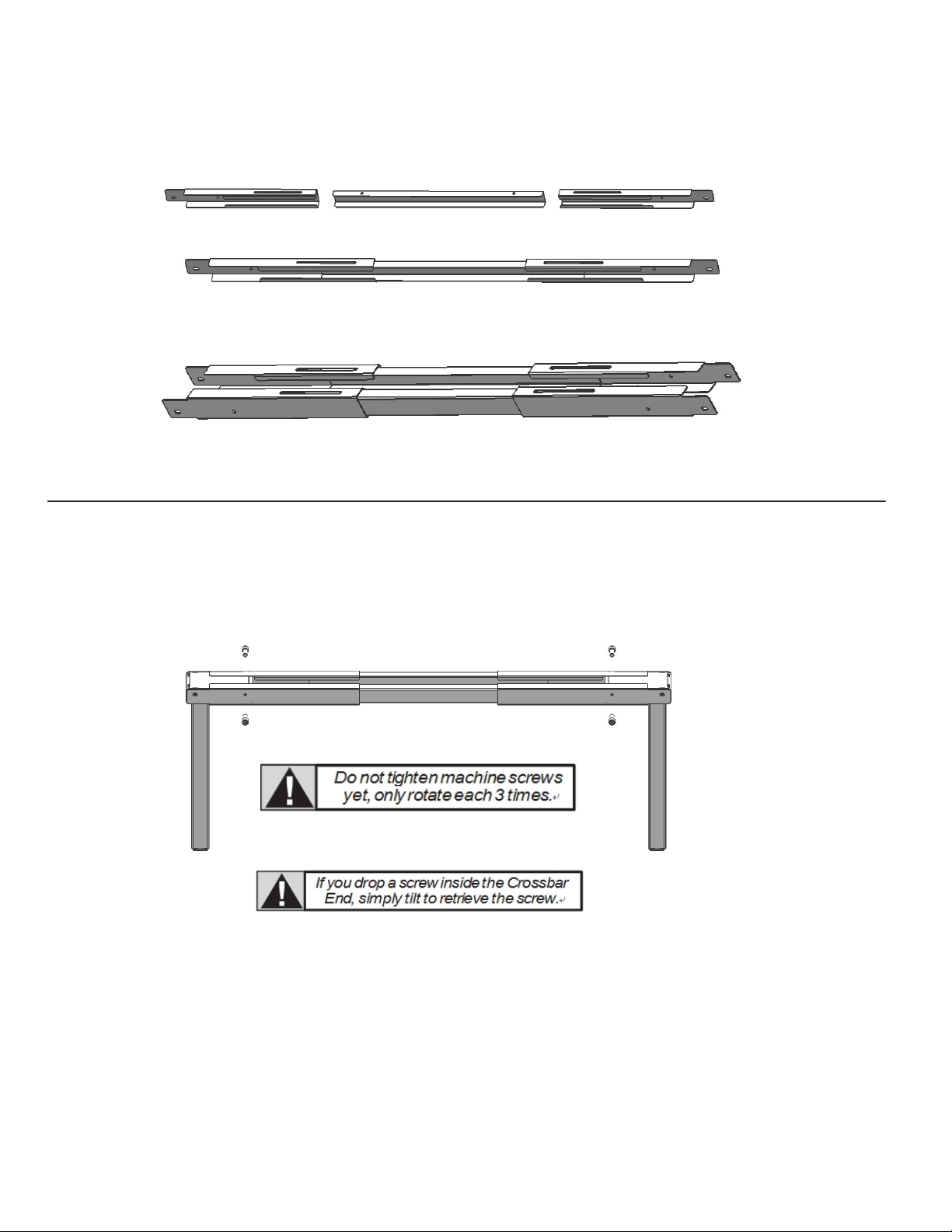
A.
First, Lay out all components and hardwareto ensure that you have all the parts listed on the compo-
nents list. Then Slide Crossbar CenterRails (Part #4) out of Crossbar Ends(Part #3).
L
i
n
e
u
p
t
h
e
h
o
l
e
s
o
n
e
a
c
h L
e
g
(
P
a
r
t
#
1
)
with the holes on each Crossbar End (Part #3
).
B.
IMPORTANT! DO NOT TIGHTEN SCREWS IN THIS STEP, ONLY INSERT THEM
AND ROTATE 3 TIMES. YOU WILL TIGHTEN IN STEP D.
I
n
s
e
r
t
q
t
y
4
Ma
c
h
i
n
e
S
c
r
e
w
s
(
P
a
r
t
#
11
)
t
h
r
o
u
g
h
t
h
e
4
h
o
l
e
s
o
f
e
a
c
h
C
r
o
ss
b
a
r
E
n
d
(
P
a
r
t
#
3
)
g
o
i
n
g i
n
t
o
t
h
e
L
e
g
(
P
a
r
t
#
1
)
.
U
s
i
n
g
t
h
e
All
e
n
W
r
e
n
c
h
,
r
o
t
a
t
e e
a
c
h
s
c
r
e
w
ON
L
Y
3
t
i
m
e
s
.

6
C.
IMPORTANT! DO NOT TIGHTEN SCREWS IN THIS STEP, ONLY INSERT THEM
AND ROTATE 3 TIMES. YOU WILL TIGHTEN IN STEP D.
11
Line up the 2 holes on the Side Brackets (Part #5) with
theCrossbarEndandLegassemblyfromthepreviousstep.
5
I
n
s
e
r
t
q
t
y
4
Ma
c
h
i
n
e
S
c
r
e
w
s
(
P
a
r
t
#
11
)
t
h
r
o
u
g
h
the 2 holes of the Side Bracket (Part #5) going into
theCrossbarEnd/LegAssembly.Usingthe
Allen Wrench, rotate each screw ONLY 3 times.
3
D.
O
n
c
e
a
ll
o
f
t
h
e
s
e
s
c
r
e
w
s
h
a
v
e
b
ee
n
s
t
a
r
t
e
d
,
y
o
u
c
a
n n
o
w
t
ig
h
t
e
n
t
h
e
q
t
y
8
Ma
c
h
i
n
e
S
c
r
e
w
s
f
r
o
m
S
t
e
p
C
a
n
d
t
h
e
q
t
y
4
Ma
c
h
i
n
e
S
c
r
e
w
s
d
e
s
c
r
ib
e
d i
n
S
t
e
p
B
(
1
2
s
c
r
e
w
s
i
n
t
o
t
a
l
)
.
If you are having trouble getting all the
started, it is because other screws are too tight.
You’ll need to backout somescrews in order
to loosen the toleranceof thescrew holes.
7
E.
The Crossbar CenterRails (Part#4) are optional. They provide more stability but if not neededthey
can be skipped during installation or removed later.
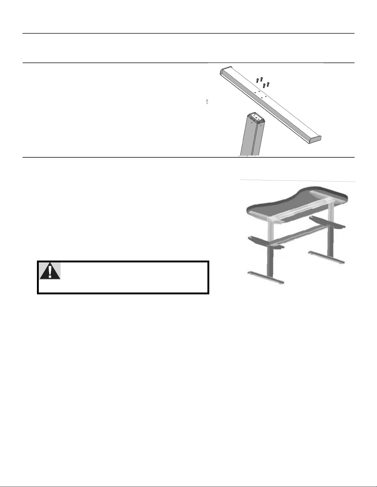
F.
AttacheachFoot(Part#2)
11
wi
t
h
q
t
y
4
Ma
c
h
i
n
e
S
c
r
e
w
s
and tighten bolts in a cross pattern.
2
1
G.
Your desktopmay or may not be pre-drilled. Please check both sides of the desktop before
placingthe deskbase on it for pre-drilling! Carefullyplace the upsidedown deskbaseon the
undersideof the desktop.
Note: minimum top size: 43” wide x 24” deep
Adjustthewidthofthebasetofitthedesktopbysliding
the
two
halves
outward
(42.125”
to
74.75” max).
Placethebasewhereyouwantit.Somewillwanttheframetobeall
the
way
to
the
edge
of
the
desk.
We
recommendleaving
at
least
1/2”
ofdesktopwidth(oneachside)protrudingbeyondtheframewidth.
Center the frame by using the desktopedge
asa reference. Measuretothemetalbrace.
Do not use the screw holes as a point ofreference.
Thedeskfeetare deeperthanthe sidebrackets.
If your top is 25.5”-27.5” deep and you want the
rear edge of the top in line with the rear edges
of the feet, offset your desktop toward the back.
8
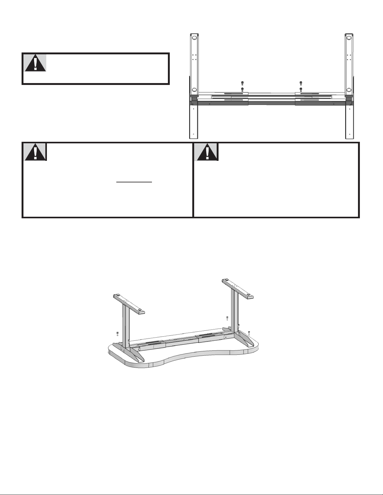
H.
SecuretheCenterRailsatbothends
using
qty
4
MachineScrews
,
qty 4 per
side. Maximum width is 70”.
12
Ensurethatthemachinescrew
hits the metal center rail by sliding
thecenterrailasneeded.
I. Double-check that the base is centered on the underside of the desktop and is located where you
want it. Also, double-check that the included wood screws are not too long for your desktop and won’t
puncturethe surface whenscrewedallthewayin.
Werecommendyoupre-drillany
holes neededforfasteners
connecting
Never use countersunk
screws
to fasten into the
desktop.
thebasetothetop.
NOTE:
PLEASE ENSURE THAT YOUR
DESKTOP DOES NOT
ALREADY
HAVE
HOLESBYCHECKINGBOTHSIDES.
Thiswill make it easier to attach the screws
andwillgreatlylessenthestresscausedby
drivinga screwintothe desktop material.
This will cause much greaterstress
onthedesktop.Ensureanyscrewused
will not puncture through the desktop
surface orotherwisedamagethematerial.
Now, proceed with securing the desk base to the desktop using qty 6 of the larger Pan Head Screws.
Install as follows:
3 per side bracket (left)
3 per side bracket (Right)
J.
IN THIS FOLLOWING STEP, DO NOT OVERTIGHTEN SCREWS. OVER TIGHTENING MAY
CAUSE THE PLASTIC ON THE COMPONENTS TO BREAK.

9
K.
Werecommendyoupre-drillanyholes
neededforfastenersconnectingthe
Neverusecountersunkscrewstofasten
intothedesktop.Thiswillcausemuch
ControlBoxtothetop.Thiswillmake
it easierto attach the screws and will greatly
lessenthestresscausedbydrivinga screw
into the desktop material.
greaterstressonthedesktop.Ensure
any screwusedwillnotpuncturethrough
thedesktopsurfaceorotherwisedamage
thematerial.
Use
qty
2
of
the
smaller
Pan
Head Screws
to attach
the Control Box (Part #6). Ensure enough
clearance atthe wire portsforcableconnections.

7
L.
IN THIS FOLLOWING STEP, DO NOT OVERTIGHTEN SCREWS. OVER TIGHTENING MAY
CAUSE THE PLASTIC ON THE COMPONENTS TO BREAK.
Place the Keypad(Part #7) so the frontof the keypad runs flush
with
the
desktop
edge
(or
recessed
up
to
1/8”).
The
Keypad
can
be placed anywhere along the front edge of the desk, but we
recommend placing it near the side so it doesn’t interfere with
yourchairorlegswhenseated.
Use
qty
2
of
the
smaller
Pan
HeadScrews
to
attach
the
Keypad (Part #7) to the desktop.
M.
Connect
the
Wires
as
per
the
diagram
below.
Use
the
adhesive-backed Cable Clips
(Part
#14)
to
secure the Connecting Wires, so they don’t sag.
N.
Turn the assembleddesk right-side-up.With two people, grab the desk by the base(not the desk-
top) and turnthe desk right-side up. Adjustthe Leveling Studs on the Feet (Part#2) as needed.
MAKE SURE NO OBSTACLES ARE IN THE DESK’S PATH.
MAKE SURE ALL CORDS ARE OF A LENGTH THAT WILL
ACCOMMODATE THE CHANGE IN HEIGHT.
O. Plug the Power Cord into a 110v or230v or 240v outlet.
IMPORTANT!
You must RESET the deskprior to use:
Pressand hold the DOWNbutton on the Keypad

8
untilthedeskreachesitslowestheight.Releasethe
DOWN button. Press and hold the DOWN button
againuntiltheLEDdisplayreads“ASF”orabout10
secondsonnon-LEDhandsetmodels.Releasethe
DOWN button. Press and hold the DOWN button
again until the desk lowers a little bit more, slightly
risesandstops.ReleasetheDOWNbutton.
Yourdeskis nowreadytouse.
To program up to four presets:
Use the up/down buttons to find a desired height, then press “S” followed by a number
1
–4.

9
6.
TECHNICAL SPECIFICATIONS
7.
TROUBLESHOOTING
--Reset Instructions--
If experiencingerror messages showing on the keypad or no response when tryingto raise or lower:
•
Unplug the power cord and hold the down key for 20 seconds.
•
Plug the power cord back in.
•
Press and hold the DOWN button on the Keypaduntil the desk reaches its lowestheight.
ReleasetheDOWNbutton.PressandholdtheDOWNbuttonagainuntiltheLED
displayreads“AST”orabout10secondsonnon-LEDhandsetmodels.ReleasetheDOWN
button. Press and hold the DOWN button again until the desk lowers a little bit more, slightly
risesandstops.ReleasetheDOWNbutton.Yourdeskisnowreadytouse.
•
The keypad will then display the current height, and you should be able to operate it now.
•
You may need to do this if the desktop is ever unplugged or loses power.
If
the
handset
displays
error
messages
“E07”
thru
“E08”,
confirm
that
all
wired
connections
are
secure
(legs
to cables, cables to control box). Then perform the reset procedureabove. If the error messagepersists
afterthe reset procedureof if the heightbetween the legsexceeds 1.5 inches stop thereset procedureand
contact Ruishi office
.
If the handset displays “Hot”, let the base cool down for 20 minutes.
If thedeskseemstobeuneven,trytheresetinstructionsabove.Ifthatdoesnotworkyoumay
need toadjustthelevelersatthebottomofthefoot.
In the event of a power outage or if the power cord is unplugged,
amanualresetmaybenecessary(seeResetInstructionsabove)
This product is designed with a duty cycle of 10%
(2 min. on, 18 min. off)
KeepChildrenawayfromelectricheight-adjustabledesks,control
unitsandhandsets.Thereisa riskofinjuryandelectricshock
Do not open any of the components: lifting columns, control box, or
handset.Thereisa dangerofelectricshock
Keepall electricalcomponentsawayfromliquids
Height Range
23.4”–48.6”(withoutdesktop)
BaseWidth
43.3
”
m
i
n
–
55.1
”
m
a
x
Travel Speed
1.5” per
s
e
c
o
n
d
(
v
a
r
i
e
s
,
s
l
o
w
e
s
t
w
/
m
a
x
i
m
u
m
l
o
a
d
)
Weight Capacity
353 lbs.
Duty Cycle
10%, Max. 2 mins on, 18 mins off
4 Memory position in the handset
0.1W standby power ecofriendly
Anti-collision technology to prevent damage
Adjustable desk frame
i
i
Table of contents
Other Beliani Indoor Furnishing manuals


Popular Indoor Furnishing manuals by other brands

ADIROffice
ADIROffice Four Tier Locker user guide

Safavieh Furniture
Safavieh Furniture Marka MCR1004 quick start guide

ATAN
ATAN MEXIM Assembly instructions

Emmezeta
Emmezeta MILIS 120407 Assembling instructions

Poundex
Poundex F6901 Assembly instruction

Die Hausmarke
Die Hausmarke 650780 Assembly instructions

Whittier Wood Furniture
Whittier Wood Furniture McKenzie 2168AFGACc Assembly instructions

LDI
LDI Safco Urbane 7930 Series Assembly instructions

GFW
GFW Madrid Assembly instructions

Little Partners
Little Partners DELUXE CUBBY LOCKER manual

Dorel
Dorel Ameriwood Industries 9111207P manual

JWA
JWA 68439 Assembly instruction


