Belief 4W2005 12C11 Parts list manual

4KW Air Parking Heater
Technical Description, Installation, Operation and Maintenance Instructions
Production Type Order No.
Diesel electric DC12V/220VAC 4W2005 12C11
Version:Apr.25,2019

Foreword
Thank you for using the Belief parking heater.
This manual describes the technical description, installation,
operation and maintenance instructions for the parking heater. To
ensure the correct use of the heater please read this manual carefully
before installation and use. Please keep it properly after reading it
for review.
Note:
● The contents of this manual are subject to change without prior
notice, but the instructions are guaranteed to be consistent with
the products purchased.
● we try our best to express the problems that users should know
through the instructions. If you have questions or find something
wrong, please contact us directly.
● When the user unpacks for the first time, check the main unit and
accessories against the packing list. If you find any problems,
please contact the dealer immediately.
● If there is a problem in use, please contact the company's marketing
department or our authorized customer service station. We will be
happy to help you.
Please carefully save the after-sales service warranty sheet and
provide feedback as required. This sheet is the only valid proof of
after-sales service.
Note:
Must be installed and used in accordance with the requirements of the manual
to ensure long-term use of the product!
20190425 Edition Subject to Change

1
1.Application
FYJH-D5E/1 Model air parking heater (hereinafter
referred to as heater) is a special heater for
caravan that integrates hot water and warm air. This
heater cannot be used in bus or dangerous goods
carriers.
2. Main Technical Data
Table 1
3.Function
The heater is a hot water and warm air integrated
machine, which can provide domestic hot water
while heating the occupants. This heater allows
use during driving. This heater also has the
function of using local electricity heating.
In hot water warm air work mode, this heater can
be used to heat both the room and the hot water.
If only hot water is needed, please choose hot
water working mode.
When the ambient temperature is below 3°C, please
empty the water in the water tank to prevent
freezing of the water tank.
There are three energy options to choose from:
-- Diesel Mode
Heater automatic adjust the power.
-- Electrical Mode
Manually select the 900W or 1800W heating mode
according to the power supply capacity of the RV
camp site.
-- Hybrid Mode
When the power demand is low (for example,
maintaining the room temperature stage), the
electrical heating is preferred. Until the city
electricity cannot meet, the diesel heating is
started, and the diesel heating function is turned
off first in the power adjustment phase.
In hot water working mode,gas mode or electrical
mode is used to heat the tank。The tank temperature
can be set to 40°C or 60°C.
-- Diesel Mode
The heater operates at the lowest power. Stop
heating immediately after reaching the set
temperature.
-- Electrical Mode
Manually select the 900W or 1800W heating mode
according to the power supply capacity of the camp
site.
Rated Voltage
DC12V
Operating Voltage Range
DC10.5V~16V
Short-term Maximum Power
8-10A
Average Power Consumption
1.8-4A
Fuel type
Diesel
Fuel Heat Power (W)
2000
400
5000
Fuel Consumption (g/H)
220
440
550
Quiescent current
1mA
Warm Air Delivery Volume m3/h
287max
Water Tank Capacity
10L
Maximum Pressure of Water Pump
2.8bar
Maximum Pressure of System
4.5bar
Rated Electric Supply Voltage
~220V
Electrical Heating Power
900W
1800W
Electrical Power Dissipation
3.9A
7.8A
Working (Environment)
-25℃~+80℃
Working Altitude
≤1500m
Weight (Kg)
15.6Kg(without water)
Dimensions (mm)
510×450×300
Protection level
IP21

2
4. Safety work environment
-- The device can only be operated with appropriate
control panels and accessories
--Danger of toxic exhaust fumes.The heater’s
exhaust can be toxic in enclosed
spaces(e.g.garages,workshops).If the vehicle is
parked in closed rooms:Shut off the fuel supply
to the heater、Deactivate the time switch、Switch
off the heater at the control panel.
--If the cowl has been placed near or directly
beneath an opening window,the appliance must be
equipped with an automatic shut-off device in
order to prevent operation with the window open.
--Heat sensitive objects(e.g.spray cans)or
flammable materials/liquids must not be stored in
the same compartment where the appliance is
installed because nunder certain conditions,this
area may be subject to elevated temperatures.
--The openings for circulated air intake,the
installation compartment and the space around the
unit must be kept free of obstacles so that the
unit does not overheat.
--Keep the cowl for the exhaust duct and
combustion air intake free of
contamination(slush,ice,leaves etc.)at all
times.
Danger from hot surfaces and exhaust gas.Do not
touch the area around the wall cowl and do not lean
any objects against the wall cowl or the vehicle.
Obligations of the operator/vehicle owner
--The operator is responsible for the water with
which the boiler is filled and for its quality.
--The vehicle owner is responsible for correct
operation of the appliance.
--Liquid fuel system must comply with the technical
and administrative regulations of the respective
country of use.The national legislation and
regulations must be observed.
--Pressure regulating devices and hoses must be
replaced with new ones no more than 10 years after
their date of manufacture(every 8 years if used
commercially).
--Inspect hose lines regularly and have them
replaced if they are broken.
--If the heater is not being used,always drain off
the water if there is a risk of frost.NO claims
may be made under the warranty for damage caused
by frost.
Safe operation
--The flow rate of the pressure regulating
equipment must correspond to at least the maximum
consumption of all devices installed by the system
manufacturer.
--Ensure that the inside of the vehicle is
sufficiently ventilated when the unit is started
up there may be some smoke and /or smell due to
dust or dirt.Especially if it has not been used
for a long time.
--This appliance can be used by children aged 8
and over,as well as by persons with reduced
physical.
--The integrity and tight fit of the exhaust double
duct must be checked regularly,particularly at the end
of long trips.Also check the mounting of the unit and
the cowl.
--When cleaning the vehicle,do not spray water
directly into the cowl.

3
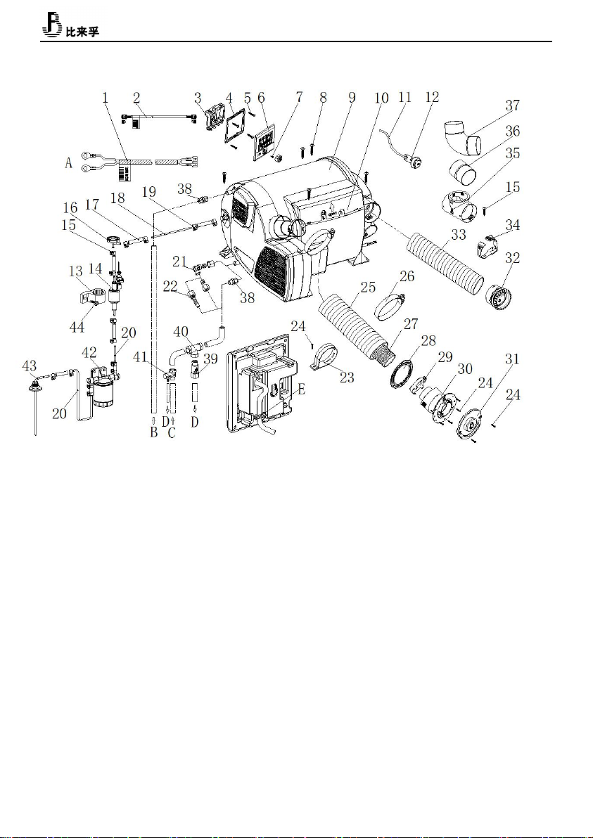
1-LCD switch 9- Combustion air inlet
2- External temperature sensor 10-Electronic control unit
3-Cold water inlet 11-Water container
4-Hot water outlet 12-Burner
5-Fuel connection 13-Heat exchanger
6-Warm air outlets 14-Power electronic
7-Circulated air intake 15-Heating elements
8-Exhaust discharge 16-Overheating switch
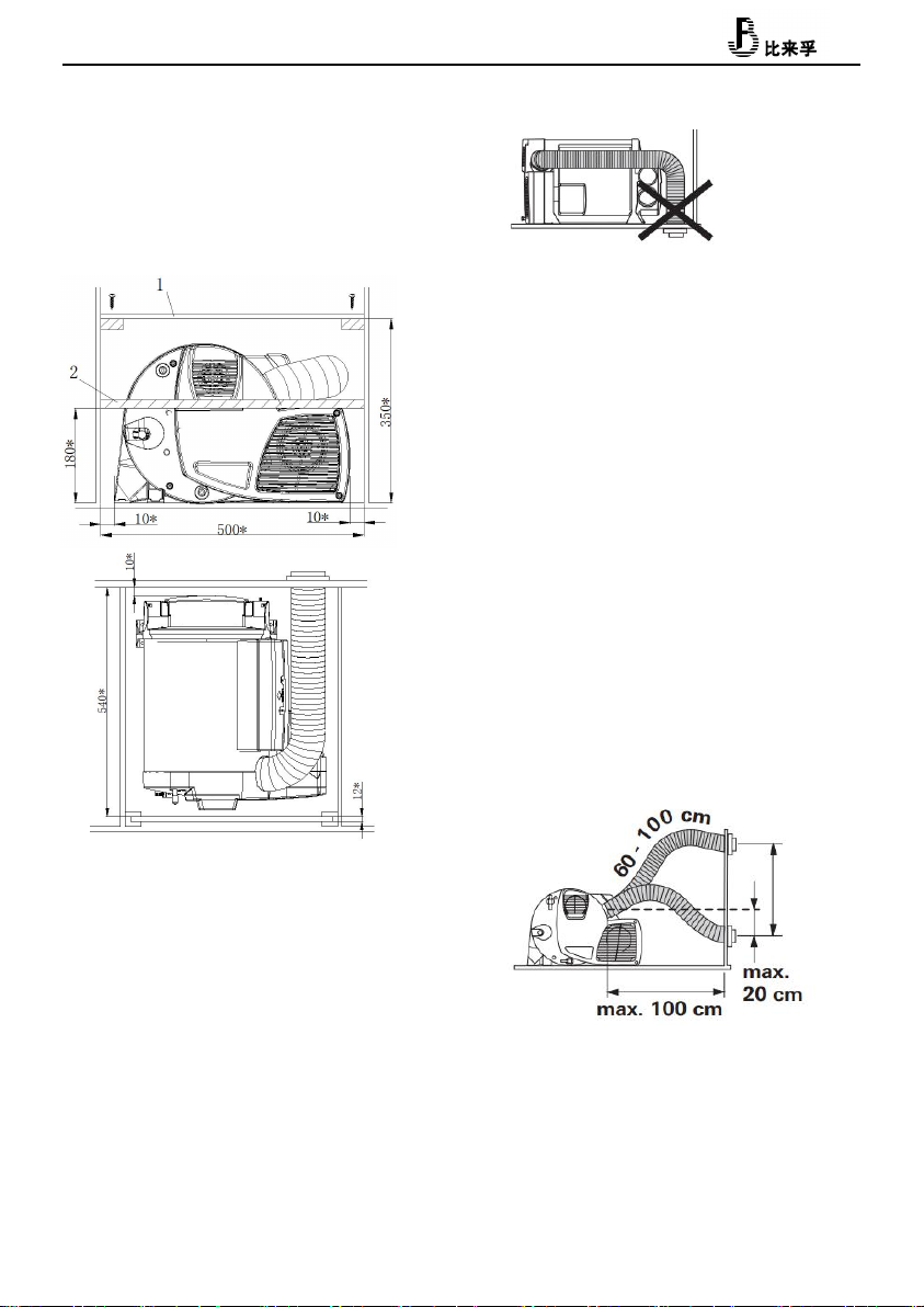
5. Heater installation
The typical installation of the heater is shown in
figure1.
★ Must be installed and repaired by professionals
authorized by the company!
The company does not bear any responsibility for the
following acts:
--Modified heater and accessories
--Modification of exhaust lines and accessories
--Do not follow the operating installation instructions
--Do not use our company's special accessories
Figure 1
1-LCD control switch
2-External temperature sensor
3-Recirculating air inlet (minimum
150cm2)
4-Heat pipe
5-Heat outlet
6-Smoking cowl
4
Heater installation Figure 3.
The heater installation location should be selected
from load-bearing floor, double floor or underfloor.
If there is no suitable floor, you can first make a
load bearing surface with plywood.
★The heater must be firmly fixed to the mounting
surface with
screws to prevent damage to the gas pipeline during
driving and cause danger.
Depending on the actual installation, may only
install three screws. Two die-cast aluminum fixing
screws are fixed then choose a plastic right angle
1_12V Power cord 2_ LCD switch Lead wire 3_ LCD switch back cover 4_ LCD switch bracket 5_ Self-tapping
screw M3*10 6_ LCD control switch 7_ Cross countersunk head flat tail self-tapping screw M3*6 8_ Self-tapping
screw ST5*25 9_ Heater 10_ Controller cover 11_ External temperature sensor lead wire 12_ External temperature
sensor 13_Fuelpump connector 14_Fuel pump 15_Fuel pipe clamp(φ9-11)16_Damper 17_Fuel pipe connector
18_6-Fuel pipe(trsparent,from heater to fuel pump)19_Fuel pipe clamp(φ8-10)20_ Fuel pipe(blue,from fuel
tank to fuel pump)21_φ10 Steel (water) pipe elbow transition fitting 22_ Hose(water) transition fitting
23_ Intake pipe mounting clamp 24_ Self-tapping screw ST3.5×25 25_ Air intake pipe 26_ German type clamp
27_ Exhaust pipe 28_ Sealing rubber spacer 29_(Exhaust pipe) clamp 30_ Intake and exhaust combine cowl31_
Intake and exhaust combine cover 32_ Air outlet 33_ Hot air ducting 34_ Ducting clamp 35_φ60T-pipe 36_
φ60connector 37_φ60 Elbow 38_ G1/2-φ10 Ferrule fitting 39 Frost valve 40_ G1/2 T pipe 41_ Reducing valve
42_Filter 43_Fuel suction pipe 44_Self tapping self drilling screw ST5*30
A_ Connect to 12V Battery B_ connect to water equipment C_ connect to system water tank
D_Flow out of the car E_ Hook,clamp LCD switcher cord
Figure 3
5
to fix it.
To ensure that the heater evenly distributes heat,
the heater should be installed in the center as much
as possible to ensure that the heating circuit is
equal long as possible.
No cover is allowed to add to the heater surface.
The size with* is the smallest size, leaving enough
space to connect accessories such as gas and water
pipes.
To prevent the danger from heater accidentally
loosening, the upper cover of the heater compartment
is screwed to the upper cover (Figure 4-1). Next to
the installation location it is necessary to install
a strong partition strip in front of the heater,
perpendicular to the direction of travel. Above the
floor height180mm can be attached to a septum
(minimum 30*50mm).
Heat sensitive objects and flammable objects should
be placed away from the heater.
★ The exhaust cowl must be on the side wall or
ceiling.
In the exhaust cowl installed area, there is no
ventilation window in the range of 300mm, and there
is no refueling port or tank respirator in the range
of 500mm.
The exhaust cowl is mounted below the window that is
close to or operable. A window switch should be
installed to ensure that the heater is turned off
automatically when the window is opened.
Air Inlet Hose Installation
The exhaust pipe is passing through the intake pipe.
The length of the intake and exhaust pipe is as shown
in Fig. 6, and the shortest is 60cm and the longest
is 100cm. The exhaust cowl is only allowed under the
exhaust outlet 20cm.
After the intake and exhaust pipes are pierced from
the through holes, they must be cut short, and the
exhaust pipes are slightly shorter than the intake
pipes. Avoid excessive expansion or tension on the
exhaust pipe.
Figture.4
Figture.5
Figure.6

6
The length of the intake and exhaust pipes is 100 cm
to 200 cm, as shown in Figure 7. The piping must be
arranged in the ascending direction.
The Exhaust Cowl (air inlet and outlet)
Installation
Select a flat mounting surface so that combustion air
can enter from all sides. Drill one hole of φ83. Seal
(Fig. 8-8), with the plane facing the exhaust cowl.
Wear the fixing clip before installing the exhaust
pipe (Figure 8-3). Pay attention to the installation
of the smoke cap upwards.
20mm at the end of the exhaust pipe should be
compressed, do not straighten. Insert the exhaust
pipe into the exhaust cowl interface(Figure 8-10),
as deep as possible. Try to fix the clips on the top,
tighten.
Place the air intake pipe (Figure 8-2) over the
exhaust cowl tooth (Figure 8-11). Set on the fixed
clip(Figure8-7), tighten.
Secure the exhaust cowl with 6 screws (Figure 8-9).
Use 2 screws to fix the exhaust cowl.
Fix the exhaust pipe on the side wall with mounting
clip.
Connect Air Inlet Pipe to The Heater
20mm at the end of the exhaust pipe should be
compressed, do not straighten.
Try to insert the exhaust pipe on exhaust port as deep
as possible。fix the clip on top, tighten.
Place the air intake pipe (Figure 9-3) over the air
inlet port (Figure 9-5). Set on the fixed clip
(Figure9-6), tighten.
Warm Air Intake
The warm air intake is drawn in by the heater. There
must be a total area between the room and the heater
not less than 150cm2 opening.
Figure.7
Figture.10
Figture.8
Figture.9
7
Ensure that the warm air intake is not contaminated
by the engine or heater exhaust, if necessary, with
structural isolation measures.
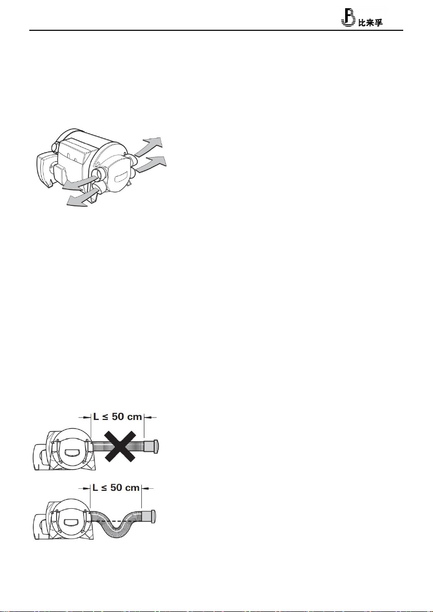
Warm Air Distribution
Most of the warm air is imported into the floor area
of the living compartment through the bellows.
The four air outlets on the heater are connected to
the φ65 bellows. Use only pressure piping that meets
the quality requirements of the Belief. Other pipes
that do not meet our quality standards (especially
wind resistance, pipe diameter and number of ripples)
shall not be used. If the warm air duct must withstand
a considerable amount of bending immediately after
the hot air outlet of the heater in a limited space,
we recommend using a 90° elbow (Figure 3-37). This
elbow can be connected to a diameter of 65mm hot air
duct.
In the case where the length of the pipe is less than
2 meters, the air outlet cannot be installed at a
height higher than the connection of the warm air
duct. When the pipe length is less than 50cm, the pipe
must be siphon between the connector and the outlet.
These measures prevent the undesirable heating
caused by (fairing effect) convection of the vehicle
during summer operation.
★The warm air pipe must be firmly inserted into the
connection port.
To get the best warm air distribution, Belief
recommends using 4 warm air outlets for the heater.
If only three warm air outlets are required, then a
lower warm air outlet must be selected to seal.
★ The cross section of the heater duct must not be
reduced due to pipe connections or the analogue.
In other words, no less than four warm air outlets
(figure 3_32) are opened. Make sure that more than
four warm air outlets are opened.
Fuel system connection
The fuel is extracted from the vehicle fuel tank or
supplied from the 10L special fuel tank. The fuel is
transferred and the fuel supply is adjusted through
the special fuel pump (provided by the
manufacturer).Fuel extraction from the vehicle
engine return system or downstream of the vehicle
internal delivery pump is not permitted. Please
install only the fuel hose and piping within the
delivery range.
The fuel shall meet national standards
GB19147-2013 diesel standard for vehicles
Winter fuel should meet the low temperature
requirements brand, do not allow the use of
biofuels.
Figure.12
Figture.11

8
Fuel line system
Installation of oil pipe
Only the flexible nylon pipe, which has good
light-resistance and thermal stability, supplied
with the heater can be used as the fuel pipe.
Allowable length of fuel line: the maximum length of
fuel line on the inlet side is 2 meters, and the
maximum length on the pressure side is 6 meters. As
shown in figure 13.
Safety Regulations for Fuel Pipe
Use a hose cutter or sharp cutter to cut the fuel hose
and pipeline into a certain length. The cut area
cannot be compressed and must be free of burrs. Fuel
pipelines must be firmly connected to prevent
vibration-induced damage or noise (the recommended
distance between connecting points is about 50 cm).
Fuel pipelines must be protected from mechanical
damage. The laying of fuel pipelines will not
adversely affect the stability of vehicle rotation
and engine operation. Protect fuel-carrying parts
from high temperatures that may affect operation
(use appropriate glass fiber lined aluminum thermal
protection hoses). Do not install or fix fuel lines
near the exhaust pipes of heaters or vehicle engines.
If the lines are crossed, keep enough distance from
the thermal components - provide a thermal radiation
shield if necessary. Pipe installation should be
able to prevent flying stones from hitting, and keep
away from heating parts of vehicles. Protective
devices should be installed when necessary.
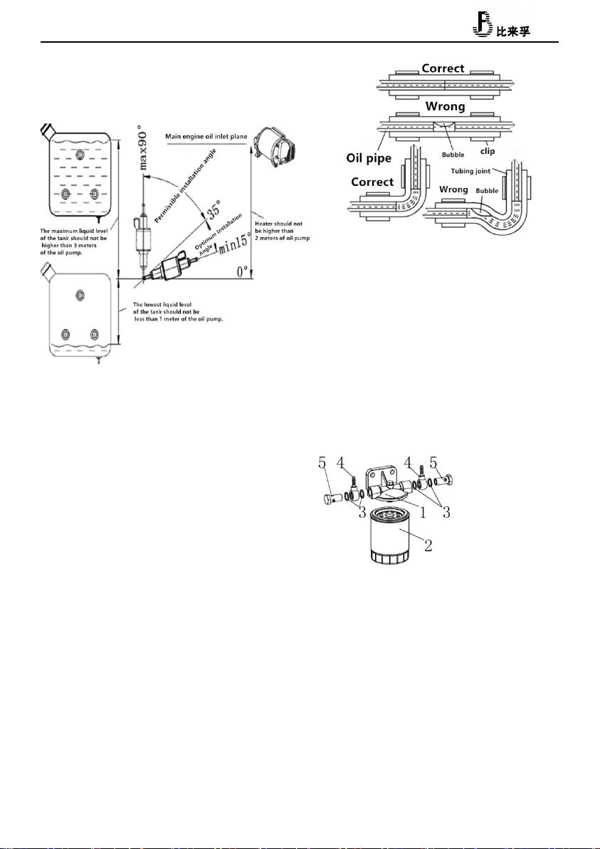
Installation of oil pump
The oil pump shall be fixed with a fixed jacket
(rubber) of the oil pump. The outlet of the oil pump
should be inclined upward, and its installation
angle should be selected in the range of 15- 35 as
shown in Figure 14. When conditions permit, the
tubing between the pump and the heater mainframe
should gradually rise. In order to prevent the oil
pump from being heated (the maximum operating
temperature is 40 C), do not install it near the
exhaust pipe.
The height difference between the fuel level and the
oil pump, and the height difference between the oil
pump and the main engine inlet, will generate
pressure (or suction) in the oil pipeline, so these
dimensions should meet the requirements of Figure 14
(negative pressure will occur in the closed tank,
when the minimum liquid level of the tank is required
to be no more than 0.4m).
Connection between heater and oil pump
The pipeline from the oil pump to the main engine
should go up as far as possible. Mark the appropriate
position on the floor of the vehicle for passage the
hole of the fuel pipeline and the oil pump connecting
9
the cable. Before drilling, pay attention to check
the hidden cable, fuel pipeline, frame section, etc.
The lower body protection device is then used to seal
the edges of the openings on the floor of the vehicle.
In order to prevent the cable between the tubing and
the oil pump from being cut, please add the lead-in
bushing or section edge protection material. The
tubing should be bundled at the appropriate place for
fixing, and the bundling distance is not more than
50 cm.
Connections between tubing and oil pump, main engine
and oil tank (oil intake nozzle) shall be made by
using tubing joints matched by this unit and using
oil. The pipe clip is clamped tightly. Prevent
bubbles from forming at the junction (Pic. 15).
Installation of Fuel Filter
Install the fuel filter before the oil inlet of the
oil pump. When installing, it should be noted that
the fuel filter must be vertical upward (to ensure
that impurities deposit downward). Fuel filter
replacement cycle for two years, tubing connection
head and clip must be replaced at the same time.
Installation of oil intake nozzle
(Pic17)
Firstly, the oil intake nozzle is fitted with O-ring,
and then it passes through the bottom hole
(self-processing) through the inside of the tank.
Put gaskets on the outside of the tank and tighten
them with nuts. The tightening torque is 6Nm+1Nm. The
O-ring must be clamped between the inner wall of the
Figure 15
Figure14
Figure16
1- Fuel filter aluminum base
2- Fuel filter
3- Sealing gasket
4- Articulated hose joint
5- Articulated bolt

10
Oil intake nozzle
O ring
Washer
Nut
Figure 17
Figure18
tank and the oil intake nozzle to ensure good sealing
between the oil intake nozzle and the oil tank.
(Accessories such as oil intake nozzles are attached
to the tank)
Installation of suction pipe(Pic.21)
Use when drawing fuel from the fuel tank of the
vehicle itself. When installing, attention should be
paid to the size of the installation hole on the tank
(or the cover of the tank) is 25 (+0.2), the edge is
neat and the surrounding is smooth, so as to ensure
good sealing between the suction pipe seat and the
tank. The distance between the bottom of the suction
pipe and the bottom of the tank should be 30-40 mm,
which can not only ensure the full absorption of fuel,
but also prevent the deposition of impurities at the
bottom of the tank from being inhaled.
The connection of water pipe
A pressure pump or submerged pump with a pressure of
2.8 bar can be used to supply water to the water tank.
If the water tank is connected to a centralized water
supply (rural or urban connection), or if a
high-pressure pump is used, a decompress or must be
used, which will prevent pressure above 2.8 bar.
★Before the relief valve is triggered, the
temperature rise and expansion of the water may cause
up to 4.5 bar of pressure (which may also occur with
the submerged pump). Water pipes connected to water
tanks and safety/drainage valves must be safe for
drinking water, pressure-resistant (up to 4.5 bar)
and hot water resistant up to 80°C. Antifreeze valve
(Pic3-39, Freeze-proof automatic water discharger),
A mechanical safety/drainage valve. When there is a
danger of frost, it will automatically drain water
from the tank through the drain.
Pressure relief valves must be installed(Pic3-41,
0.5MPa).If there is too much pressure in the system,
the pressure will automatically be released
intermittently through the relief valve.
Installation of External Temperature
Sensor
Install the car and measure the room temperature. The
installation position of the sensor is determined by
the manufacturer of the RV according to the specific
conditions of the vehicle. When choosing the
installation location, please note that the external
temperature sensor should not be subjected to direct
thermal radiation. In order to obtain the best room
temperature control, an external temperature sensor
is installed above the entrance door.
Suction pipes are only used in
metal tanks
Minimum distance 25 mm
Aperture

11
Make sure that the external temperature sensor is
always mounted on the vertical wall. It must be
surrounded by free-flowing air.
Drill a hole 10 mm in diameter. The single-wire
terminal passes through the opening from the back and
connects the end of the cable to the sensor with an
insulating plug (without observing polarity). Slide
into the external temperature sensor and connect the
two ends of the cable with two insulating connectors
to the heater electronic devices (if necessary,
extend the cable to a maximum length of 10 meters,
2 *0.5 mm 2 cable). The external temperature sensor
provided must always be connected, otherwise the
heater will switch to failure.
Install LCD switch
Gas heater must be operated by special liquid crystal
switch. See the relevant instructions for details.
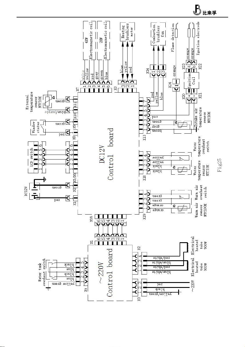
Electrical Connection
Lay wires to avoid scratches. If there are sharp
edges, such as metal panel threading, please use lead
bushing or edge protection accessories. Connector
cables shall not adhere to or touch metal surfaces,
exhaust pipes or hot air pipes.
The electrical connection socket is located below
the controller cover. The controller cover can be
removed by pressing and sliding along the arrow at
the same time. When removing or installing the
controller cover, make sure that the connecting
cable is not pulled out or squeezed.
1- DC12Vpositive electrode
2- DC12Vnegative electrode
3- Fuse
4- Window Switch
5- External temperature sensor
6- 7-control switch
When the window switch is not installed, the short
wiring cannot be removed. All cables connected to the
heater should be poked in a sagging direction. This
prevents condensate from slipping off the connector
cable and entering the heater.
Pic21
Figure19
Figure20

12
Connector cables and plugs must not be subjected to
force.(Pic19),Tie connector cables and fasten them
to the housing with straps to eliminate tension.
All cables must be firmly connected together. They
should not be loosened or disconnected by vibration,
resulting in fire hazards!
DC12V Power
The electric circuit, switch and control equipment
of the heater must be located in a position that will
not adversely affect its operation under normal
working conditions. The heater has reverse polarity
protection. If the controller is not properly
polarized, the LED indicator will not work.
In order to provide the best power supply, the heater
must be connected to the on-board power supply (or
battery) protected by fuse (10A) with a 2 x 2.5 mm
2 cable (2 x 4 mm 2 for a length exceeding 6 m). If
necessary, the voltage drop of the power supply line
must be considered. Connect the negative pole line
to the main grounding. If the heater is directly
connected to the battery, the positive and negative
lines must be protected. Do not connect other
power-consuming equipment.
Electrical connection of oil pump
Make sure the plug is firmly connected.
Figure22
Pic23
Pic24
13
14
6. Operating precautions
Heaters are not allowed to operate during refueling
or in enclosed spaces (enclosed parking lots, repair
shops or ferry compartments). Check regularly
whether the intake and exhaust pipes are in good
condition and the fixing is reliable, especially
after a trip. Also check the fixing of intake and
exhaust pipes and smoke caps.
When black smoke is found, the company's authorized
professionals are requested to carry out the
inspection. Ensure that the exhaust pipe and intake
pipe at the smoke exhaust cap are free from blockages
such as snow, ice and leaves. Warm air outlet and
circulating air inlet are unobstructed to avoid
overheating of heater. In the case of overheating,
the overheating switch will immediately cut off the
fuel supply.
If the fuel heater wants to meet the heating needs
in driving, it should install safety shut-off
device.
★If there is no safety shut-off device, the heater
must be turned off before driving.
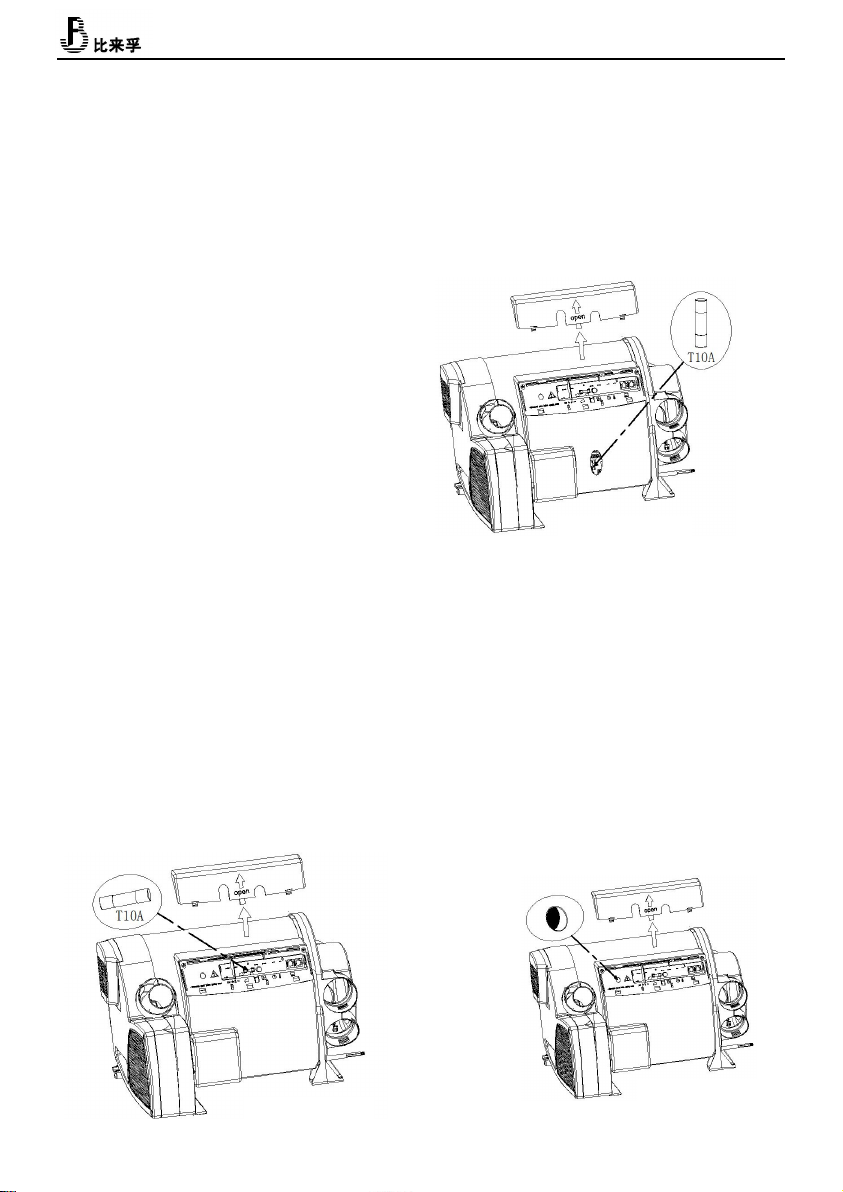
12V Fuse
Replacement with exactly the same fuse T20A is
allowed only.
~220V Fuse
★Fuses and wiring harnesses must be replaced by
professionals authorized by the Company.
★ All power supply must be disconnected before
opening the control housing.
Fuse Specification: T10A Slow Fuse
~220V Overheat protection
The municipal electric heating function has a
mechanical overheating protection switch. If the 12V
power supply is interrupted during or after the
heating process, the excess heat of the heater will
trigger the overheating protection switch.
When the temperature of the water tank decreases,
disconnect the power supply from 220V, remove the
cover of the controller, and reset the overheat
protection switch by pressing the reset button by
hand.
Figure26
Figure27
Figure28

15
7. Operational instructions
Please read the instructions carefully before
operation.
Start-up heater
Use special liquid crystal switch to operate.
Fuel oil, electricity, mixing mode, heating water
tank or unheated water tank for main engine heating
are set according to need.
Check the power supply capacity of RV camps, and
choose the operation mode of 900W (3.9A) or 1800W
(7.8A) accordingly. -- Check whether the smoke
exhaust cap is unobstructed
-- Open Liquefied Gas Tank Switch Valve
-- The tank is full of water when needed
Filling of water
Check whether the relief valve/drain valve is
closed.
——Turn on the pump power supply (main gate or pump
switch)
——Open the hot water tap in the kitchen or bathroom
and keep the valve open until the air in the container
is discharged and the water is continuously
discharged.
——In the absence of water heater heating, if only
the cold water system is in operation, the water
heater will also be full of water. To avoid frost
damage, the water heater must be drained through a
safety/drainage valve, even if it is not running.
——In the case of frost, the frozen residual water
can prevent filling. The water heater can thaw (no
more than 2 minutes) if it is turned on for a while.
The ice can be thawed through the inside of the
heater.
——If the heater is connected to the central water
supply system (rural or urban water supply system),
a pressure reducer must be used to prevent pressure
exceeding 2.8 bar (0.28 MPa).
-- Open the circulating pump
-- Open the hot tap in the kitchen and bathroom until
the air is exhausted and the water tank is filled,
and the water is not interrupted.
Turn off the heater
-- Use special liquid crystal switch to operate.
-- After the heater is closed, the
combustion-supporting fan and heating fan will
continue to work for several minutes according to the
temperature of the furnace body.
In case of freezing danger, it is necessary to ensure
that the water tank is emptied.
-- Close the circulating pump
-- Turn on the hot tap in the kitchen and bathroom
Heater drainage
——If the RV is not used during the frost. The heater
must drain the water.
——Turn off the power supply (main power supply or
pump switch) of the pump unit.
——Turn on the hot tap in the kitchen and bathroom.
— — In order to check the effluent, the
safety/drainage valve (user-fitted, for manual
emptying of the water tank) is installed. The
anti-freeze valve cannot ensure that the water tank
is completely emptied. Place a suitable container
under the drain tank.
——Open the safety/drainage valve.
——The heater will be discharged directly to the
outside through the safety/drainage valve. Check
whether all water in the heater has been discharged
into the container through the safety/drainage valve.

16
Claims for damage caused by frost shall not be filed
during the warranty period.
★The 10L bucket can be used for water inspection
to ensure that the water tank is empty.
The valve of liquefied gas tank must be closed before
heater is not used for a long time or running.
Maintenance/repair/cleaning
-- The device can only be repaired and cleaned by
experts.
-- Maintenance, repair and cleaning cannot be done
by children.
-- With new equipment, or the equipment has not been
used for some time, thoroughly flush all hot/cold
water hoses before use.
8. Failure
8.1 General Failure Handling
8.1.1 During the use of the heater, it may appear that
it cannot start normally or turn off it after
starting and is in the fault lock state. At this time,
the heater can be turned off for more than 5S and
restart.
8.1.2 The heater may cause circuit failure due to the
following reasons: the connector is rusted, the poor
contact, the plug is incorrect, the wire or fuse is
rusted, the battery pile is rusted, etc.
Pay attention to inspection, maintenance and prevent
these phenomena from occurring during use.
8.1.3 When the following conditions occur, it can be
handled and eliminated by the user:
●The heater does not start after the power is turned on and
the LCD switch screen does not light. The reason is that the
fuse is open, or the wiring is wrong. In addition, check
whether the plug on the LED switch lead wire is properly
connected to the host.
8.2 Fault Lock Status
8.2.1 The fault generated by the heater is indicated by
the fault code on the LED switch.
8.2.2 The faults can be eliminated according to the methods
Listed in Table 2.

17
Fault Lock Status Debug Method
Fault
Code
Fault Name
Fault Debu Method
10
Overvoltage fault
a. Check vehicle power supply system
11
Under voltage fault
a. Check vehicle power supply system
21
Warm air outlet temperature sensor
disconnection
a. Check if the sensor is in good condition
22
Warm air outlet temperature sensor short
circuit
a. Check if the sensor is in good condition
23
Water temperature sensor disconnection
a. Check if the sensor is in good condition
24
Water temperature sensor short circuit
a. Check if the sensor is in good condition
25
External temperature sensor disconnection
a. Check if the sensor is in good condition
26
External temperature sensor short circuit
a. Check if the sensor is in good condition
27
Combustion support temperature sensor
disconnection
a. Check if the sensor is in good condition
28
Combustion support temperature sensor
short circuit
a. Check if the sensor is in good condition
31
Combustion failure
a. Check gas supply system
b. Check whether combustion inlet and outlet are
blocked
c. Check the Ignition coil, ignition
electrode, flame sensor

18
Fault Lock Status Debug Method
Fault
Code
Fault Name
Fault Debug Method
32
Combustion failure
a. Check gas supply system
b. Check whether combustion inlet and outlet are blocked
c. Check the flame sensor
33
Flame sensor fault
a. Check the flame sensor lead wire
b. Check the flame sensor
41
Warm air outlet overheats
a. Check whether air outlet is blocked
42
Warm air overheats switch protection
a. Check whether air outlet is blocked
b. Check warm air overheat switch
43
Water overheat
a. Check whether water depletion in the tank
b. Check if the sensor is in good condition
c. Check whether air outlet is blocked
44
Warm air overheats switch protection.
a. Check whether air outlet is blocked
b. Check warm air overheat switch
45
Overheating fault
a. Check whether air outlet is blocked
b. Check water temperature sensor
c. Check warm air sensor
51
Communication fault
a. Check interconnecting cable
61
Oil Pump Break
a.Check whether the oil pump lead is damaged or not b.
Check whether the connection of oil pump leads is reliable
C. refurbishment oil pump
d. Replacement of motherboard
62
Short circuit of oil pump
a. Check whether the oil pump lead is damaged
b. Check whether the connection of oil pump leads is reliable
C refurbishment oil pump
d. Replacement of motherboard
63
Circuit Breaking of Electric Plug
A Check the power supply voltage
B Check the resistance of the plug at room temperature (0.2/12V)
C Cleaning up Carbon Accumulation in Electric Plug D
Replacement of motherboard
Table of contents
Other Belief Heater manuals


Popular Heater manuals by other brands


Kambrook
Kambrook KFH340 Instruction booklet

VTsistema
VTsistema EHC Series manual

NARVI Oy Finland
NARVI Oy Finland KOTA Kuru 14 installation, user and maintenance instructions

bewello
bewello BW2101 user manual

BONAIRE
BONAIRE Pyrox Heritage Operator's manual

Beyerdynamic
Beyerdynamic SIR 802 operating instructions