Mestek R(B User manual

Form 43471040
Oct 2013
INSTALLATION AND OPERATION INSTRUCTIONS
OWNER / INSTALLER: For your afety thi manual mu t be carefully and thoroughly read and
under tood before in talling, operating or ervicing thi heater.
RESIDENTIAL RADIANT GARAGE TUBE HEATER
Single and Two Stage Pull Through Sy tem (Negative Pre ure)
Model :
R (B,S,M) G 02
22
25 – (N1/L1/N2/L2)
R (B,S,M) G 035 – (N1/L1/N2/L2)
R (B,S,M) G 045 – (N1/L1/N2/L2)
!INSTALLER:
Thi manual i the property of the owner. Plea e pre ent thi manual to the
owner when you leave the job ite.
▲WARNING: Improper in tallation, adju tment, alteration, ervice, or maintenance can
cau e property damage, injury or death. Read the in tallation, operation and maintenance
in truction thoroughly before in talling or ervicing thi equipment.
IF YOU SMELL GAS: FOR YOUR SAFETY
FOR YOUR SAFETYFOR YOUR SAFETY
FOR YOUR SAFETY
!
!!
!
DO NOT
DO NOTDO NOT
DO NOT try to light any appliance.
!
!!
!DO NOT
DO NOTDO NOT
DO NOT touch any electrical witch; DO NOT
DO NOTDO NOT
DO NOT u e any
telephone in your building.
!
!!
!IMMEDIATELY
IMMEDIATELYIMMEDIATELY
IMMEDIATELY call your ga upplier from a neighbor'
telephone. Follow the ga upplier' in truction . If you
cannot reach your ga upplier, call the fire department.
DO NOT
DO NOT DO NOT
DO NOT tore or u e ga oline or other
tore or u e ga oline or other tore or u e ga oline or other
tore or u e ga oline or other
flammable vapor and liquid in the vicinity of
flammable vapor and liquid in the vicinity of flammable vapor and liquid in the vicinity of
flammable vapor and liquid in the vicinity of
thi or any other appliance.
thi or any other appliance.thi or any other appliance.
thi or any other appliance.
!IMPORTANT:
!IMPORTANT:!IMPORTANT:
!IMPORTANT:
SAVE THIS MANUAL FOR F
SAVE THIS MANUAL FOR FSAVE THIS MANUAL FOR F
SAVE THIS MANUAL FOR FUTURE REFERENCE.
UTURE REFERENCE.UTURE REFERENCE.
UTURE REFERENCE.
Me tek, Inc.
Me tek, Inc.Me tek, Inc.
Me tek, Inc.
260 North Elm St. • We tfield, MA 01085
Telephone (413) 568-9571 • Fax (413) 562-8437 • www.me tek.com

Form 43471040
Oct 2013 -1-
TABLE OF CONTENTS
SECTION DESCRIPTION PAGE
1.0) Safety ................................................................................................................................................... 2
2.0) In taller Re pon ibility ...................................................................................................................... 2
3.0) General Information........................................................................................................................... 2
4.0) Minimum Clearance to Combu tible ........................................................................................... 4
5.0) Specification ...................................................................................................................................... 5
6.0) Packing Li t ......................................................................................................................................... 5
6.1) Acce ory Package .......................................................................................................................... 7
7.0) Dimen ion ......................................................................................................................................... 8
8.0) Heater A embly Overview ............................................................................................................... 9
9.0) Typical Su pen ion Method .......................................................................................................... 10
10.0) Heater A embly .............................................................................................................................. 11
11.0) Ga Connection and Regulation ................................................................................................. 14
12.0) In truction for Pre ure Te t Gauge Connection ....................................................................... 16
13.0) Electrical and Thermo tat Connection ........................................................................................ 17
14.0) Venting ............................................................................................................................................... 25
15.0) Air for Combu tion ........................................................................................................................... 30
15.1) Direct Out ide Air for Combu tion ................................................................................................. 30
16.0) Lighting and Shutdown In truction .............................................................................................. 32
17.0) Sequence of Operation .................................................................................................................... 32
18.0) Control Component Location .......................................................................................................... 33
19.0) Cleaning and Annual Maintenance ............................................................................................... 34
20.0) Trouble hooting Guide..................................................................................................................... 35
21.0) Replacing Part ................................................................................................................................ 38
21.1) Removal of Spark Electrode ........................................................................................................... 38
21.2) Removing Main Burner and Ga Valve ......................................................................................... 39
21.3) Air Switch Pre ure Check .............................................................................................................. 39
21.4) Ignition Sy tem Check ................................................................................................................... 40
21.5) Motor and Blower Wheel Check ..................................................................................................... 41
22.0) In tallation Data ............................................................................................................................... 41
23.0) Replacement Part Guide ............................................................................................................... 42
24.0) Warning Card .................................................................................................................................. 46
Thi heater complie with ANSI Z83.20 (current tandard) and CSA 2.34. Copie of the National Fuel Ga Code (ANSI
Z223.1-late t edition) are available from the CSA at 8501 Ea t Plea ant Valley Road, Cleveland, Ohio 44131 or 55 Scar dale
Road, Don Mill , Ontario M3B 2R3. All NFPA code are available from the National Fire Protection A ociation, Batterymarch
Park, Quincy, Ma achu ett 02269.
For in tallation with mounting height le than 10 feet, in tall the
heater at the highe t po ible height for the be t radiant energy
di tribution.

Form 43471040
-2- Oct 2013
1.0) SAFETY
Thi heater i a elf-contained infrared radiant tube heater. Safety information required during in tallation and
operation of thi heater i provided in thi manual and the label on the product. The in tallation, ervice and
maintenance of thi heater mu t be performed by a contractor qualified in the in tallation and ervice of ga
fired heating equipment.
All per onnel in contact with the heater mu t read and under tand all afety information, in truction and label
before operation. The following ymbol will be u ed in thi manual to indicate important afety information.
SAFETY
SAFETYSAFETY
SAFETY
REQUIREMENTS
REQUIREMENTSREQUIREMENTS
REQUIREMENTS
•
••
•The heater area mu t be kept clear and free from combu tible material , ga oline and other flammable
vapor and liquid .
•
••
•Thi heater i de igned for u e with one type of ga (LPG or Natural). Make ure that the type of ga to be
upplied to thi heater matche that hown on the heater rating plate.
•
••
•DO NOT
DO NOTDO NOT
DO NOT in tall thi heater directly onto an LPG container or propane cylinder without direction from your
propane company. LPG container (propane cylinder ) mu t not be tored indoor or in the vicinity of any
ga -burning appliance.
•
••
•Children and adult hould be alerted to the hazard of high urface temperature and hould tay away to
avoid burn or clothing ignition.
•
••
•Clothing or other flammable material hould not be hung from the heater or placed on or near the heater.
•
••
•Young children hould be carefully upervi ed when they are in the ame pace a the heater.
•
••
•NEVER
NEVERNEVER
NEVER attempt to ervice the heater while it i plugged in, operating or hot. Any guard or other protective
device removed for ervicing a heater mu t be replaced prior to operating the heater.
Warning
WarningWarning
Warning
in truction mu t be followed to prevent or avoid hazard which
may cau e eriou injury, property damage or death.
Caution
CautionCaution
Caution
in truction mu t be followed to prevent incorrect operati
on or
in tallation of
the heater which may cau e minor injury or property
damage.
2.0) INSTALLER RESPONSIBILITY
The in taller i re pon ible for the following:
•
••
•The heater and venting, a well a electrical and ga upplie mu t be in talled in accordance with the e
in tallation in truction and any applicable code and regulation .
•
••
•Every heater hall be located with re pect to building con truction and other equipment o a to permit
acce to the heater.
•
••
•Each in taller mu t follow the clearance to combu tible material for the heater .
•
••
•In tall the heater o that the upport and hanger are correctly paced in accordance with the e
in truction . The heater mu t be upported by material having a working load limit of at lea t 115lb .
•
••
•Supply the owner with a copy of the e In tallation and Operation In truction .
•
••
•Where unvented heater are u ed, gravity or mechanical mean hall be provided to upply and exhau t at
lea t 4 CFM per 1,000 Btu/hr input of in talled heater .
•
••
•Never u e the heater a a upport for a ladder or other acce equipment. Do not hang anything from the
heater.
•
••
•Supply all in tallation material nece ary that are not included with the heater.
•
••
•Check the nameplate to make ure that the burner i correct for the ga type in the building and the
in tallation altitude.
3.0) GENERAL INFORMATION
Thi heater i a elf-contained infrared radiant tube heater for u e in location where flammable ga e or vapor
are not generally pre ent (a defined by OSHA acceptable limit ) and i intended for pace heating of garage ,
ve tibule and entry way , work hop , enclo ed patio , golf practice range and mo t indu trial and commercial
application . DO NOT
DO NOTDO NOT
DO NOT in tall thi heater in re idential bedroom or bathroom , mobile home or recreational
vehicle .

Form 43471040
Oct 2013 -3-
INSTALLATION RE
INSTALLATION REINSTALLATION RE
INSTALLATION REQUIREMENTS
QUIREMENTSQUIREMENTS
QUIREMENTS
The in tallation mu t conform to local building code or in the ab ence of local code , with the National Fuel Ga
Code ANSI Z223.1/NFPA54 or the Natural Ga and Propane In tallation Code CSA B149.1. Heater hall be
in talled by a licen ed contractor or licen ed in taller. Clearance to combu tible a outlined in thi manual
hould alway be ob erved. In area u ed for torage of combu tible material where they may be tacked
below the heater, NFPA54 require that the in taller mu t po t ign that will “ pecify the maximum permi ible
tacking height to maintain the required clearance from the heater to combu tible .”
Every heater hall be located with re pect to building con truction and other equipment o a to permit acce
to the heater. Each in taller hall u e quality in tallation practice when locating the heater and mu t give
con ideration to clearance to combu tible material , vehicle parked below, light , overhead door , torage
area with tacked material , prinkler head , ga and electrical line and any other po ible ob truction or
hazard . Con ideration al o mu t be given to ervice acce ibility.
The heater, when in talled in aircraft hangar and public garage , mu t be in talled in accordance with
ANSI/NFPA 409-late t edition (Standard for Aircraft Hangar ), ANSI/NFPA 88a-late t edition (Standard for
Parking Structure ), and ANSI/NFPA 88b-late t edition (Standard for Repair Garage ) with the following
clearance :
a. At lea t 10 feet above the upper urface of wing or engine enclo ure of the highe t aircraft that may be
hou ed in the hangar and at lea t 8 feet above the floor in hop , office , and other ection of hangar
communicating with aircraft torage or ervice area .
b. At lea t 8 feet above the floor in public garage . ▲
▲▲
▲WARNING:
WARNING:WARNING:
WARNING: Minimum clearance marked on the heater
mu t be maintained from vehicle parked below the heater.
(FOR CANADA ONLY)
a.
In tallation of thi appliance i to be in accordance with late t edition of
CSA
B149.1 (
Natural Ga and
Propane In tallation Code).
b. For in tallation in public garage or aircraft hangar , the minimum clearance from the bottom of the
infrared heater to the upper urface of the highe t aircraft or vehicle hall be 50 percent greater than the
certified minimum clearance, but the clearance hall not be le than 8 feet.
Although the e heater may be u ed in many application other than pace heating (e.g., proce heating),
Me tek will not recognize the warranty for any u e other than pace heating.
For indoor in tallation only. No
For indoor in tallation only. NoFor indoor in tallation only. No
For indoor in tallation only. Not for u e in re idential dwelling .
t for u e in re idential dwelling .t for u e in re idential dwelling .
t for u e in re idential dwelling .
Thi heater i for Indoor In tallation and Covered Patio In tallation only and can be u ed in either Vented or
Unvented mode. The term Unvented actually mean Indirect Vented. While the product of combu tion are
expelled into the building, national code require ventilation in the building to dilute the e product of
combu tion. Thi ventilation may be provided by gravity or mechanical mean .
Thi heater i not an explo ion proof heater.
Thi heater i not an explo ion proof heater.Thi heater i not an explo ion proof heater.
Thi heater i not an explo ion proof heater. Where the po ibility of expo ure to volatile and low fla h point
material exi t , it could re ult in property damage or death. Thi heater mu t not be in talled in a pray booth
where the heater can operate during the praying proce . Con ult your local fire mar hal or in urance company.
High Altitude:
High Altitude:High Altitude:
High Altitude:
Appliance are upplied a tandard for altitude of O to 2,000 feet (0-610 m). High-altitude rating are obtained
by a change in the orifice ize. When ordered for high altitude in tallation , burner are upplied by the factory
ready for high altitude in tallation. Check the nameplate for altitude before proceeding with the in tallation. In
Canada the adju tment for altitude i made in accordance with Standard CGA 2.17, Ga -Fired Appliance for U e
at High Altitude .
Form 43471040
-4- Oct 2013
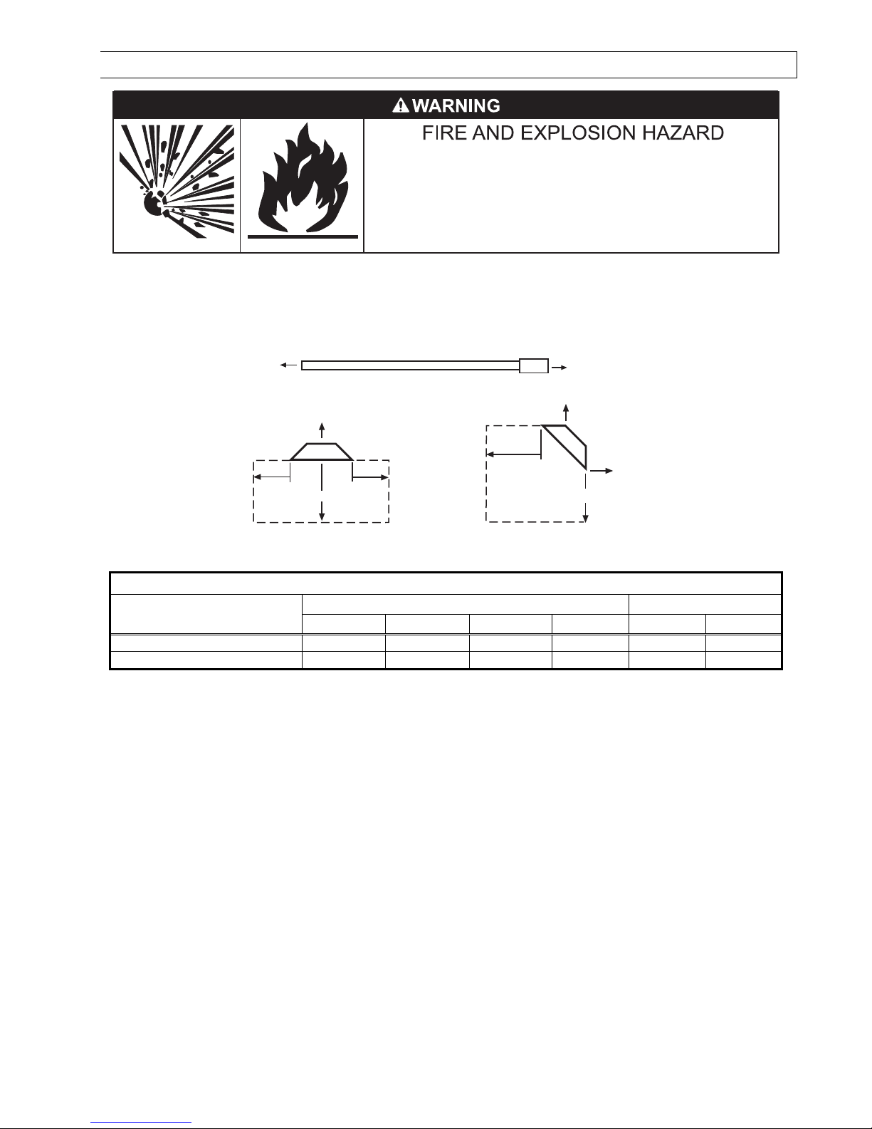
4.0) MINIMUM CLEARANCES TO COMBUSTIBLES
Failure to do so may result in death, serious injury or
property damage.
Combustible material must be located outside the
clearance dimensions listed.
Minimum clearance to combu tible hall be mea ured from the outer urface a hown in the following
diagram. For reduced clearance below the heater, u e the Deflector Kit (Part No. 43504010), de cribed in
Section 6.1), and maintain the minimum clearance pecified in the note below. Follow the in truction
packaged with the kit for in tallation. In tall the warning card (ordered eparately) and complete the blank
pace u ing the clearance from combu tible table below. See Section 24 for a printed copy of the warning
card.
End End
Ceiling
Below
Front Rear
45° Angle (Maximum)
* Ceiling
Below
Side Side
Horizontal
MINIMUM CLEARANCES TO COMBUSTIBLES
MINIMUM CLEARANCES TO COMBUSTIBLESMINIMUM CLEARANCES TO COMBUSTIBLES
MINIMUM CLEARANCES TO COMBUSTIBLES
Model No.
Model No.Model No.
Model No.
Mounted Horizontally
Mounted HorizontallyMounted Horizontally
Mounted Horizontally
Angle Mounted at 45º
Angle Mounted at 45ºAngle Mounted at 45º
Angle Mounted at 45º
Side
SideSide
Side
Ceiling
CeilingCeiling
Ceiling1
11
1
Below
BelowBelow
Below2
22
2
End
EndEnd
End
45º Front
45º Front45º Front
45º Front
45º Rear
45º Rear45º Rear
45º Rear
R (B,S,M) G
0
25
8
”
4
”
4
1
”
*
8
”
30
”
4
”
R (B,
S,M) G
0
35,
0
45
12
”
4
”
57
”
**
8
”
4
0
”
4
”
1 The clearance i 12” when in talled in an UNVENTED
UNVENTEDUNVENTED
UNVENTED configuration in indu trial and commercial in tallation .
2 IN CANADA
IN CANADAIN CANADA
IN CANADA, clearance below the heater are:
R (B,S,M) G 025: 36” (27” with deflector);
R (B,S,M) G 035, 045: 48” (36” with deflector)
* The clearance i 33” with deflector.
** The clearance i 42” with deflector / 30” ide clearance with deflector.
▲WARNING:
▲WARNING:▲WARNING:
▲WARNING:
Certain material or object , when tored under the heater, will be ubjected to radiant heat and
Certain material or object , when tored under the heater, will be ubjected to radiant heat and Certain material or object , when tored under the heater, will be ubjected to radiant heat and
Certain material or object , when tored under the heater, will be ubjected to radiant heat and
could be eriou ly damaged.
could be eriou ly damaged.could be eriou ly damaged.
could be eriou ly damaged.
Ob erve the Minimum Clearance to Combu tible li ted in the manual and on the
Ob erve the Minimum Clearance to Combu tible li ted in the manual and on the Ob erve the Minimum Clearance to Combu tible li ted in the manual and on the
Ob erve the Minimum Clearance to Combu tible li ted in the manual and on the
heater at all time .
heater at all time .heater at all time .
heater at all time .
NOTE:
NOTE:NOTE:
NOTE:
1.
1. 1.
1. The cleara
The clearaThe cleara
The clearance pecified above mu t be maintained to combu tible and other material that may be
nce pecified above mu t be maintained to combu tible and other material that may be nce pecified above mu t be maintained to combu tible and other material that may be
nce pecified above mu t be maintained to combu tible and other material that may be
damaged by temperature 90ºF above ambient temperature.
damaged by temperature 90ºF above ambient temperature.damaged by temperature 90ºF above ambient temperature.
damaged by temperature 90ºF above ambient temperature.
Clearance to combu tible are po ted on the
Clearance to combu tible are po ted on the Clearance to combu tible are po ted on the
Clearance to combu tible are po ted on the
control box.
control box.control box.
control box.
In area u ed for torage of combu tible material whe
In area u ed for torage of combu tible material wheIn area u ed for torage of combu tible material whe
In area u ed for torage of combu tible material where they may be tacked below the heater,
re they may be tacked below the heater, re they may be tacked below the heater,
re they may be tacked below the heater,
NFPA54 require that the in taller mu t po t ign that will “ pecify the maximum permi ible tacking height
NFPA54 require that the in taller mu t po t ign that will “ pecify the maximum permi ible tacking height NFPA54 require that the in taller mu t po t ign that will “ pecify the maximum permi ible tacking height
NFPA54 require that the in taller mu t po t ign that will “ pecify the maximum permi ible tacking height
to maintain the required clearance from the heater to combu tible .”
to maintain the required clearance from the heater to combu tible .”to maintain the required clearance from the heater to combu tible .”
to maintain the required clearance from the heater to combu tible .”
Me tek
Me tekMe tek
Me tek
recommend po ting the e ig
recommend po ting the e igrecommend po ting the e ig
recommend po ting the e ign
n n
n
adjacent to the heater thermo tat or other uitable location that will provide enhanced vi ibility.
adjacent to the heater thermo tat or other uitable location that will provide enhanced vi ibility.adjacent to the heater thermo tat or other uitable location that will provide enhanced vi ibility.
adjacent to the heater thermo tat or other uitable location that will provide enhanced vi ibility.
2. The tated clearance to combu tible repre ent a urface temperature of 90
2. The tated clearance to combu tible repre ent a urface temperature of 902. The tated clearance to combu tible repre ent a urface temperature of 90
2. The tated clearance to combu tible repre ent a urface temperature of 90
ºF
ºFºF
ºF
(32
(32(32
(32
ºC) above room
ºC) above room ºC) above room
ºC) above room
temperature. Building material with a low heat tole
temperature. Building material with a low heat toletemperature. Building material with a low heat tole
temperature. Building material with a low heat tolerance ( uch a pla tic , vinyle iding, canva , tri
rance ( uch a pla tic , vinyle iding, canva , trirance ( uch a pla tic , vinyle iding, canva , tri
rance ( uch a pla tic , vinyle iding, canva , tri-
--
-ply, etc.)
ply, etc.) ply, etc.)
ply, etc.)
may be ubject to degradation at lower temperature . It i the in taller’ re pon ibility to a ure that adjacent
may be ubject to degradation at lower temperature . It i the in taller’ re pon ibility to a ure that adjacent may be ubject to degradation at lower temperature . It i the in taller’ re pon ibility to a ure that adjacent
may be ubject to degradation at lower temperature . It i the in taller’ re pon ibility to a ure that adjacent
material are protected from degradation.
material are protected from degradation.material are protected from degradation.
material are protected from degradation.

Form 43471040
Oct 2013 -5-
5.0) SPECIFICATIONS
Model
Model Model
Model
Serie
Serie Serie
Serie No.
No.No.
No.
R (
R (R (
R (B,S,M)G
B,S,M)GB,S,M)G
B,S,M)G
Btu/hr
Btu/hrBtu/hr
Btu/hr
Input
InputInput
Input
Heat
Heat Heat
Heat
Exchanger
Exchanger Exchanger
Exchanger
Length
LengthLength
Length
Total
Total Total
Total
Heater
Heater Heater
Heater
Length
LengthLength
Length
Flue Re trictor
Flue Re trictorFlue Re trictor
Flue Re trictor
Plate
PlatePlate
Plate
I.D. &
I.D. & I.D. &
I.D. & Part #
Part #Part #
Part #
Orifice Size
Orifice SizeOrifice Size
Orifice Size
Minimum *
Minimum *Minimum *
Minimum *
Mounting Height
Mounting HeightMounting Height
Mounting Height
Natural Ga
Natural GaNatural Ga
Natural Ga
Propane Ga
Propane GaPropane Ga
Propane Ga
@
@@
@
Horizontal
HorizontalHorizontal
Horizontal
@
@@
@
45º Angle
45º Angle45º Angle
45º Angle
025
2
5
,000
16’ 9’-3”
7/8”
#4
2741120
#4
2
(0.
0
94
)
#52
(0.0
64
)
8’
8’
0
3
5
35
,000
1”
#4
2741041
#35
(0.1
10
)
1.75mm
(0.0
69
)
8’
8’
0
45
45
,000
1
-
1/8”
#4
2741031
1/8”
(0.1
25
)
5/64”
(0.0
78
)
8’
8’
* MOUNT HEATERS AS HIGH AS POSSIBLE. Minimum are hown a a guideline for human comfort and uniform
energy di tribution for complete building heating application . Con ult your Me tek repre entative for the
particular of your in tallation requirement .
Type
TypeType
Type
Ga
GaGa
Ga
Ga Pipe
Ga PipeGa Pipe
Ga Pipe
Connection
Connection Connection
Connection
Tube
TubeTube
Tube
Diameter
DiameterDiameter
Diameter
Flue
FlueFlue
Flue
Connection
ConnectionConnection
Connection
Fre h Air
Fre h Air Fre h Air
Fre h Air
Connection
ConnectionConnection
Connection
Electrical
ElectricalElectrical
Electrical
Supply
SupplySupply
Supply
Current
CurrentCurrent
Current
Rating
RatingRating
Rating
Natural
or Propane
½” MPT
(Male) 3” 4” Round 4” Round
120 Volt,
60Hz,
1 Pha e 2.6 Amp
Fu e
Fu eFu e
Fu e
Rating:
Rating:Rating:
Rating:
Ignition Sy tem (direct park):
Ignition Sy tem (direct park):Ignition Sy tem (direct park):
Ignition Sy tem (direct park):
Spark Module: 2
Amp 250V
(for 24V Circuit) 30 econd pre-purge period
6.0) PACKING LIST
A.
A.A.
A. Control/Draft Inducer
Control/Draft InducerControl/Draft Inducer
Control/Draft Inducer
Package
PackagePackage
Package
Part De cription
Part De cription Part De cription
Part De cription
QTY
QTYQTY
QTY
Control Box A embly
................................
................................
................................
..............................
1
Draft Inducer A embly (with 4” Starting Collar
#40504020
)
................................
.........................
1
Flue Re trictor Plate (refer to
5.0)
for I.D. & part number)
................................
................................
.
1
15” Pla tic Vacuum Air Tube (#03988150)
................................
................................
..........................
1
Control
Fa tene
r Kit
(#42
787000
)
................................
................................
................................
........
1
Containing:
¼
-
20 Locknut
(#02167010)
................................
.............................
6
Ga
C
onnector 5/8” OD x 36”
(#30302360)
................................
................................
.......................
1
In tallation & Operation In truction
(#4
34
710
1
0)
................................
................................
...........
1
CONTROL/DRAFT INDUCER
CONTROL/DRAFT INDUCER CONTROL/DRAFT INDUCER
CONTROL/DRAFT INDUCER PACKAGE NUMBERS
PACKAGE NUMBERSPACKAGE NUMBERS
PACKAGE NUMBERS
1
11
1
-
--
-
STAGE CONTROLS
STAGE CONTROLS STAGE CONTROLS
STAGE CONTROLS
-
--
-
MESTEK
MESTEKMESTEK
MESTEK
2
22
2
-
--
-
STAGE CONTROLS
STAGE CONTROLS STAGE CONTROLS
STAGE CONTROLS
-
--
-
ME
MEME
ME
STEK
STEKSTEK
STEK
MODEL NO.
MODEL NO.MODEL NO.
MODEL NO.
PART NO.
PART NO.PART NO.
PART NO.
GAS TYPE
GAS TYPEGAS TYPE
GAS TYPE
MODEL NO.
MODEL NO.MODEL NO.
MODEL NO.
PART NO.
PART NO.PART NO.
PART NO.
GAS TYPE
GAS TYPEGAS TYPE
GAS TYPE
RMG025N1U0
44499010
NATURAL
RMG025N2U0
44499510
NATURAL
RMG035N1U0
44499030
NATURAL
RMG035N2U0
44499530
NATURAL
RMG045N1U0
44499050
NATURAL
RMG045N2U0
44499550
NATURAL
RMG025L1U0
44499020
PROPANE
RMG025L2U0
44499520
PROPANE
RMG035L1U0
44499040
PROPANE
RMG035L2U0
44499540
PROPANE
RMG045L1U0
44499060
PROPANE
RMG045L2U0
44499560
PROPANE

Form 43471040
-6- Oct 2013
1
11
1
-
--
-
STAGE CONTROLS
STAGE CONTROLS STAGE CONTROLS
STAGE CONTROLS
-
--
-
STERLING
STERLINGSTERLING
STERLING
2
22
2
-
--
-
STAGE CONTROLS
STAGE CONTROLS STAGE CONTROLS
STAGE CONTROLS
-
--
-
STERLING
STERLINGSTERLING
STERLING
MODEL NO.
MODEL NO.MODEL NO.
MODEL NO.
PART NO.
PART NO.PART NO.
PART NO.
GAS TYPE
GAS TYPEGAS TYPE
GAS TYPE
MODEL NO.
MODEL NO.MODEL NO.
MODEL NO.
PART NO.
PART NO.PART NO.
PART NO.
GAS TYPE
GAS TYPEGAS TYPE
GAS TYPE
RSG025N1U0
44497010
NATURAL
RSG025N2U0
44497510
NATURAL
RSG035N1U0
44497030
NATURAL
RSG035N2U0
44497530
NATURAL
RSG045N1U0
44497050
NATURAL
RSG045N2U0
44497550
NATURAL
RSG025L1U0
44497020
PROPANE
RSG025L2U0
4
4497520
NATURAL
RSG035L1U0
44497040
PROPANE
RSG035L2U0
44497540
NATURAL
RSG045L1U0
44497060
PROPANE
RSG045L2U0
44497560
NATURAL
1
11
1-
--
-STAGE CONTROLS
STAGE CONTROLS STAGE CONTROLS
STAGE CONTROLS –
––
–
BEACON/MORRIS
BEACON/MORRISBEACON/MORRIS
BEACON/MORRIS
2
22
2-
--
-STAGE CONTROLS
STAGE CONTROLS STAGE CONTROLS
STAGE CONTROLS –
––
–
BEACON/MORRIS
BEACON/MORRISBEACON/MORRIS
BEACON/MORRIS
MODEL NO.
MODEL NO.MODEL NO.
MODEL NO.
PART NO.
PART NO.PART NO.
PART NO.
GAS TYPE
GAS TYPEGAS TYPE
GAS TYPE
MODEL NO.
MODEL NO.MODEL NO.
MODEL NO.
PART NO.
PART NO.PART NO.
PART NO.
GAS TYPE
GAS TYPEGAS TYPE
GAS TYPE
RBG025N1U0
44501010
NATURAL
RBG025N2U0
44501510
NATURAL
RBG035N1U0
44501030
NATURAL
RBG035N2U0
44501530
NATURAL
RBG045N1U0
44501050
NATURAL
RBG045N2U0
44501550
NATURAL
RBG025L1U0
44501020
PROPANE
RBG025L2U0
44501520
PROPANE
RBG035
L1U0
44501040
PROPANE
RBG035L2U0
44501540
PROPANE
RBG045L1U0
44501060
PROPANE
RBG045L2U0
44501560
PROPANE
B.
B.B.
B. Body Package De cription
Body Package De criptionBody Package De cription
Body Package De cription
Part De cription
Part De cription Part De cription
Part De cription
QTY
QTYQTY
QTY
#4
3468000
,
8
Ft. Body Package
................................
................................
................................
...........
1
Containing:
#4
3469
000, Pre
-
a embled
8
’ ALC teel tube a e
mbly with reflector
..........
1
#42762010, Control End Reflector
................................
................................
...........
1
#42761010, Foot End Reflector
................................
................................
................
1
#02125
1
30,
#10
-
24x1/2 Screw
................................
................................
..............
4
#02266010, Speed Clip
................................
................................
...........................
1
4
#42769010, Sliding Clamp
................................
................................
......................
4

Form 43471040
Oct 2013 -7-
6.1) ACCESSORY PACKAGES
A.
A.A.
A.
Exhau t Hood Package, Part #42924000
Exhau t Hood Package, Part #42924000Exhau t Hood Package, Part #42924000
Exhau t Hood Package, Part #42924000
Contains:
Exhau t Hood A embly, #42925550……QTY–1
#8-18 x ½ Self-Drilling Screw , #02189030……QTY–2
4 (10cm)
7 1/2
(19cm)
3 3/4 (10cm)
3 1/2 (9cm)
6
(15cm)
Bird
Screen
Side View Front View
B.
B.B.
B. Deflector Kit, Part #435040
Deflector Kit, Part #435040Deflector Kit, Part #435040
Deflector Kit, Part #4350401
11
10
00
0
The Deflector Kit i available for u e to reduce the
clearance to combu tible below the heater. Refer
to the Minimum Clearance to Combu tible Table
Minimum Clearance to Combu tible TableMinimum Clearance to Combu tible Table
Minimum Clearance to Combu tible Table in
Section 4.0) when u ing thi Deflector Kit. Heater
Heater Heater
Heater
mu t be mounted
mu t be mounted mu t be mounted
mu t be mounted ONLY
ONLYONLY
ONLY
in the horizontal po ition
in the horizontal po ition in the horizontal po ition
in the horizontal po ition
when u ing thi kit.
when u ing thi kit.when u ing thi kit.
when u ing thi kit.
Deflector
Deflector
Bracket
Hanger Bracket
(tube & reflector
components not
shown)
Deflector 10 1/2
(267mm)
5 1/2
(140mm)

Form 43471040
-8- Oct 2013
7.0) DIMENSIONS
15
(381mm) 5 1/2
(140mm)
111
(280cm)
80
(203cm)
10 1/2
(267mm)
5 1/4
(133mm)
Side View
Bottom View
Hanger Bracket
(QTY-2)
Emitter Tube
Reflector
8 FT Body Section
18 1/2
(470mm)
7 1/2
(191mm)
Plastic Vacuum
Air Tube
1/4 O.D.
Tube
Strain Relief
Bushing
Motor
Leads
Sight
Glass
1/2MPT
Gas Connection
8 (20cm)
7 (18cm) 8 (20cm)
Electrical
Connection
End View
Control
Box
Draft Inducer
(vertical mounting)
9 (23cm)

Form 43471040
Oct 2013 -9-
8.0) HEATER ASSEMBLY OVERVIEW
Control Box
Reflector clamp
with screw
Exhauster
assembly Restrictor
airplate
Tube support/
hanger bracket
U bolt clamp &
5/16 Hex nuts
3 OD x 8 tube
Mounting flange
(12 radial holes)
Mounting flange
(12 radial holes)
Suspension chain
with turnbuckle
Reflector, foot end
5-1/2
80
10-1/2
Reflector, control end
Reflector
3
(control box to reflector)
(control box to chain) Suspension
chain
Control box
reflector
3
5-1/2
Side View
U bend

Form 43471040
-10- Oct 2013
9.0) TYPICAL SUSPENSION METHODS
Burner must be secured to the mounting flange with nuts.
All materials used to suspend the heater must have a minimum working load
of 115 lbs.
All S Hooks must be crimped closed.
Never use the heater to support a ladder or other access equipment.
Failure to do so may result in death, serious injury or property damage.
SUSPENSION HAZARD
Variou mean of u pending the heater can be u ed. See the following drawing for typical example .
1. U e only noncombu tible material for u pending hanger and bracket .
2. A minimum No. 2 chain with a working load limit of 115 lb . i required.
3. Turnbuckle can be u ed with chain to allow leveling of the heater. All “S” hook and eye bolt mu t be
manually crimped clo ed by the in taller.
4. When u ing rigid mean for heater u pen ion (rod, flat bar, etc.) provide ufficient length or wing joint to
compen ate for expan ion. See Figure b and c.
5. Heater ubject to vibration mu t be provided with vibration i olating hanger .
6. Heater mu t not be upported by ga or electric upply line and mu t be u pended from a permanent
tructure with adequate load capacity.
Me tek recommend that the tube ection be u pended u ing chain with turnbuckle . Thi will allow light
adju tment after a embly and heater expan ion/ contraction during operation.
If a “trapeze” method i u ed for tube upport/hanger bracket ( hown below), the minimum chain length for the
two connecting chain i 36” to minimize any vibration that might be generated by the draft inducer a embly. If
the e chain mu t be le than 36”, then do not u e the trapeze method and, in tead, u e individual chain on
each tube upport/hanger bracket.
c.
Eyebolt
Turnbuckle
Minimum
No. 2 Chain
Eyebolt
b.
Threaded
Rod
Turnbuckle
Eyebolt
a.
3/16 x 1 wide
Flat Bar
36 (91cm) Minimum
36 (91cm) Minimum
Minimum
No. 2 Chain
S-Hook
(typical)
d.

Form 43471040
Oct 2013 -11-
10.0) HEATER ASSEMBLY
Sheet metal parts, particularly reflectors and vent have sharp
edges. Always use gloves when handling.
Failure to do so may result in death, serious injury or property
damage.
CUT HAZARD
During field a embly of the heater, the recommended procedure i a follow :
1. Put the u pen ion in place (according to Section 7.0) u ing proper u pen ion method ( ee Section 9.0).
1
1
80
chains for suspension
80
Suspension
Chain
18-1/2
18-1/2
1
Trapeze Method
Trapeze MethodTrapeze Method
Trapeze Method
Individual Su pen ion Method
Individual Su pen ion MethodIndividual Su pen ion Method
Individual Su pen ion Method
2. Lift the tube ection and u pend it into place. When lifting, caution hould be u ed to avoid damaging the
a embly. Make ure that the long axi of heater i level.
2
2
Tube Flange
Level indicator
The long axis of heater
Side View
2
2

Form 43471040
-12- Oct 2013
3. A embly the reflector onto the tube ection. Leave 3” pace between the tube flange and the reflector for
later mounting of control box and draft inducer.
4. Place the flange of the control end reflector flu h with the end of the fir t reflector. Secure by liding peed
clip onto reflector edge . Evenly pace 6 peed clip on ide and top of reflector to provide a nug fit.
Place foot end reflector on the oppo ite end of the reflector and ecure a above.
4
Speed
Clip 3
Tube Flange
Side View
Suspension
chain
reflector
3
3
4
5. Attach the control box to the right-hand control tube flange and ecure with 1/4-20 locknut . The control box
mu t be mounted with the perforated fre h air plate on top, facing the ceiling.
6. Attach the draft inducer a embly to the left-hand draft inducer tube flange and ecure with 1/4-20 locknut .
A flue re trictor plate i attached to the draft inducer weld tud . DO NOT DISCARD RESTRICTOR PLATE
DO NOT DISCARD RESTRICTOR PLATE DO NOT DISCARD RESTRICTOR PLATE
DO NOT DISCARD RESTRICTOR PLATE and
make ure thi remain in place while the draft inducer i being attached to the heater body.
5
Flue Restrictor
Plate
Do Not Discard.
Draft Inducer
(vertical position)
1/4-20
Locknuts
Tube Flange
(draft inducer)
Tube Flange
(control)
Control Box
Access
Panel
6

Form 43471040
Oct 2013 -13-
7. Slip the pla tic vacuum air tube over the 1/4” O.D. aluminum tube end of the draft inducer and the air
witch probe in the control box. The air tube hould be hortened to prevent a downward ag which could
allow conden ation build-up in the tube.
8. In ert motor lead wire through the train relief bu hing of the control box and connect to L1 and L2 of
terminal block. Refer al o to the wiring diagram in Section 13.0).
Plastic Vacuum
Air Tube
1/4 O.D.
Tube Motor Leads
(to L1 and L2 of
the terminal block)
Strain Relief
Bushing
7
8
9. Fa ten the reflector to the tube upport/hanger bracket with (2) #10 heet metal crew according to Detail
“A”. Mount the liding reflector clamp (#42769010) per Reflector Clamp In tallation (Detail “B”) on both
tube upport/hanger bracket . Make ure the reflector can lide under the clamp during heater operation.
T
TT
T
he reflector clamp MUST be in talled per reflector
he reflector clamp MUST be in talled per reflector he reflector clamp MUST be in talled per reflector
he reflector clamp MUST be in talled per reflector
clamp in tallation detail which allow the reflector to
clamp in tallation detail which allow the reflector to clamp in tallation detail which allow the reflector to
clamp in tallation detail which allow the reflector to
lide under the clamp during heater operation.
lide under the clamp during heater operation.lide under the clamp during heater operation.
lide under the clamp during heater operation.
9
9
9
Tube Support &
Hanger Bracket
Reflector
Clamp
Reflector Clamp
Screw
Reflector Clamp Installation
9
See Detail A & B
DETAIL A
Fasten screws to tube
hanger/support bracket and reflector
(only the tube hanger/support
bracket closest to the control end)
#10 x 1/2 SHEET METAL
SCREWS (QTY - 2)
DETAIL B
See Detail B
Do not relocate the tube upport/hanger bracket at the control box end of
Do not relocate the tube upport/hanger bracket at the control box end of Do not relocate the tube upport/hanger bracket at the control box end of
Do not relocate the tube upport/hanger bracket at the control box end of
the heater. Thi wi
the heater. Thi withe heater. Thi wi
the heater. Thi wi
ll increa e the weight on the emitter tube and can re ult
ll increa e the weight on the emitter tube and can re ult ll increa e the weight on the emitter tube and can re ult
ll increa e the weight on the emitter tube and can re ult
in premature tube failure.
in premature tube failure.in premature tube failure.
in premature tube failure.

Form 43471040
-14- Oct 2013
ANGLE MOUNTED HEATERS ONLY
ANGLE MOUNTED HEATERS ONLYANGLE MOUNTED HEATERS ONLY
ANGLE MOUNTED HEATERS ONLY
10. The heater can be mounted horizontally or up to an angle of 45º maximum from horizontal. When the heater
i to be angle mounted adjacent to a idewall, make ure the draft inducer a embly i on the lower ide of
the heater o that the control box acce panel i ea ily acce ible. Make ure the long axi of heater i level.
Multiple draft inducer po ition can al o be u ed a hown in the diagram . Thi allow for the de ired
configuration of flue venting.
Horizontal Mounting Angle Mounting
Horizontal
Vertical
45 Deg. (maximum)
11.0) GAS CONNECTIONS AND REGULATIONS
Tighten flexible gas hose and components securely.
Flexible metal gas hoses must be installed without any twists or
kinks in them. The hose will move during operation of the heater
and it can crack if it is twisted.
Failure to do so may result in death, serious injury or property
damage.
IMPORTANT BEFORE CONNECTING THE GAS TO THE HEATER
IMPORTANT BEFORE CONNECTING THE GAS TO THE HEATERIMPORTANT BEFORE CONNECTING THE GAS TO THE HEATER
IMPORTANT BEFORE CONNECTING THE GAS TO THE HEATER
1. Connect to the upply tank or manifold in accordance with the late t edition of National Fuel Ga Code (ANSI
Z223.1), and local building code . Authoritie having juri diction hould be con ulted before the in tallation
i made. (In Canada, refer to the late t edition of CSA Standard B149.1, Natural Ga and Propane
In tallation Code.)
2. Check that the ga fuel on the burner rating plate matche the fuel for the application.
3. Check that the ga upply piping ha the capacity for the total ga con umption of the heater and any other
equipment connected to the line.
4. Check that the calculated upply pre ure with all ga appliance and heater operating will not drop below
the minimum upply pre ure required for the e heater . Check inlet upply pre ure on Section 12.0).
5. All ga upply line mu t be located in accordance with the required clearance to combu tible from the
heater a li ted on the clearance label of the heater and Section 4.0) of thi manual.
6. Pipe joint compound mu t be re i tant to the action of liquefied petroleum ga e .
7. Tube heater will expand/contract during operation. Where local code do not prohibit, a CSA or U.L.
approved flexible connector upplied with thi heater i required for connection between the rigid piping
and the heater. A union hould be in talled before the control box inlet. An approved hut off valve hould be
in talled within 6 feet of the union.
8. The ga pipe, flexible ho e and connection mu t be elf upporting. The ga pipe work mu t not bear any of
the weight of the heater or any other u pended a embly.
9. Thi appliance i equipped with a tep-opening, combination ga valve. The maximum upply pre ure to the
The maximum upply pre ure to the The maximum upply pre ure to the
The maximum upply pre ure to the
appliance i 14” W.C. or 1/2 P.S.I.
appliance i 14” W.C. or 1/2 P.S.I.appliance i 14” W.C. or 1/2 P.S.I.
appliance i 14” W.C. or 1/2 P.S.I. If the line pre ure i more than the maximum upply pre ure, then a
econd tage regulator which corre pond to the upply pre ure mu t be u ed.

Form 43471040
Oct 2013 -15-
10. After all ga connection have been made, make ure the heater and all ga outlet are turned off before
the main ga upply i turned on lowly
main ga upply i turned on lowlymain ga upply i turned on lowly
main ga upply i turned on lowly. Turn the ga upply pre ure on and check for leak . To check for
leak , check by one of the method li ted in Appendix D of the National Fuel Ga Code.
11. If a 2nd tage regulator i u ed, the ball valve down tream in the upply line mu t be clo ed when purging
the ga line to prevent ga eeping through it. If initial ga pre ure i higher than 14” w.c. the redundant
combination ga valve i de igned to lock out. Pre ure build-up in the upply line prior to the heater mu t
be relea ed before proper heater operation.
DO
DO DO
DO not u e an open flame of any kind to te t for leak .
not u e an open flame of any kind to te t for leak .not u e an open flame of any kind to te t for leak .
not u e an open flame of any kind to te t for leak .
END VIEW SIDE VIEW
Alternate Supply
Locations
* Available as Accessories
KEY DIMENSIONS AND COMPONENTS OF THE GAS CONNECTIONS
14 to 17
(36 to 43cm)
Approved
Flexible Connector
36
*Second Stage Regulator with
Vent Leak Limiter to reduce the
Supply Pressure below 14 W.C.
Gas Pressure
= 2 PSIG
Gas Supply
Piping
Sediment Trap
(Drip Leg)
*Manual Gas
Shut Off Valve
Burner Movement
2 (5cm) Max.
Displacement
INCORRECT POSITIONS
Movement
WRONG
Movement
WRONG
Movement
WRONG
Movement
WRONG
US ONLY:
US ONLY:US ONLY:
US ONLY:
Connector MUST be in talled in “
Connector MUST be in talled in “Connector MUST be in talled in “
Connector MUST be in talled in “⊃
⊃⊃
⊃
” configuration. U e only
” configuration. U e only ” configuration. U e only
” configuration. U e only
the 36” long connector that wa furni hed with thi heater.
the 36” long connector that wa furni hed with thi heater.the 36” long connector that wa furni hed with thi heater.
the 36” long connector that wa furni hed with thi heater.
US ONLY:
A ga connector certified for u e on a tubular type infrared heater per the tandard for Connector
A ga connector certified for u e on a tubular type infrared heater per the tandard for Connector A ga connector certified for u e on a tubular type infrared heater per the tandard for Connector
A ga connector certified for u e on a tubular type infrared heater per the tandard for Connector
for Ga Appl
for Ga Applfor Ga Appl
for Ga Appliance , ANSI Z21.24/CSA 6.10 i upplied for in tallation in US only. The ga connector i 36” long
iance , ANSI Z21.24/CSA 6.10 i upplied for in tallation in US only. The ga connector i 36” long iance , ANSI Z21.24/CSA 6.10 i upplied for in tallation in US only. The ga connector i 36” long
iance , ANSI Z21.24/CSA 6.10 i upplied for in tallation in US only. The ga connector i 36” long
and
and and
and 1
11
1/
//
/2
22
2” nominal ID, and mu t be in talled a hown above, in
” nominal ID, and mu t be in talled a hown above, in” nominal ID, and mu t be in talled a hown above, in
” nominal ID, and mu t be in talled a hown above, in
one plane, and without harp bend , kink or
one plane, and without harp bend , kink or one plane, and without harp bend , kink or
one plane, and without harp bend , kink or
twi t .
twi t .twi t .
twi t .
CANADA ONLY:
A Type I ho e connector ho
A Type I ho e connector hoA Type I ho e connector ho
A Type I ho e connector hould be u ed that i certified a being in compliance with the
uld be u ed that i certified a being in compliance with the uld be u ed that i certified a being in compliance with the
uld be u ed that i certified a being in compliance with the
Standard for Ela tomeric Compo ite Ho e and Ho e Coupling for Conducting Propane and Natural Ga
Standard for Ela tomeric Compo ite Ho e and Ho e Coupling for Conducting Propane and Natural Ga Standard for Ela tomeric Compo ite Ho e and Ho e Coupling for Conducting Propane and Natural Ga
Standard for Ela tomeric Compo ite Ho e and Ho e Coupling for Conducting Propane and Natural Ga
(CAN/CGA 8.1) and i of length of 36+/
(CAN/CGA 8.1) and i of length of 36+/(CAN/CGA 8.1) and i of length of 36+/
(CAN/CGA 8.1) and i of length of 36+/-
--
-
6 in (90+/
6 in (90+/6 in (90+/
6 in (90+/-
--
-
15 cm).
15 cm).15 cm).
15 cm).
The ga connector
The ga connector The ga connector
The ga connector mu t be in talled
mu t be in talled mu t be in talled
mu t be in talled a hown
a howna hown
a hown
above
aboveabove
above, in one plane, and without harp bend , kink or twi t .
, in one plane, and without harp bend , kink or twi t ., in one plane, and without harp bend , kink or twi t .
, in one plane, and without harp bend , kink or twi t .

Form 43471040
-16- Oct 2013
12.0) INSTRUCTIONS FOR PRESSURE TEST GAUGE CONNECTION
SUPPLY PRESSURE
SUPPLY PRESSURESUPPLY PRESSURE
SUPPLY PRESSURE
1. The in taller will provide a 1/8” N.P.T. tapped plug, acce ible for te t gauge connection immediately
up tream of the ga upply connection to the heater.
MANIFOLD PRESSURE
MANIFOLD PRESSURE MANIFOLD PRESSURE
MANIFOLD PRESSURE –
––
–
COMBINATION GAS VALVE IS FACTORY SET
COMBINATION GAS VALVE IS FACTORY SETCOMBINATION GAS VALVE IS FACTORY SET
COMBINATION GAS VALVE IS FACTORY SET
1. Turn the ga valve to the “OFF” po ition. Remove the 1/8” plug from the combination ga valve at the Outlet
Outlet Outlet
Outlet
Pre ure T
Pre ure TPre ure T
Pre ure Tap
apap
ap
hown below and connect a 1/8” nipple to the tapped hole. Connect the te t gauge to the
nipple. Turn on the ga upply.
1-STAGE CONTROLS
Pressure Regulator Adjustment
(under cap screw)
1/8 NPT
Inlet Pressure
Tap with 3/16 Hex
Allen Wrench Plug
1/8NPT
Outlet Pressure
Tap with 3/16 Hex
Allen Wrench Plug
Gas Control
Knob
Wiring
Terminals (2)
Ground
Terminals (2)
OUTLET
INLET
CAUTION
Never jumper these terminals. This
shorts out valve coil and may burn
out heat anticipator in thermostat.
STEP-OPENING
GAS CONTROL VALVE
ON
OFF
MV
MV
2-STAGE CONTROLS
HI-LO
Adjustment Screws
(use 3/32 Hex
Allen Wrench)
1/8 NPT
Inlet Pressure
Tap with 3/16 Hex
Allen Wrench Plug 1/8NPT
Outlet Pressure
Tap with 3/16 Hex
Allen Wrench Plug
Gas Control
Knob
Wiring
Terminals (3)
Ground
Terminals (2)
OUTLET
INLET
CAUTION
Never jumper these terminals. This
shorts out valve coil and may burn
out heat anticipator in thermostat.
TWO-STAGE
GAS CONTROL VALVE
HI LO
ON
OFF
LO
C
HI
Electric
Solenoid
Coil
Regulator
Vent Cover

Form 43471040
Oct 2013 -17-
2. With the main burner operating, check the burner manifold pre ure u ing a water column manometer.
Gauge that mea ure pre ure in pound per quare inch are not accurate enough to mea ure or et the
manifold pre ure. All mea urement MUST BE
MUST BEMUST BE
MUST BE made when thi heater and all other ga burning equipment
that i connected to the ga upply y tem are operating at maximum capacity.
3. The combi
The combiThe combi
The combination ga valve i factory et and hould not require adju tment.
nation ga valve i factory et and hould not require adju tment.nation ga valve i factory et and hould not require adju tment.
nation ga valve i factory et and hould not require adju tment. If full rate adju tment i
required, remove the cover crew. U ing a mall crewdriver, turn the adju tment crew clockwi e to
increa e or counterclockwi e to decrea e the ga pre ure to the burner. Replace the cover crew. NOTE:
NOTE: NOTE:
NOTE:
The tep opening pre ure of thi ga valve i not adju table.
The tep opening pre ure of thi ga valve i not adju table.The tep opening pre ure of thi ga valve i not adju table.
The tep opening pre ure of thi ga valve i not adju table.
4. Check the burner at tep pre ure, ob erving burner ignition and flame characteri tic . The burner hould
ignite properly and without fla hback to the orifice, and hould remain lit.
GAS PRESSURE TABLE
GAS PRESSURE TABLEGAS PRESSURE TABLE
GAS PRESSURE TABLE
GAS TYPE
GAS TYPEGAS TYPE
GAS TYPE
MANIFOLD PRESSURE
MANIFOLD PRESSUREMANIFOLD PRESSURE
MANIFOLD PRESSURE
SUPPLY PRESSURE
SUPPLY PRESSURESUPPLY PRESSURE
SUPPLY PRESSURE
Minimum*
Minimum*Minimum*
Minimum*
Maximum
MaximumMaximum
Maximum
Natural Ga 3.5” W.C. 5” W.C. 14” W.C.
Propane Ga 10.0” W.C. 11” W.C. 14” W.C.
* Minimum permi ible ga upply pre ure for purpo e of input adju tment.
13.0) ELECTRICAL AND THERMOSTAT CONNECTIONS
Failure to do so may result in death or serious injury.
This appliance must be connected to a properly grounded electrical source.
Disconnect electrical power and gas supply before servicing.
ELECTRIC SHOCK HAZARD
1. All electric wiring hall conform to the late t edition of the National Electrical Code (ANSI/NFPA No. 70), or
the code legally authorized in the locality where the in tallation i made.
2. The unit mu t be electrically grounded in accordance with the National Electrical Code (ANSI/NFPA No.
70-late t edition). In Canada, refer to current tandard C22.1 Canadian Electrical Code Part 1.
3. The wiring providing power to the heater hall be connected to a permanently live electrical circuit, one that
i not controlled by a light witch.
4. The power upply to the unit hould be protected with a fu ed di connect witch or circuit breaker. A ervice
witch, a required by local code , hall be located in the vicinity of the heater (check local code for
allowable di tance ) and hould be identified a Heater Service Switch. All electrical wiring mu t be located
in accordance with the required Clearance to Combu tible from the heater a li ted on the nameplate on
the heater.
5. When connecting the upply circuit
upply circuitupply circuit
upply circuit to the heater, wiring material having a minimum ize of 14 AWG and a
temperature rating of at lea t 90°C hall be u ed.

Form 43471040
-18- Oct 2013
INCOMMING POWER SUPPLY CONNECTION – 1 STAGE CONTROLS
INCOMMING
POWER SUPPLY
CONNECTION
Viewed From
Inside Control Box
Draft Inducer
Control Box
Ground
Screw
Terminal
Block
L2 L1
GROUND
NEUTRAL
120V
Motor Lead Wires
Motor Lead Wire (black)
Motor Lead Wire (white)
INCOMMING POWER SUPPLY CONNECTION – 2 STAGE CONTROLS
INCOMMING
POWER SUPPLY
CONNECTION
Viewed From
Inside Control Box
Draft Inducer
Control Box
Ground
Screw
Terminal
Block
L2 L1
GROUND
NEUTRAL
120V
Motor Lead Wires
Relay
Inside Control Box
3
Connector Wire
(relay to black
motor lead)
Motor Lead Wire (black)
Motor Lead Wire (white)

Form 43471040
Oct 2013 -19-
1
11
1
-
--
-
STAGE CONTROLS
STAGE CONTROLS STAGE CONTROLS
STAGE CONTROLS
-
--
-
INTERNAL CONNECTION WIRING DIAGRAM
INTERNAL CONNECTION WIRING DIAGRAM INTERNAL CONNECTION WIRING DIAGRAM
INTERNAL CONNECTION WIRING DIAGRAM
—
——
—
Direct Spark Ignition
Direct Spark IgnitionDirect Spark Ignition
Direct Spark Ignition
WIRE LEGEND
ENGLISH FRANCAIS
BK BLACK NOIR
W WHITE BLANC
R RED ROUGE
BL BLUE BLEU
G GREEN VERT
V VIOLET VIOLET
A AMBER AMBRE
42706000 Rev. J 1/2012
BL BL
BKBK
R
W
BK
BK
R
BK
W
BK
BK
BK W
DRAFT
INDUCER
MOTOR
GAS VALVE
AIR SWITCH
TRANSFORMER
120V PRIMARY
24V SECONDARY
A
G
R
HIGH VOLTAGE
CABLE
ELECTRODE
GAP 3/16
CONTINUE TO
ADDITIONAL
HEATERS
NEUTRAL
120V THERMOSTAT
GROUND
L1
L2
TERMINAL
BLOCK
FACTORY WIRING
FIELD WIRING
CONNECTION WIRING DIAGRAM
CONTROL CABINET
If any of the original wire as supplied
with the appliance must be replaced.
It must be replaced with wiring material
having a temperature rating of at least
105oC. (18 AWG. - UL / CSA 600V
Type TEW)
When connecting the supply circuit to
the heater, wiring material having a
minimum size of 14 AWG and a
temperature rating of at least 90oC
shall be used.
MONITORING LIGHTS
Schéma de circuit de connexion
Circuit d'origine
Connexions client
Lampes témoins
Neutre
Terre
Vers les autres
radiateurs
Plaque à
bornes
Transformateur
bobine primaire 120ÊV
bobine secondaire 24ÊV
pressostat
Robinet à gaz
Écartement
d'électrode
4,7Êmm
Haute tension
Armoire de commande
Moteur
d'amorce
d'aspiration
S'il faut remplacer un fil de l'appareil
d'origine, utiliser exclusivement des fils
à température de service nominale
d'au moins 105C (18 AWG. - UL / CSA
600ÊV
Type TEW).
Pour raccorder le circuit d'alimentation
au radiateur, utiliser des fils de calibre
14 AWG ou plus à température de
service nominale d'au moins 90C.
FUSE
2A
G
IGNITION MODULE
GND
(BURNER)
25V
Bloc d'allumage
VALVE VALVE
NOTES:
NOTES:NOTES:
NOTES:
1. If any of the original wire a upplied with the appliance mu t be replaced, it mu t be replaced with wiring
material having a temperature rating of at lea t 105ºC. (18 Ga. CSA 600V Type TEW)
2. When connecting the upply circuit to the heater, wiring material having a minimum ize of 14 AWG and a
temperature rating of at lea t 90ºC hall be u ed.
3. A replaceable 2-amp fu e (1-1/4” long) i located in ide the control box.
1
11
1
-
--
-
STAGE CO
STAGE COSTAGE CO
STAGE CO
NTROLS
NTROLS NTROLS
NTROLS
-
--
-
SCHEMATIC
SCHEMATICSCHEMATIC
SCHEMATIC
WIRING DIAGRAM
WIRING DIAGRAM WIRING DIAGRAM
WIRING DIAGRAM
—
——
—
Direct Spark Ignition
Direct Spark IgnitionDirect Spark Ignition
Direct Spark Ignition
SCHEMATIC WIRING DIAGRAM
MOT Motor Moteur
GL Green Light Témoin vert
TRANS 24V Transformer Transformateur 24ÊV
RL Red Light Témoin rouge
AS Air Switch pressostat
SM Ignition Module Bloc d'allumage
IG/S Ignitor / Sensor électrode
V Gas Valve Robinet à gaz
AL Amber Light Témoin ambre
MOT
120V
GL
TRANS
RL
AS
IG/S
AL
V
SM
42785000 Rev. C 10/04
25V GND25V
Other manuals for R(B
1
This manual suits for next models
2
Table of contents
Other Mestek Heater manuals

Mestek
Mestek SEPARATED COMBUSTION GAS FIRED PROPELLER UNIT... Datasheet

Mestek
Mestek NXIM-2 User manual

Mestek
Mestek SEPARATED COMBUSTION TUBULAR GAS-FIREDBLOWER STYLE UNIT... User manual

Mestek
Mestek VERTICAL STEAM HOT WATER HEATER User manual
 D SERIES User manual")
Mestek
Mestek R (B,S,M) D SERIES User manual

Mestek
Mestek Kickspace Series User manual

Mestek
Mestek EMBASSY INDUSTRIES HIDEAVECTOR3 User manual

Mestek
Mestek TUBULAR GAS FIRED DIRECT SPARK PROPELLER UNIT... User manual


