Belimo 22PDP User manual

H
I
G
H
L
O
W
H
I
G
H
L
O
W
22PDP differential pressure sensor
Edition 2022-04/A
Operating
instructions

222PDP differential pressure sensor

Table of contents
Introduction
Page
Mounting
General 4
Warning instructions 4
Prior to installation 4
Installation
Mounting the housing 5
Stainless steel pressure transmitters 6
Pressure transmitters 6
Pressure transmitter cables 7
Conguration 8
Warning notice 8
Wiring
Starting mode
Port wiring 9
Software Version Number 11
Model Pressure Range 11
Output Type 11
User menu
Menu 12
Down/Up 12
Output (output signal voltage range) 12
Pressure Range 13
Pressure Scale 13
Damping (average value and signal damping) 13
Output (output signal direct/reverse) 14
Pressure Port 14
Backlight 14
Commissioning
Standard mode 15
Auto-Zero calibration 15

4
Subject to technical modications
22PDP differential pressure sensor / Introduction
Introduction
General The differential pressure sensor is equipped with two remote pressure transmit-
ters. It can detect pressures in ranges from 0...5 to 0...35 bar. The overpressure
is 2 times and the burst pressure is 20 times the maximum pressure range of
the respective model.
The functions of the exible-use sensor include eld-selectable pressure ranges
and output signal types, output reversal, selectable averaging or signal smooth-
ing times, as well as port swapping and bi-directional measurements. The out-
put signal is factory calibrated for highest accuracy.
Warning notice Ensure that the maximum connection or system pressure does not exceed the
value specied as the highest pressure for the respective sensor. This corre-
sponds, for example, to a maximum of 10 bar for the 22PDP-186 sensor model.
Measurement inaccuracies could occur if the sensor is operated in the over-
pressure range. Pressures in excess of the specied value could damage the
sensor. See nominal sizes in the table on page 13.
Prior to installation Read the instructions carefully prior to installation and commissioning of the
differential pressure sensor. Noncompliance with these instructions can lead to
product damage.
Do not use the sensor in explosive or hazardous environments with combustible
or inammable gases, as a safety or emergency stop device or in other applica-
tions in which a product failure could lead to injuries. Implement protective
measures against electrostatic discharges at the time of installation and do
not exceed the nominal values of the devices.

5
Subject to technical modications
22PDP differential pressure sensor / Mounting
Mounting
Mounting the housing The sensor is mounted on a vertical surface with the mounting plate provided.
The grey mounting plate can be detached from the housing and can be used as
a drilling template. The four fastening holes of the mounting plate enable fasten-
ing with corresponding screws (is included in the scope of delivery).
The housing is inserted back into the mounting plate after the mounting plate
has been fastened in place. The cable connections of the remote pressure trans-
mitters are located to the right, and the electrical connection is on the underside
of the housing. See Figure 1. Make sure that there is sucient space present
around the device for the electrical connections and that the distance to the
pressure measurement sites does not exceed the cable lengths of the pressure
transmitters. Avoid mounting positions with strong vibrations or excessive
humidity.
H
I
G
H
L
O
W
H
I
G
H
L
O
W
Figure 1
The housing is equipped with a cover with a lid for tool-free opening (snap-t).
Open the covering by pulling on the tab at the top of the housing and remove the
covering. Store the removed covering in a suitable location during mounting.
See Figure 2.
Figure 2
ø 6...8 mm
A default cable gland is located on the underside of the housing with a union nut
for a cable with a diameter of 6...8 mm. See Figure 3.
Figure 3
Click
1
2
Close the housing after completing the mounting by hooking the covering at the
bottom of the curvature and press it against the housing until it clicks into place.
See Figure 4.
Figure 4

6
Subject to technical modications
22PDP differential pressure sensor / Installation
Installation
Stainless steel pressure
transmitters
The two remote stainless steel pressure transmitters and the corresponding
connecting cable ends are marked HIGH (connection for high pressure) and
LOW (connection for low pressure). The output signal shows a positive value
when the pressure applied at the HIGH connection is greater than that at the
LOW connection. Make sure that the pressure transmitters, as shown in a typi-
cal application in Figure 5, are connected correctly. Both pressure transmitters
have a G¼" external thread for connection to the pipe to be monitored. Do not
permit any material to fall into the pressure connections, as contaminations
could damage the pressure transmitters.
HIGH
LOW
LOWHIGH
LOW
HIGH
LOW
HIGH
LOW
HIGH
Figure 5
Pressure transmitters Remove the pressure transmitter marked HIGH from the connecting cable by
unscrewing the screw cap and then pulling the cable plug from the pressure
transmitter.
1
2
H
I
G
H
L
O
W
H
I
G
H
L
O
W
Figure 6

7
Subject to technical modications
22PDP differential pressure sensor / Installation
Pressure transmitter cables Prepare the G¼" pressure transmitter external thread with a suitable sealing
material, e.g. Teon tape, and screw the pressure transmitter hand-tight into the
pipe to be monitored. Use a screw wrench of suitable size to tighten the pres-
sure transmitter securely. See Figure 7.
1
H
I
G
H
L
O
W
Figure 7
Re-connect the pressure transmitter cable by aligning the cable plug with the
pressure transmitter contact (notch-groove), carefully pressing it into the pres-
sure transmitter and then tightening the screw cap hand-tight. Make sure that
you are using the pressure transmitter and the cable which are both marked
HIGH. See Figure 8.
H
I
G
H
L
O
W
1
2
H
I
G
H
L
O
W
Figure 8
Repeat this for the pressure transmitter marked LOW.
Warning notice Mixing up the pressure transmitters and/or cables marked with HIGH and LOW
has an effect on sensor accuracy.
8
Subject to technical modications
22PDP differential pressure sensor / Installation
Conguration Conguration is carried out to a large extent via the user menu settings in the
LCD display and via the push buttons on the circuit board. For further informa-
tion, consult the User menu section.
Warning notice The differential pressure sensor must not be connected to the power supply
during installation or when changing the output signal type, e.g. from the volt-
age output to the current output.
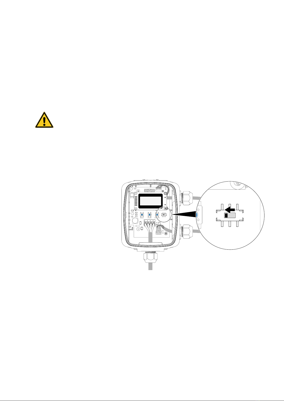
Selection of the output signal:
The differential pressure sensor is equipped with output signals for user selec-
tion of 4...20 mA, 0...5 V and 0...10 V. The factory setting for operation is voltage
output (0...10 V). The sensor can be changed to the current output mode by
sliding the output selection switch located on the printed circuit board from the
position marked VOLT to the one marked mA. See Figure 9.
mA VOLT
Figure 9
In voltage output mode, you can call up the corresponding user menu to select
between a 0...5 V and a 0...10 V output signal range.

9
Subject to technical modications
22PDP differential pressure sensor / Wiring
Wiring
Port wiring To avoid electric shock or device damage, deactivate the 24 V AC/DC power
supply until all of the connections to the device have been properly made.
Use shielded cables with corresponding core cross-sections for all connections
and do not route the device cables in the same conduit as the cables for supply-
ing inductive loads, e.g. motors. Establish all of the connections in accordance
with national and local regulations.
Undo the union nut of the cable gland at the underside of the housing to guide
the cable through the cable gland and into the housing.
Pull a sucient length of cable into the housing so that the cable conductors will
be easy to handle and no tensile force needs to be applied to the terminal. Com-
plete the wire connections in accordance with the wiring diagram for the appli-
cable power supply and the output signal type.
To simplify installation, you can remove the terminal from the printed circuit
board by pulling it upward and off the pins on the circuit board.
Ensure correct placement of the terminal after the wiring is completed. The la-
belling of the terminal pins on the printed circuit board must be visible in its en-
tirety and must not be hidden by the terminal.
Connect the DC plus or AC voltage hot side to the +/~ terminal (second pin from
the left). For the voltage output or the power supply, the DC ground or AC supply
common is connected to the /− terminal (rst pin from the left). Do not con-
nect any power to the AO and ZERO connections, because doing so would dam-
age the device. See Figure 10.
The analogue output is available at the AO connection (third pin from the left).
Check the analogue input of the controller to determine the correct connection
before applying voltage.
When using zero-point calibration with the remote Zero switch, connect it be-
tween ZERO (fourth pin from the left) and ground /– (rst pin from the left).
Screw the union nut of the cable gland on hand-tight after completing the wiring.

10
Subject to technical modications
22PDP differential pressure sensor / Wiring
Figure 10
In the event of a separate power supply, ensure that the grounding (DC) or
supply common (AC) are connected from the sensor, the controller and the
power supply.

11
Subject to technical modications
22PDP differential pressure sensor / Starting mode
Starting mode
The device switches into starting mode when it is supplied with current. The
LCD displays the current operating settings for 2 seconds.
All of the information in the menu and in the display are in English.
1. Software Version Number Version
2. Model Pressure Range
P Range
3. Output Type
Output
At the end of starting mode, the device switches into normal mode and displays
the measured differential pressure.
0.00
bar

12
Subject to technical modications
22PDP differential pressure sensor / User menu
User menu
The user menu can be entered at any time after starting mode by pressing the
<MENU> button. Please note that the <ZERO> button function changes to an
<UP> button function when a menu is active.
When this is the case, the differential pressure sensor interrupts operation and
retains the last pressure value as the output value.
If the user menu has been inactive for 5 minutes (no button pressed), then the
menu is exited and the device returns to standard mode.
The operation and parameters of the user menu are explained in the following.
Menu
Press the <MENU> button and release it again to call up the user menu.
Down/Up
This element appears only when the output signal switch on the circuit board is
in VOLT position. Use <DOWN> or <UP> to set the output signal type to 0...5 or
0...10 V. The factory setting is 0...10 V.
1. Output
(output signal voltage range) Output
0-10 Vdc
Press the <MENU> button to save changes and proceed to the next menu point.

13
Subject to technical modications
22PDP differential pressure sensor / User menu
2. Pressure Range
P Range
10 Bar
The pressure range is set by default to the largest range (1) of the model. Use
<DOWN> or <UP> to scroll through the four available model-specic ranges.
Available options are displayed as follows:
Pressure range in bar
Product type from Belimo 1 2 3 4
22PDP-185 5.0 2.5 1.0 0.5
22PDP-186 10.0 5.0 2.0 1.0
22PDP-189 35.0 17.5 7.0 3.5
Press the <MENU> button to save changes and proceed to the next menu point.
3. Pressure Scale
P Scale
0 - Max
The default pressure scale is uni-directional from 0 to the maximum range
(e.g. 0...10 bar). Use <DOWN> or <UP> to switch the setting to a bidirectional
scale or measurement (e.g. ±10 bar). The setting switches from "0 −Max" to
"+/− Max".
Press the <MENU> button to save changes and proceed to the next menu point.
4. Damping
(average value and signal
damping)
Damping
4 Sec
The default time for average value formation for signal damping is
4 seconds. This can be changed with <DOWN> or <UP> to 1...60 seconds.
Press the <MENU> button to save changes and proceed to the next menu point.

14
Subject to technical modications
22PDP differential pressure sensor / User menu
5. Output
(output signal direct/reverse) Output
Direct
The analogue output is set by default to direct (4...20 mA, 0...5 V or 0...10V).
<DOWN> or <UP> can be used to change this to reverse (20...4mA, 5...0 V or
10...0 V).
Press the <MENU> button to save changes and proceed to the next menu point.
6. Pressure Port
P Port
Direct
The pressure port is set by default to Direct (HIGH connection= higher pressure,
LOW connection = lower pressure). Use <DOWN> or <UP> to switch to Reverse
(HIGH connection = lower pressure, LOW connection= higher pressure) when
the connections need to be swapped in the software due to an installation error.
Press the <MENU> button to save changes and proceed to the next menu point.
7. Backlight
Backlite
Auto
The backlight is set by default to Auto operation. <DOWN> or <UP> can be used
to set it to Off, On, or Auto. Auto means that the LCD backlight lights up only
when a menu is being accessed, OFF means that it never lights up, and ON
means that it is always switched on.
Press the <MENU> button to save changes and proceed to the next menu point.

15
Subject to technical modications
22PD differential pressure sensor / Commissioning
Commissioning
Standard mode In standard mode, the device reads out the pressure transmitter and calculates
the differential pressure depending on the selected range. The differential pres-
sure is displayed on the LCD and is provided as current or voltage at the ana-
logue output. The output value is updated once per second.
To measure and display the differential pressure correctly, the pressure present
at the HIGH connection must be higher than that at the LOW connection. When
the pressure connections are switched, the sensor always outputs 0 V or 4 mA.
When this is the case, it is possible to switch the pressure connections in the
menu. It should be noted that, for correct measurement, the connecting cable
marked HIGH must always be connected with the HIGH pressure transmitter,
and the cable marked LOW must always be connected with the LOW pressure
transmitter.
If the LOW connection remains open to ambient pressure, then the HIGH
connection is used to measure a positive pressure.
To achieve a positive output behaviour, the pressure applied at the HIGH
connection for bidirectional operation should be higher than that at the LOW
connection. Negative pressure is displayed when the pressure at the HIGH
connection is lower than that at the LOW connection.
The differential pressure sensor shows a linear behaviour with respect to the
differential pressure measured and the corresponding signal output value. This
means for example that, for a 0…10 bar sensor in uni-directional operation, 0 bar
= 0V or 4 mA and 10 bar = 5 or 10 V or 20 mA, while in bi-directional operation
−10 bar = 0 V or 4 mA and +10 bar = 5 or 10 V or 20 mA. 0 bar corresponds in
this case to 2.5 or 5 V or 12 mA.
The output value can be inuenced by device settings, such as the time for
signal damping or average value formation.
The setting of the average pressure value calculations denes how many mea-
sured values are applied for averaging and thus as the basis for the output val-
ue. If, for example, the average pressure value calculation is set to 30 seconds,
then 30 one-second measured values are saved and averaged to form the out-
put value. The next second adds a new measured value and deletes the rst in
the series in order to calculate a new 30-second average for the output. The
output is updated every second with a new average value. The user menu can
be applied to set average value from 1 to 60 seconds.
In standard mode, the device also monitors the <DOWN>, <ZERO/UP> and
<MENU> buttons and initiates corresponding measures. The buttons are used
to access the user menu. The device also monitors the VOLT/mA switch to
determine the suitable output signal scale. The user menu can be used to set
the voltage range to either 0...5 V or 0...10 V.
Auto-Zero calibration An automatic zero-point calibration of the sensor can be initiated by pressing
the internal <ZERO> button and holding it down for a minimum of 3 seconds.
Once both pressure connections are near zero, the device calculates with a new
zero point. Automatic zero-point calibration can also be initiated by holding the
ZERO terminal for at least 3 seconds on ground potential by pressing the
remotely mounted Zero switch.
Generally speaking, performing a measurement range calibration in the eld is
not recommended. This holds true unless a high-quality calibration standard
with low differential pressure ranges is available and an unchanging sensor
temperature can be ensured during the calibration procedure.

EN – 2022-04/A – Subject to technical modications
All inclusive.
Belimo as a global market leader develops innovative solutions for
the controlling of heating, ventilation and air-conditioning systems.
Damper actuators, control valves, sensors and meters represent our
core business.
Always focusing on customer value, we deliver more than only prod-
ucts. We offer you the complete product range for the regulation and
control of HVAC systems from a single source. At the same time, we
rely on tested Swiss quality with a ve-year warranty. Our worldwide
representatives in over 80 countries guarantee short delivery times
and comprehensive support through the entire product life. Belimo
does indeed include everything.
The “small” Belimo devices have a big impact on comfort, energy e-
ciency, safety, installation and maintenance.
In short: Small devices, big impact.
BELIMO Automation AG
Brunnenbachstrasse 1, 8340 Hinwil, Switzerland
+41 43 843 61 11, [email protected], www.belimo.com
5-year warranty
Complete product range
Short delivery times
On site around the globe
Tested quality
Comprehensive support
This manual suits for next models
3
Table of contents
Other Belimo Accessories manuals


