*Teflon is a registered trademark of E.I. DuPont de Nemours and Company.
WARNING: HOT WATER HAZARD
Before draining the system, allow water to cool to at
least 100°F, open the drain valve (take precautions against
water damage) and leave the drain valve open until
servicing is complete. Failure to follow these instructions
could result in serious personal injury, death and/or
property damage.
REMOVAL OF PUMP FROM EXISTING SYSTEM FOR REPLACEMENT
WARNING: ELECTRICAL SHOCK HAZARD
Disconnect and lockout the power before servicing.
Failure to follow these instructions could result in serious
personal injury or death.
WARNING: ELECTRICAL SHOCK HAZARD
Be certain the electrical power is not present at the
motor leads before continuing. Failure to follow these
instructions could result in serious personal injury or death
WARNING: HIGH PRESSURE HAZARD
Pressure may be present in the pump body. This
pressure can be relieved by loosening the flange bolts and
shifting the pump assembly slightly to allow the pressurized
water to escape. Failure to follow these instructions could
result in serious personal injury or death.
1. Close the valves on the suction and discharge sides of the
pump. (If no valves have been installed, it may be neces-
sary to drain the system.)
2. Loosen the conduit box cover screw and remove the cover.
3. Disconnect the electrical supply lines to the pump.
4. Remove the flange nuts and bolts or loosen the union ring
nuts. Then remove the pump from the piping.
MECHANICAL SAFETY
THERMAL SAFETY
ELECTRICAL SAFETY
SAFETY REQUIREMENTS
WARNING: EXCESSIVE SYSTEM
PRESSURE HAZARD
The maximum working pressure of the pump is listed on
the nameplate –DO NOT EXCEED THIS PRESSURE.
Failure to follow these instructions could result in serious
personal injury, death and/or property damage.
WARNING: EXCESSIVE PRESSURE HAZARD
VOLUMETRIC EXPANSION
The heating of water and other fluids causes volumetric
expansion. The associated forces may cause failure of
system components and the release of high temperature
fluids. This can be prevented by installing properly sized
and located compression tanks and pressure relief valves.
Failure to follow these instructions could result in serious
personal injury, death and/or property damage.
WARNING: EXTREME TEMPERATURE HAZARD
If the pump, motor or piping are operating at
extremely high or low temperature, guarding or insulation is
required. Failure to follow these instructions could result in
serious personal injury, death and/or property damage.
WARNING: ELECTRICAL SHOCK HAZARD
Electrical connections are to be made by a qualified
electrician in accordance with all applicable codes,
ordinances and good practices. Failure to follow these
instructions could result in serious personal injury, death
and/or property damage.
WARNING: ELECTRICAL GROUNDING HAZARD
Adequate electrical grounding is required for the safe
operation of B&G Pumps. The use of grounded metal
conduit assures this requirement. If the means of connection
to the supply –connection box (wiring compartment) is
other than grounded metal conduit, ground the pump back
to the service. Use a copper conductor at least the size of
the circuit connectors supplying the pump. Connect the
ground wire to the green grounding screw in the wiring
compartment. Failure to follow these instructions could
result in serious personal injury, death and/or property
damage.
2
PUMP INSTALLATION
Locate the pump so there is sufficient room for inspection,
maintenance and service. Bell & Gossett recommends the
installation of service valves on the suction and discharge of
all circulators to facilitate servicing or replacement of the
circulator without draining the system.
Install suction and discharge flange connectors on the pipe
ends. The use of Teflon®tape sealer or a high quality thread
sealant is recommended.
Be sure to minimize any pipe-strain on the pump. Support the
suction and discharge piping by the use of pipe hangers near
the pump. Line up the vertical and horizontal piping so that the
bolt-holes in the pump flanges match the bolt-holes in the
pipe flanges. DO NOT ATTEMPT TO SPRING THE SUCTION
OR DISCHARGE LINES IN POSITION. THIS MAY RESULT
IN UNWANTED STRESS IN THE PUMP BODY, FLANGE
CONNECTIONS AND PIPING. The code for Pressure Piping
(ANSI B31.1) lists many types of supports available for various
applications.
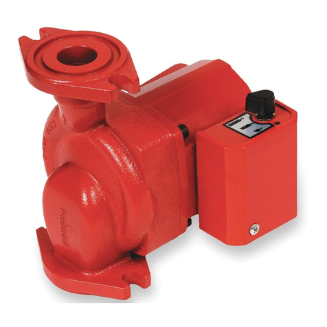
Bell & Gossett flange gaskets must be installed between the
NRF/NBF pump body flanges and the suction and discharge pipe
flanges. Use 7/16" diameter x 11/2" long cap screw and matching
nut to connect the pump to the flanges.
WARNING: RISK OF ELECTRIC SHOCK
Do not install this pump in swimming pool or marine
areas. Failure to follow these instructions could result in
serious personal injury, death and/or property damage.
CAUTION: The use of Teflon®* impregnated pipe
compound and Teflon®tape on pipe threads pro-
vides lubricity which can lead to overtightening and break-
age. Do not overtighten. Failure to follow this instruction
can result in moderate personal injury from hot water
and/or property damage.


