Bell and Howell 770 User manual
PHoToFACT* FolJ"t
tt1 \o
oE
-f rrj
r_o
Hd
la
do
AT
o()
ER
-r lr
J\
lll I
=o
Our
-l\
-N
1a
=\
lrrl\
6
vGENERAL INFORMATION
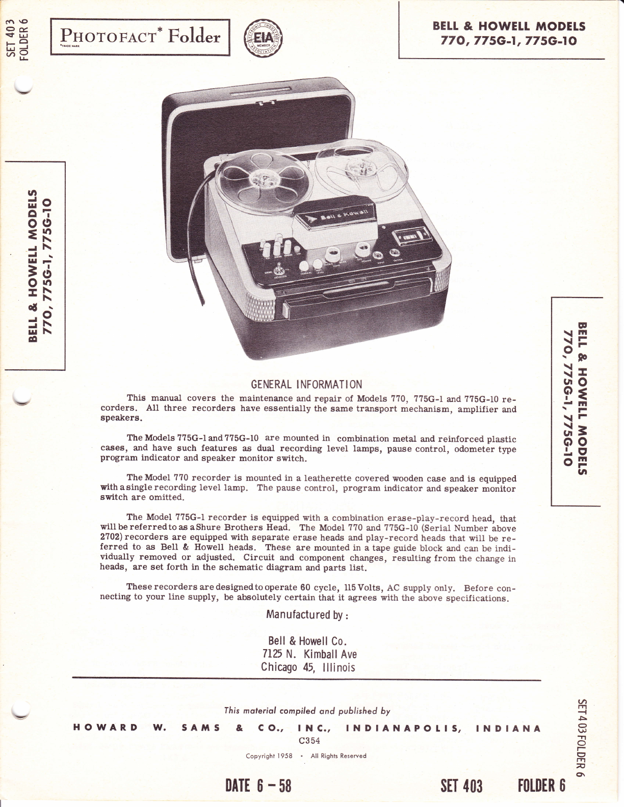
This manual covers the maintenance and repair of Models 770, 775G-1 and ??5G-I0 re-
corders. AII three recorders have essentially t}te same transport mechanism, amplifier and
spealcers.
The Models ??5G-t and ??5G-10 are mounted in combination metal and reinforced plastic
cases, and have such features a^s dual recording level lamps, pause control, odometer type
program indicator and speaher monitor switch.
The Model 7?0 recorder is mounted in a leatherette covered wooden case and is eguipped
withasinglerecording level lamp. The pause control, program indicator and speaker monitor
switch are omitted.
The Model ??5G-l recorder is equipped with a combination erase-play-record head, that
willbereferredtoas aShure Brothers Head. The Model 770 and 775G-10 (Serial Number above
2702) recorders are equipped with separate erlue heads and play-record heads that will be re-
ferred to as Bell & Howell heads. These are mounted in a tape gurde block and can be indi-
vidually removed or adjusted. Circuit and component changes, resulting from ttre change in
heads, are set forth in the schematic diagram and parts list.
Theserecordersaredesignedtooperate 60 cycle, 115Volts, AC supply only. Before con-
necting to your line supply, be absolutely certain that it agrees with the above specifications.
Manufactured by:
Bell & Howell Co.
7125 N. Kimball Ave
Chicago 45, lllinois
E
\ln
\i=
9;
\-
\I
F3
d lll
\r
\F
c==
oo
.|E'
oF
UI
BEIL & HOWELT NAODETS
77O, 775G-1, 775G-lO
sAfirs &
fhis moteriol compiled ond published by
co., lNc.,
c3 54
Copyright 'l 958 . All Rights Reserved
INDIANAPOIIS, INDIANA
a
trl
5
o
u)
Tr
o
(f
m
7
ch
sET 403 TOLDER O
vHOWAR.D l/.
DATE 6 .58
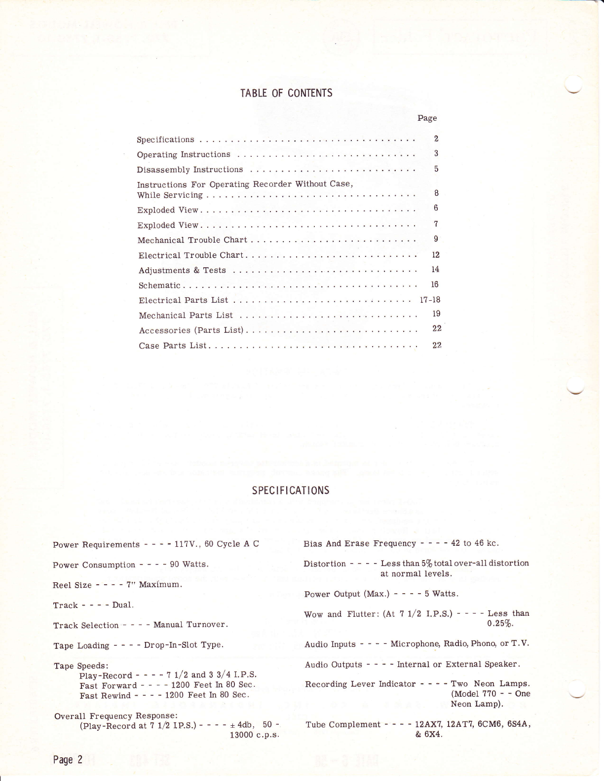
TABLE OF CONTENTS
Page
Specifications 2
Operating Instructions 3
Disassembly Instructions 5
Instructions For Operating Recorder Without Case'
WhileServicing... ....'. 8
Exploded View. . 6
Exploded View. . 7
MechanicalTroubleChart. ...... I
Electrical Trouble Chart. 12
Adjustments & Tests 14
Schematic 16
ElectricalPartsList .';...... l?-18
Mechanical Parts List i9
Accessories (Parts List). . 22
Case Parts List. . 22,
SPEC I FI CATIONS
Power Requirements - - - - 117V., 60 Cycle A C
Power Consumption 90 Watts.
Reel Size ?" Maximum.
Track----Dual.
Track Selection - - - - Manual Turnover.
Tape LoadinC - - - - Drop-In-Slot Type.
Tape Speeds:
Ptay-Record - - - - 7 t/2and 3 3/4 I.P.S.
Fast Forward - - - - 1200 Feet In 80 Sec.
Fast Rewind 1200 Feet In 80 Sec.
Overall Frequency ResPonse:
(Play-RecordatT l/2IP.s.) - - - - +4db, 50 -
13000 c.P.s.
Page 2
Bias And Erase Frequency - - - - 42 to 46 kc.
Distortion Less than 5% total over-all distortion
at normal levels.
Power Output (Max.) - - - - 5 Watts.
Wow and Flutter: (At 1 l/2 LP.S.) Less than
0.25%.
Audio Inputs Microphong Radio, Phonq or T.V.
Audio Outputs - - - - Internal or External Speaker.
Recording Lever Indicator - - - - Two Neon Lamps.
(Model?70--One
Neon Lamp).
Tube Complement - - - - 12AX?, L2AT1, 6CM6, 6544'
& 6X4.
OPERATING
Setting-Up The Recorder - MODELS 775
Open the recorder lid by pressing the gray buttons
located on eitler end of the carrying handle. Remove
the power cord from the rear storage section of the
recorder and plug it into a conventional 115 volt, 60-
cycle, alternatiqg current (AC) outlet.
Loading The Tape
This recorder will accept reels of tape up to ?"
in diameter. Before attempting to load the recorder,
depress the "stop"button (red buttonat upper leftside
of control panel). Place the empty reel on the right
hand spindle and the fuII reel on the left hand spindle.
The full reel should be mounted so that it will rotate
counterclockwise as the tape is unwound. Unrvind about
two feet of tape and lead it through the loading slot.
SIip the end into one of the slots in the empty reel. Be
surethat the tape isnot twistedandthat the emptyreel
witl fill as it rotates in a counterclockwise direction.
Turn the reel by hand to take up the slack.
Preparing To Record
Tape may be recordedeitherthrough themicro-
phone or Radio-Phono cord,bothof which plug intothe
"Inps1" jack. The microphone is used to make live
recordings, or it may be placed in frontof the speaker
of a radio, phonograph, or television set. The Radio-
Phono cord may be connected directly to the speaker
terminals of a radio, phonograph, or television set, thus
eliminating extraneous background noises which are
sometimes picked up by a microphone.
The microphone should be plugged into the INPUT
jackon the lower right side of thecontrol panel. Turn
the MONITOR switch on the left-hand corner of the
control panel to "NORMAL" position. This will dis-
connect the speakers and prevent squeal from acousti-
cal feed back.
Changing Speeds
The record or playback speed of the recorder
may be set to either 3 3/4 or 7 Lf 2 inehes per second.
The faster speed provides higher fidelity for recording
musical selections, while the slower speed has the ad-
vantage of longer continuous programming. To change
speeds move the SPEED CIIANGE shaft up or down; up
for 3 3/4" per second, down for 7 !/2" pet second. Be-
fore setting the shaft make sure the STOPbutton is de-
pressed. Operation of the recorder is the same for
either speed except for the setting of the SPEED
CIIANGE shaft.
Volume Control
The recorder is turned on by rotation of the
VOLUME control in a clockwise direction. The first
few degrees of rotatibnoperate the on-off switch;fur-
ther rotation increases the volume. The TONE CON-
TROL is not involved during recording but TONAL
balance is properly pre-set in the recording.
I NSTRUCT I ONS
Before starting to record, allow about on€ minute
for tube warrir up. Press the RECORD button down,
hold it there, and press the PLAY button to lock it in
place, This two-step operation prevents accidental
erasure of previous recordings.
Setting Record Level - M0DELS 775
The recording level is monitored by the twin
Record-Level indicator lamps. Adjust the VOLUME
control knob so that the NORMAL indicator flashes re-
gularly instep with variations of the recorded sound
level and the MAX. LEVEL indicator flashes ,inter-
mittently for peak variations. The level is too high if
both indicators flash almost eontinuously and too low
if neither one flashes.
Model ??0 has a single "record-level" lamp that
should flash during aII but the lowest passages.
Pause Lever - Models 775
The PAUSE lever, immediately to the right of
the RECORD button, can be used to temporarily halt
the travel of the tape without disturbing the settings of
other controls. This permits recordingor playback to
be interrupted without the "click"which would develop
if the machine were halted by pressing the STOP button.
The PAUSE lever is operated by sliding it tothe
left and holding it there for any desired interval. When
released, it slides back into pbsition, and recording or
playbackproceeds as before. ThePAUSE levercan be
useful in obtaining the proper volume level prior to
the actual recording. First turn the VOLUME. dial
counterclockwise to lowest level. Depress the RE-
CORD and PLAY buttons, then hold the PAUSE lever
to the left. Adjust the VOLUME dial for proper in-
dication by the Record-Level indicators, then release
the PAUSE lever.
Erasi ng
The recording process automatically erases any
previous material recorded on that track of the tape.
To completely erase a recorded track, remove all in-
put connections from the recorder, reduce volume to
Iowest level, and run the tape through in RECORD
mode.
Dual - Track System
The Bell & Howell Models 7?0 and ?75 are dual
track recorders. To record on the second haU of the
tape, turn the full reel over and place it on the left
spindlg after moving the empty reel to the right. Re-
thread the tape and proceed as before.
Using The Radio- Phono Cord
To record directly from the speaker of a radio,
phonograph, or television receiver, use the Radio-
Phono cord. Insert the plug on the Radio-Phono cord
into the INPUT socket on the lower right side of the
control panel. Connect the two alligator clips on the
opposite end of the cord to the speaker terminals.
F
\E
9;
\-
\rL
Fg
{.F
\F
L\3
oo
L9
oF
gr
TI
o
E'
trl
v
o\
Page 3
When t}te Radio-Phono cord is used, the program
being recorded can be monitored if the monitor switch
is moved to the "Monitor" position.
Tone Control
The TONEcontrolknob islocated directty tothe
Ieft of the VOLUME knob. Rotation of the knob in a
clockwise direction emphasizes the low frequencies
and subdues the high frequencies. Rotation in a
counterclockwise direction emphasizes the high fre-
quencies and subdues ttre low frequencies. No change
in volume is produced by a change in setting of ttre
TONE control.
Rewind And Fast Forward
When a tape has been completely played or re-
corded, press the STOP button to stop the recorder
(the STOP button can be used at anytime during any
moQe ofoperation). To return the tape back to the
original supply reel, press the REWIND button, then
use the STOP button when the tape is completely re-
wound. For rapid advanceof the tapein aforwarddir-
ection, press the FORWARD button. When either the
FORWARD or REWIND buttons are pressed the tape
travels at approximately 180 inches per second. Be
sure to take up any slack in the tape before using
either of these fast speeds.
The recorder is designed so that the STOP but-
ton must be pressed before changing from one mode
of operation to another. Thus to go from FORWARD
or REWIND toanotherfunction the machine must first
come to a complete stop. This feature protects the tape
from damage.
Program lndicator - Models 775
This feature is useful in'Iogging,'materialas it
is recorded or in relocating previously logged material.
The indicator should be set to "000" at the start of a
reel of tape, then any desirdd point on the tape can be
logged or relocated. The counter adds when the tape
travels in a forward direction and subtracts for the re-
verse direction, as during rewind.
Public Address
The Bell& Howell Model ??SGtaperecordercan
be usedasa public-address unit in the following manner.
Plug the microphone into the front panel INPUT jack
and turn the power on. Remove all tape from the re-
corder. Setthe MONITOR switchatthe "P.A." position.
Press the RECORDbutton and lockit inplace by press-
ing the PLAY button.
Keep the microphone to one side or behind the
speakers to avoid feed-back squeal.
Dictation And Transcription Machine
An ear-phone unit is available as an accessory.
With its use the recorder will periorm as a dictation
and transcription machine, Iimiting the sound to one
person.
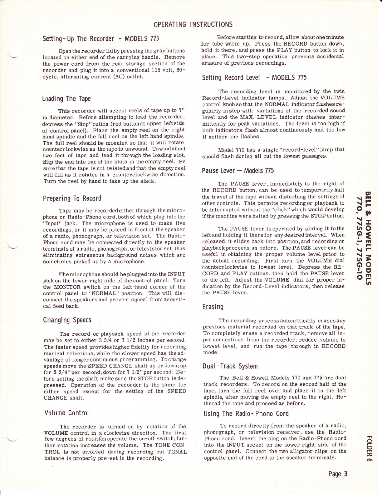
To Maximum
I ndicator
Lamp - To Normal
I I lndicator To I nput Jack
With Bell & Howell Head #I
ls Red and #2 ls Black.
To Play-
Record
Coil
Shure Brothers Head Lead
Color Code.
N0TE Bell & Howell Head Ass'y. Has
Black & Red Leads For Both
Record-Play & Erase Sections.
Erase Section Has Red Paint
Cable.
Lamp
With Shure Head
#l ls Black. #2 ls
Not Connected.
To Moniior Switch
Power
Transforme r
o\o
Page 4
FIGURE I.

-\
FLAY- RITSRT SWIT*FI ATTUAT Iru# t IT{K
5W tT*t.t
@ truTrRL$fiK MuTtrus srrurT*il@
FIGURE 2
D I SASSEMBLY I NSTRUCT IONS
EE
\ITil N
\-= :
e; b
\II
\II L
(lO )
P€ i
rm n
\FI
\F I
;r3 l
oo )
j.e 7
oF !
lnn
To Test 0r Replace Tubes
Remove the bottom grille assembly, held in place
by 4 Phillips headscrews. The two longer screws are
used for that side of the grille which has the name plate.
To Remove Amplifier And Tape Mechanism
From Case
1. Remove the two reel spindles held in place
by Phillips head machine screws and flat washers.
2. Remove PAUSE, VOLUME, and TONE control
knobs from their shafts.
3. Remove the top plate assembly (5) secured
in place by 4 Phillips head machine screws. This will
give access tothe magnetic head, Pressure padassem-
bly, idler drive wheels, upper linkage parts, Veeder
Root counter assembly, and level indicating lamps.
4. Remove the plastic carrying handle, secured
in place by two screws. On early models, screws are
accessible from under side of the handle.
5. Place the recorder in its upright position and
remove the two plastic feet, secured in place by the
Phillips head machine screws at the back of the case.
Remove the bottom grille as described under TO TEST
CR REPLACE TUBES.
6. Remove the two Phillips head screws aeces-
sible through the openings in the channel metal support
f or the plastic handle.
7. Withdraw the mechanism assembly from the
case, being caqeful not to damage the speaker cones.
Removal 0f Amplifier Assembly
1. Disconnect all plug-in leads shown in Fig. l.
NOTE: Refer to Figure 2 for location of items
mentioned below.
2. Disconnect the slide switch wire link from
the slide switch by first loosening the 3/9" switch
position adjustment nut.
3. Unsolder the leads to the on-off switch and
the interlock muting switch (M2 Fig. 2).
4. Unscrew the volume and tone control locking
nuts.
-rl
O
r
(3
fnj
nt
chl
1
)
7
1
)
\
Page 5
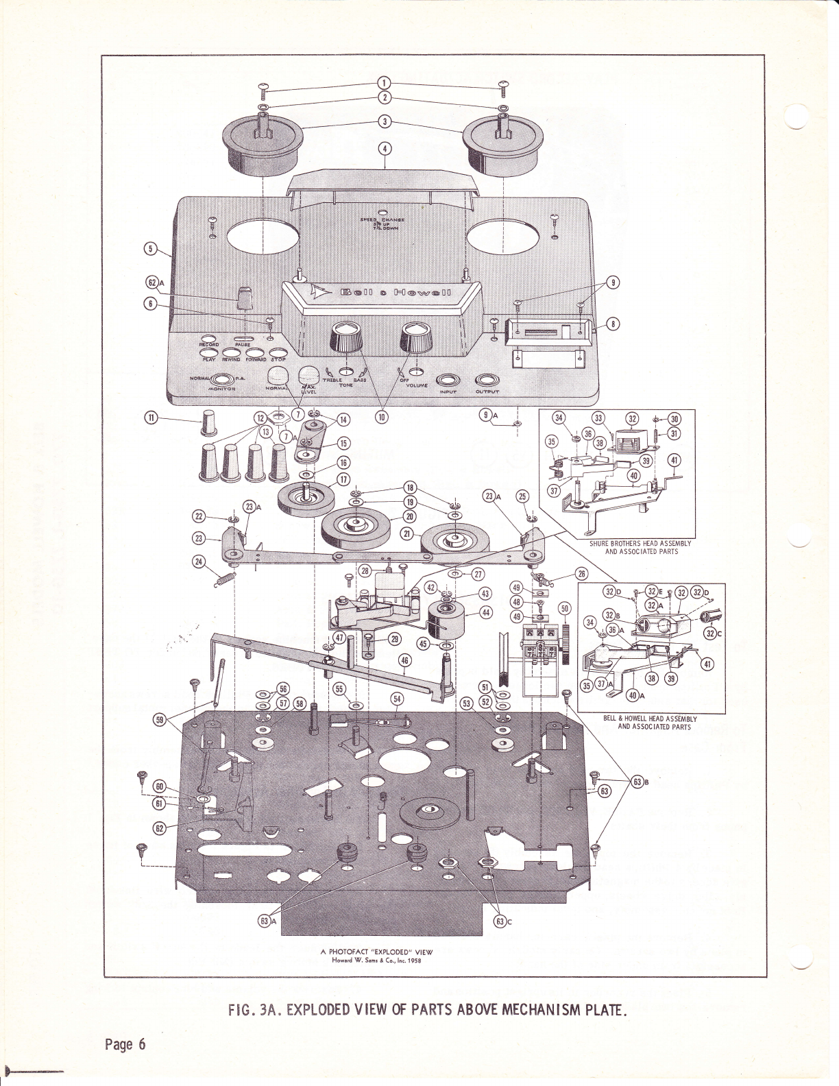
A P}..IOTOFACT "EXPLODED' VIEW
l'{oward \7. Samr & Co., lnc. 1959
F -- Page 6
F$G. 3A" HXPLCSED VIEW OF PARTS ABOVE MECHANISM PLATE"
w
\ lil
\i=
9;
\I
\'&
Hg
dm
\F
\F
gr\ 3
oo
Ltt
oF
ta
-?l
O
l-
(3
m
n
6
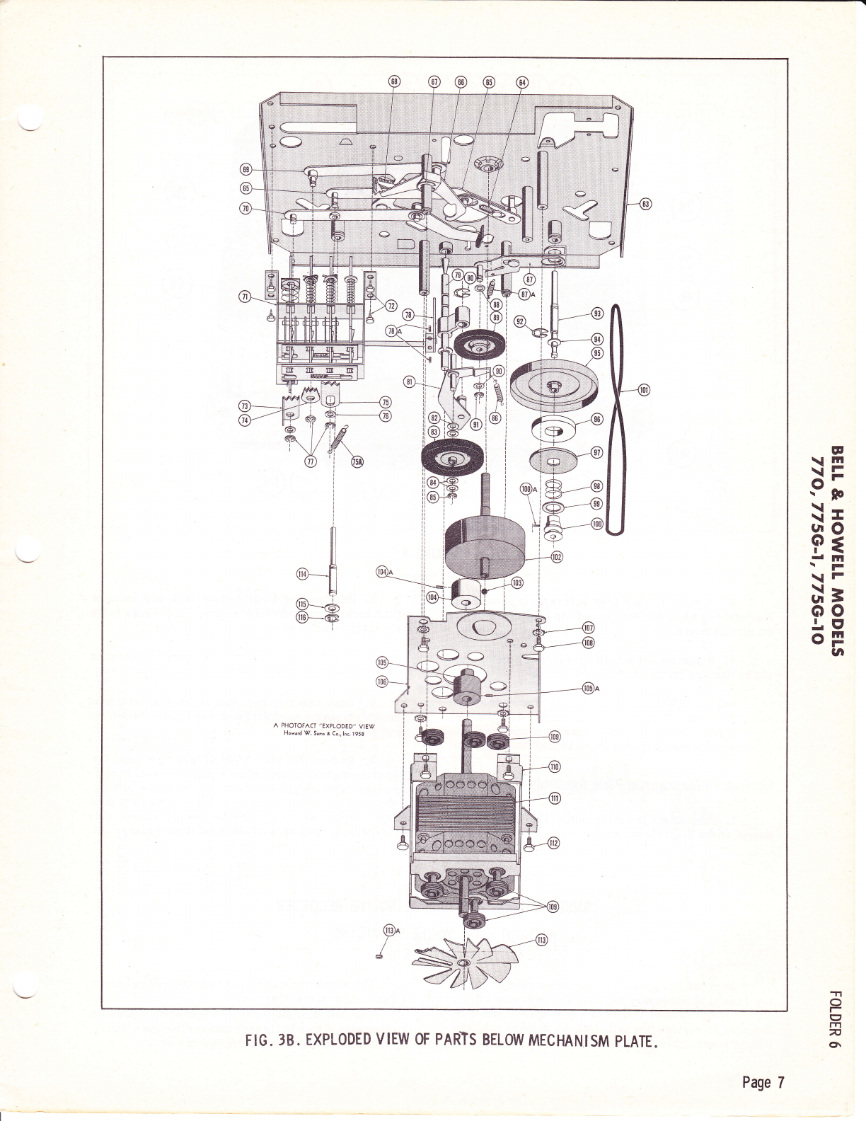
Page 7
F IG. 38 " EXPI-ODED V IEW OF PARTS BELOW MECHAN ISM PLATE.

5. Remove the six 1/4" self tapping screws and
flatwashers alongthe bottomand top edgeof theprint-
ed circuit board.
6. Withdraw the amplifier assembly,usingcare
not to damage the printed circuit board.
NOTE: After reassembly adjust the slide switch
position and securethe adjustment with the 3/8"
nut so that the slide switch makes proper contacts
when changing from record to play back position.
Removal 0f Mechanism Plate Assembly
1. Disconnect the drive motor (111) Ieads by re-
moval of the solderless connectors.
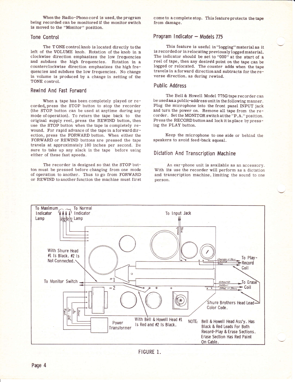
INSTRUCTIONS FOR
W ITHOUT CASE
In order to operate the unit when removed from
the case it is necessary to close the interlock switch.
Use a wedge to hold the swttch in a closed position.
Be sure to restore the interlock to normal condition
before reassembling the recorder.
Page 8
FIGURE 4
OPERATING THE RECORDER
WH ILE SERV IC ING
2. Remove the input, output jack and monitor
switch locking nutswhich hold thesecomponents tothe
main mechanism piate.
3. Remove the two indicator lamp assemblies
from the main mechanism pldte.
4. Disconnect the two cables of the magnetic head
assembly from the amplifier and free these cables from
their cable clamps.
5. Remove the six 5f16" self tapping screws that
hold the main mechanism plate to each speaker mount-
ing plate. The main mechanism platecannow bewith-
drawn,and the cirive motor,clutch assembly,and push
button control switches from the linkage system may
be inspected, cleaned, and adjusted if necessary.
The speaker cones should beprotected bycovers
of cardboard on masking tape.
The unit should be operated in anuprightposition
or otherwise supported in such manner that the ventilat-
ing fan is not obstructed during operation.

INTRODUCTION
E
\m
\itr
9;
\-
\I
Hg
I ltl
\r
\F
d=
oo
.|E'
OF
la
Troubles that may be encountered are arranged
in mechanical and electrical groupings, depending upon
origin. Due tothe fact thatsomedefects inreproduced
sound are actually of mechanical origin, troubles such
as "Wow" or "Flutter" and off pitch conditions are
listed as mechanical troubles.
Wherever reference is made to the use of lubri-
cants, apply only enough lubricant to coat the moving
surfaces. AII excess lubricant should be removed.
MECHAN ICAL TROU BLE CHART
SYMPTOM POSSIBLE CAUSE REMEDY
N,cisy push button operation. Lack of lubrication. Apply Belt & Howell # Spec. 1543 oil (Hodson
Gear OiI) to neoprene pads on push button
bhafts.
Vibration ncjise emanating
from case when in fast forward
or rewind position.
Top plate assembly seated im -
properly. Remove top plate assembly (5 l.ig. 3A) and
bend the front end of top plate down slightly so
when secured in place the front edge will seat
against the tape recorder bottom case assem-
blv.
Volume or tone controls bind
and are difficult to turn. Printed circuit assembly not
centered.
Lack of lubrication or "tacky"
condition of rubber grommets.
Reposition assembly, align shafts intorubber
grommets
Check condition of rubber grommets where
tone and volume control shafts pass through
main mechanism plate. Lubricate rubber
grommets with DOW-Corning 200-350CS fluid
silicon grease.
Clicking noise when recorder
is in fast forward or rewind. Check Veeder Root counter for loose springs
or lackof lubrication. If necessary, lubricate
gear teeth with DOW- Corning 200- 350CS fluid
silicon grease.
TI
o
I
1T'l
v
o\
Damaged Veeder Root counter.
Page 9

FIGURE 6
MECHAN ICAL TROUBLE CHART (Conti nued)
SYMPTOM POSSIBLE CAUSE REMEDY
Case upper lid assembly witl
not lock properly. Alignmentof locking prongs in-
coruect. Bend the two locking prongs riveted to the
upper lid assembly approximately ten degrees
inward and to the right or left as required tcr
make proper contact with the lock catches in
the lower case assembly.
Speed change shaft binding. Lack of lubrication. Apply lubricant, BeII & Howell Spec. #1i44
(Hodson non-melting white lubricant) to speed
change shaft.
Drive erratic on both speeds. Position of drive pulley (105 Fig.
3-B) incorrect. Check position of drive pulley on drive motor.
Loosen Allen screw and position bottom of
drive pulley to distance of .218 to top of motor
shell.
Thumping or scraping noise
when in forward or rewind
position.
Position of forward and rewind
pulley (104 Fig.3-B) incorrect. If position of forward andrewind putley is too
high on its shaft, it will scrape the underside
of the top plate assembly; if position of pu.lley
is too low, the Allen screw opening in the
pulley wiII strike against the rubber molded
wheel. Readjust as necessary.
Take up reel doesn't revolve in
play or record position. Take-up idler spring (87A Fig.
3-B) off or broken.
OiI on take up idler rim (gb Fig.
6).
Clutch slipping on clutch wheel
assembly.
Replace.
Moisten cloth in alcohol and clean surface of
rubber rim.
Reposition elutch pulley (100 Fig. 6)on shaft
and tighten Allen screw.
Take up reel does not revolve
in fast forward position. OiI on rim of fast forward idler
wheel (21 Fig. ).
Fast forward Iever spring (75A
Flg. 6) off or broken.
Moisten cloth in alcohol and clean surface of
rubber ri m.
Replace.
Page I0

MECHANICAL TROUBLE CHART (CONti NUEd}
SYMPTOM POSSIBLE CAUSE REMEDY
Fast forward idler spring (64
Fic. 3-B) off or broken. Replace.
Supply reel does not revolve in
rewind position. OiI on rewind idler wheel (1? fig.
4) or rewind drive wheel (20).
Rewindidler spring (68 Fig. 3-g'1
off or broken.
Moisten clothin alcohol andclean surfaces of
rubber rims of (1?) and (20).
Replace.
Reels do not stop when stop
button is depressed. Brake actuating spring (28 Fig.
3-,A) off or broken.
Brake lining worn.
Brake lever (?8 Fig. 6)loose on
shaft.
Replace.
Replace. (See Adjustments & Tests.)
Reposition brake lever (?B) and tighten AIIen
screws,
Counter mechanism does not
operate. Defective counter
Counter belt (101
broken.
(50 Fig. 3-A).
Fig. 7) off or
Check gear teeth incounter lor damage. Re-
place if necessary,
Replace.
Wow; flutter or chirps. Improper pressure between
capstan (102 Fig. 4) and pres-
sure roller (44).
Excessive takeuP tension.
Counter (50 Fig. ?)binding.
Dirty pressure pads (38 Fig. 3A)
Pressure roller (44 Fig. 3A)
binding on shaft or damaged.
Scored flywheel shaft (102 Fig.
4) or flywheel shaft bearings.
Worn idler wheel assembly (83
Fig. 3-B).
Bent fan blades (113 Fig. 5) or
bent motor shaft.
See Adjustments & Tests.
See Adjustments & Tests.
Check for chips or dirtingears and for scored
shaft. Cleanand lubricate. UseDow-Corning
200-350CS fluid silicon grease.
Saturate with alcohol. Brush contact gurfaces
in direction of normal tape travel,
Remove roller and clean bearing with pipe
cleaner dampened with alcohol. Clean roller
stud, if scored, polishwithcrocus cloth. Apply
a light coating of Hodson 2-4?8 non-melting
grease to the stud before reassembling.
If shaft is only lightly scored, polish with
crocus cloth. WARNING: DO NOT USE
EMORY CLOTH. If bearings are scored,
drill out rivets, remove bearings and replace
them.
Some dents in the drtving surface can be
ironed out by pressing the flat side of a screw
driver blade against the tire,while the wheel
is revolving. If tire is nicked or torn, replace
the wheel assembly. Apply a light coating of
Hodson 2-4?8 non-melting grease tothe stud,
before reassembling.
Place fan (hub up) on a flat surface. The ends
of all blades shouldcontact the surface. If any
blades are out of alignment by more than
0.015", reshape those blades. If motor sha"ft
is bent, replace the motor.
E
\E
9;
\-
\I
sio
P{
.-F
\F
Or\ 3
oo
Lg
oF
UI
Pitch of sound, from pre-
recorded tape is low. Capstan drive mechanism is
slipping. Remove top panel (5 Fig.3A). Dampen a pipe
cleaner with alcohol and clean aII driving
surfaces. NOTE: All driving surfaces can
bereached thru holes inthe mechanism plate
T1
o
I
ta1
n
cn
Page ll
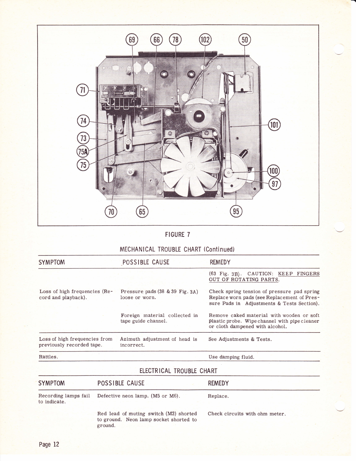
FIGURE 7
MECHANICAL TROUBLE CHART (Continued)
SYMPTOM POSS IBLE CAUSE REMEDY
(63 Fig. 38) . CAUTION: KEEP FINGERS
OUT OF ROTATING PARTS.
Loss of high frequencies (Re- Pressure pads (38 &39 Fig.3A) Check spring tension of pressure pad spring
cord and playback). Ioose or worn. Replace worn pads (see Replacement of Pres-
sure Pads in Adjustments & Tests Section).
Foreign material collected in Remove caked material with wooden or s.oft
tape guide channel. plastic probe. Wipechannel with pipecleaner
or cloth dampened with alcohol.
Lossof high frequencies from Azimuth adjustment of head is See Adjustments & Tests.
previously recorded tape. incorrect.
Rattles. Use damping fluid.
ELECTR ICAL TROUBLE CHART
SYMPTOM POS S I BLE CAU SE REMEDY
Recording lamps fail Defective neon lamp. (M5 or MG). Replace.
to indicate.
Red lead of muting switch (M2) shorted Check circuits with ohm meter.
to ground. Neon lamp socket shorted to
ground.
Page 12

EI-ICTRICAL TR0UBLE CHART (Continued)
SYMPTOM POSSIBLE CAUSE REMEDY
Cold solder connection to record-play-
back switch (M1). Reheat solder connection.
Motorboating. l2A)K7 tube defective or not fully seated
in socket. Check and replace as necessary.
Right speaker dead. Left speaker lead shorted to ground. Make visual check.
Distortion. Black Iead of speaker harness loose.
Defective 12AT? or 6CM6 tube.
Defective record level neon Iamp.
Hum control (R3) center rotating section
shorted to ground. Resistance of center
section to ground should be 2?0 ohms.
Resistor R16 (22K ohm in plate circuit
of 12AT?) open.
Make visual check.
Test and replace if necessary.
Test and replace if necessary.
Check with ohm meter.
Check with ohmmeter.
Low Output. Recording level too low.
Record current too low.
Foreign material on tape guide
or head.
Worn head pads or insufficient
pressure.
See Power Output test under Adjustments &
Tests. Check microphone.
See Adjustments & Tests.
Remove.
See "Loss of High Frequencies".
E
\ Itl
\itr
9;
\-
\I
F3
d lfl
\F
\F
d=
oo
.!. I
oF
(a
Low Output and Distortion. No bias or low bias. Oscillator coil open. Shorted
Record-Play srvitch (M-1) not
Check bias. (See Adjustments &
Remove.
erase head.
functioning.
Tests).
Foreign material on tape guide
or head.
Poor Iow frequency Defective magnetic head assembly.
response. Replace.
Low sound output. Tone control (R2) shorted togroundatthe
capacitor network C12 and C13. Check with ohmmeter.
6X4 rectifier plates
red hot. RedB leads oi power transformer shorted
to ground.
B+ filter capacitor shorted.
Check with ohmmeter.
Check sections A and B of filter capacitor C1
and replace if necessary.
Hum. Open hum adjusting control (R3).
Printed circuit wiring from output trans -
former frame to filter capacitor open.
Cold solder connection of capacitor C4,
.1 mfd (in input circuit) .
Cold solder connection of output trans-
former frame.
Cold solder connection of rectifier tube
retaining spring where attached to power
transformer shell.
Replace.
Check with ohmmeter.
Reheat the solder connections.
Reheat the solder connection.
Reheat the solder connection. O
E2
la1
n
o\
Page 13
ELECTRICAL TROUBLE CHART (Continued}
SYMPTOM POSSIBLE CAUSE REMEDY
Defective tubes.
lzA)K'l tube shield missing or not making
firm contact against ground lip.
AC line cord polarity.
Condition and,/or position of felt erase
pad improper.
Check and replace as necessary.
Replace shield; bend Iip to make firm contact.
Reverse polarity of AC line cord in wall re-
ceptacle to obtain minimum hum.
The top of the felt pad must pass just beneath
the magnetic head shield front edge cut out.
If frayed, the felt pad should be replaced.
Internal or external
speakers do not.oper -
ate.
Defective monitor switch (M4).
D6fective muting switch (M2).
Check with ohmmeter.
Check with ohmmeter.
Excessive hiss in re-
cord and playback. Noisy 12AX? and,/or l2ATl .
Magnetized Rec or d -playback,head.
Substitute new tubes and test for noise.
Use head demagnetizer on head. (Note: it
is considered good practice to demagnetize
heads after e4ch 10 or 20 hours of use.)
Plays back pre-
recorded material
but will not record.
Defective 654.A tube.
Defective oscillator coil (L1).
Test and replace if necessary.
Test and replace if necessary.
ADJUSTMENTS
lnterlock Adjustments
The interlock switch is a DPDT spring loaded
switch, which opens the AC input line when thebottom
grille assembly is removed from the case. If this
switch fails to operate properly it may be due to poor
lead contact connections or to mechanical reasons.
The switch should close when the bottom grille
issecured in place. If it failsto doso,checktheheight
of the switch arm which operates the interlock, The
end of this arm should be from 7/8,'to 1" above the
grille assembly for proper srritch operation.
lmproper Tracking 0f Tape Reels
The feed and take-up plastic reel spindles are
identical and are held in place with PhiUips head screws
and flat washers. The reel spindles are mounted on a
flanged shaft. If the plastic reel spindles wear and the
tape scrapes on the reels, shim washers can be added
between reel and flange shaft until the reels are in prop-
er alignment. The PLAY button should be depressed
Page 14
AND TESTS
whenever the spindles are being replaced in order to
prevent damage to the cork brake lining.
Adjustment 0f The Recording Gase
Locking Mechanism
1. Remove the two plastic latch release knobs
by pulling them straight out, away from the case.
2. Remove the two Phillips head machine screws
visible through the smallopenings in the metal handle
bracket.
3. Drive out the two roII pins that secure the
handle bracket to the two spring loaded shafts by the
following method:
a. Place the handle bracket on a lirm surface
and use a 178" hard steel rod to drive out the
roll pins. Do not usea pointed rodor theroll
pins will spread and be very difficult to re-
move.
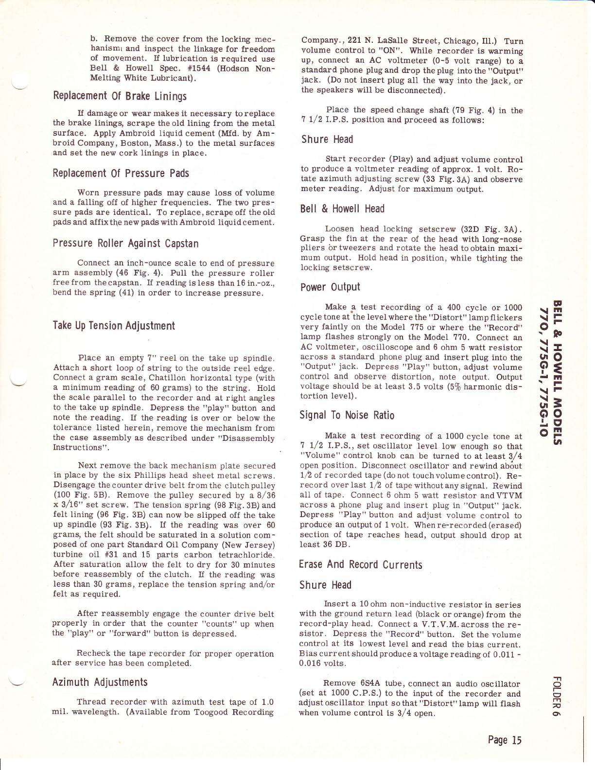
b. Remove the cover from the locking mec-
hanismr and inspect the linkage for freedom
of movement. If lubrication is required use
Bell & HoweII Spec. #1544 (Hodson Non-
Melting White Lubricant).
Replacement 0f Brake Linings
If damage or vt/ear makes it necessary to replace
t}te brake liningg scrape the old Iining from the metal
surface. Apply Ambroid liquid cement (Mfd. by Am-
broid Company, Boston, Mass.) to the metal surfaces
and set the new cork linings in place.
Replacement 0f Pressure Pads
Worn pressure pads may cause loss of volume
and a falling off of higher frequencies. The two pres-
sure pads are identical. To replace, serape off the oid
pads and affix the new pads with Ambroid liquid cement.
Pressure Roller Against Capstan
Connect an inch-ounce scale to end of presbure
arm assembly (46 Fig. 4). PulI the pressure roller
free from thecapstan. If reading is less than 16 in.-o2.,
bend the spring (41) in order to increase pressure.
Take Up Tension Adjustment
Place an empty ?" reel on the take up spindle.
Attach a short loop of string to the outside reel edge.
Connect a gram scale, Chatillon horizontal type (with
a minimum reading of 60 grams) to the string. HoId
the scale parallel to the recorder and at right angles
to the take up spindle. Depress the "play" button and
note the reading. If the reading is over or below the
tolerance listed herein, remove the mechanism from
the case assembly as described under "Disassembly
Instructions".
Next remove the back mechanism plate secured
in place by the six Phillips head sheet metal screws.
Disengage the counter drive belt from the clutch pulley
(100 fig. 5B). Remove the pulley secured by a8/36
x 3/t6" set screw. The tension spring (98 Fig.38) and
felt lining (96 Fig. 38) can now be slipped off the take
up spindle (93 Fig.3B). If the reading was over 60
grams, the felt should be saturated in a solution com-
posed of one part Standard Oil Company (New Jersey)
turbine oil #31 and 15 parts carbon tetrachloride.
After saturation allow the felt to dry for 30 minutes
before reassembly of the clutch. If the reading was
Iess than 30 grams, replace the tension spring and,/ar
felt as required.
After reassembly engage the counter drive belt
properly in order that the counter "counts" up when
the "play" or "forward" button is depressed.
Recheck the tape recorder for proper operation
after service has been completed.
Azimuth Adjustments
Thread recorder with azimuth test tape of 1.0
mil. wavelength. (Available from Toogood Recording
Company., 221 N. LaSalIe Street, Chicago, Ill.) Turn
volume control to "ON". While recorder is warming
up, connect an AC voltmeter (0-b volt range) to a
standard phone plug and drop the plug into the "Output"
jack. (Do not insert plug all the way into the jack, or
the speakers will be disconnected).
Place the speed change shaft (79 Fig. 4) in the
7 l/2 I.P.S. position and proceed as follows:
Shure Head
Start recorder (Play) and adjust volume control
to produce a voltmeter reading of approx. 1 volt. Ro-
tate azimuth adjusting screw (33 FiS.3A) and observe
meter reading. Adjust for maximum output.
Bell & Howell Head
Loosen head locking setscrew (32D Fig. 3A).
Grasp the fin at the rear of the head with long-nose
pliers br tweezers and rotate the head to obtain maxi-
mum output. Hold head in position, while tighting the
locking setscrew.
Power Output
Make .a test recording of a 400 cycle or 1000
cycle tone at the level where the "Distort" lamp flickers
very faintly on the Model ??5 or where the "Record"
lamp flashes strongly on the Model ??0. Connect an
AC voltmeter, oscilloscope and 6 ohm 5 watt resistor
across a standard phone plug and insert plug into the
"Output" jack. Depress "Play" button, adjust volume
control and observe distortion, note output. Output
voltage should be at least 3.5 volts (5% harmonic dis-
tortion Ievel).
Signal To Noise Ratio
Make a test recording of a 1000 cycle tone at
7 l/2 lrP.S., set oscillator level low enough so that
"Volume" control knob can be turned to atleast 3/4
open position. Disconnect oscillator and rewind ab6ut
12 of recorded tape (donot touchvolumecontrol). Re-
record over last l/2 of tapewithoutany signal. Rewind
all of tape. Connect 6 ohm 5 watt resistor andVTVM
across a phone plug and insert plug in "Output" jack.
Depress "PIay" button and adjust volume control to
produce an output of 1 volt. When re-recorded (erased)
section of tape reaches head, output should drop at
least 36 DB.
Erase And Record Currents
Shure Head
Insert a 10 ohm non-inductive resistor in series
with the ground return lead (black or orange) from the
record-play head. Connect a V.T.V.M. across the re-
sistor. Depress the "Record" button. Set the volume
control at its lowest level and read the bias current.
Bias current should produc e a voltage reading of 0.01 1 -
0.016 volts.
Remove 654A tube, connect an audio oscillator
(set at 1000 C.P.S.) to the input of the recorder and
adjustoscillator input sothat "Distort" lamp will flash
when volume control is 3/4 open.
IE
\lrll
\=
9;
\-
\I
$3
dln
\F
\F
il=
oo
.!. El
oF
vl
-1
o
|-
U
7
o\
Page 15
(o
I
o
o
\r
l4l t!
>g >H
Pe 33
(\ (/) F.(/l
IJ
(J
E
o
tt
>'
o
\o.
(\T
!z
o
o-
F
=
o
@@
\Z
C\I
c!
@
(tt
F
z.
l4J
=
J
E
o
,/*
@
@
+!Jr F'
co -E
@'=
\Z
c
C\f
(\!
o@
@FT
Lix
E\O
@
-N
=k
r! 6{
<F ao
@
-t
lrJ
a
o
=
z. >.
o=
oo
lrl -
(,=
JN
*a
X,I
=2.
o
O
J
E
lrj
rJ\
I
l4l
z
o@
'@5s
iir''
@
^N
=t
*S
e
)>
=6
;E
L) e4
!o
=o-
a>
qd
t3z
uJ-
EZ
l=
5F
a- (/l
\.,
F
:
tal
I
v
z. att
o
:. Zo
-a oB
3 6 k!
!
'<, sF h I
dff(e 23
z=:-,-.d
=7.2? ; E
v;-F *a
sx=E 2;
2 *&,2. { 'o
LL
ze . a
r!>ci6 qt r
EgHu ,-*
d:F==
= =.n.tt
t/)o<< .i
Ea== P
i4, I
<=+l;l
tt,
(9
z.
o
lrl,
G,
r4J
(J
z.
F
V,
a
lrj
&,
b
9";J
E .39- .,q
O no c-o :i
E PTEEE
r -id.!R
.=
5 = 9 E €= ; E
su.EsSq.E-e
-c s= c- J o=
E E:3*E F i
=€ !e;E; R
E= E H= E F g
€I !EE s9s
E g r H.EE i:E
p rE€ =El;
FsE€g:;E
EEg A =.=E E
3?,Hg.5E E=
-j c.; ,ti s .i .o
ul
z
&
trl
\6
E,F
o<
tr. (J
.J
EI
J<
oc,
Eo
fg
ui
6>
o
\Z
c
t\
st
N-
@
@
@tF
V,
c
LN
cis
-r--Jl,'
I
I
I
@
T--
I
I
I
=l
HS
T
@tE
c.l E
BB,.
d CJN
o5F
<=
(9:c b-
zc) o
-5 I
3i !r,
E l--^rff-l1, e
o{ @ '' ,------.,
s =a
-:.5 \9
-tf.]5, *
ARE
lgl--{f
\c@
R
x@5 l: It'
-.1
p=l
=3t
6l
-F9{
z.z I
ool
f-
!Z
(-)
o:r
*E
z=^
FI
z.i
rd!
=!
(9!
UI
vtl
-t
c|l
FI
=!
Wri
oAl I
it
N
(J
l!
O
z.
o
F
O
z.
D
-
o
F
o\
cc
o
oo
o
c
o
oc
o
a
I
o- o
o
!n
c
o
o
n(J
zc)
z.
C
;Y,
o
F\
v.
olZ
6 <\l
NN r
c
o
F-
GI c)
z.
z.
=
\Z
o
N
o-
\z
o
€\Z
o\z
ct
-t !z
( T
GI c
a
(\J
o
oo
oc
ac
o
o(J
z.
o
o
fn o
oo
o
(Y\
G
o
oc
o
o
(Yl
o
c
o
oY,
o
t\ v
GI
Rl c
(f
o
gr
t\
ir c
o()
zc
o
oo
\o (J
z.
\Z
o
6
*v
oc
o
o
o
+(-)
zc
C:'
n
t&
cr
tr
t\
x
(\I
t\
F
(\r \o
=
c)
\o rq
a,fl
\o
F
(9
-l
x
\o
=
lrl
Fir rn
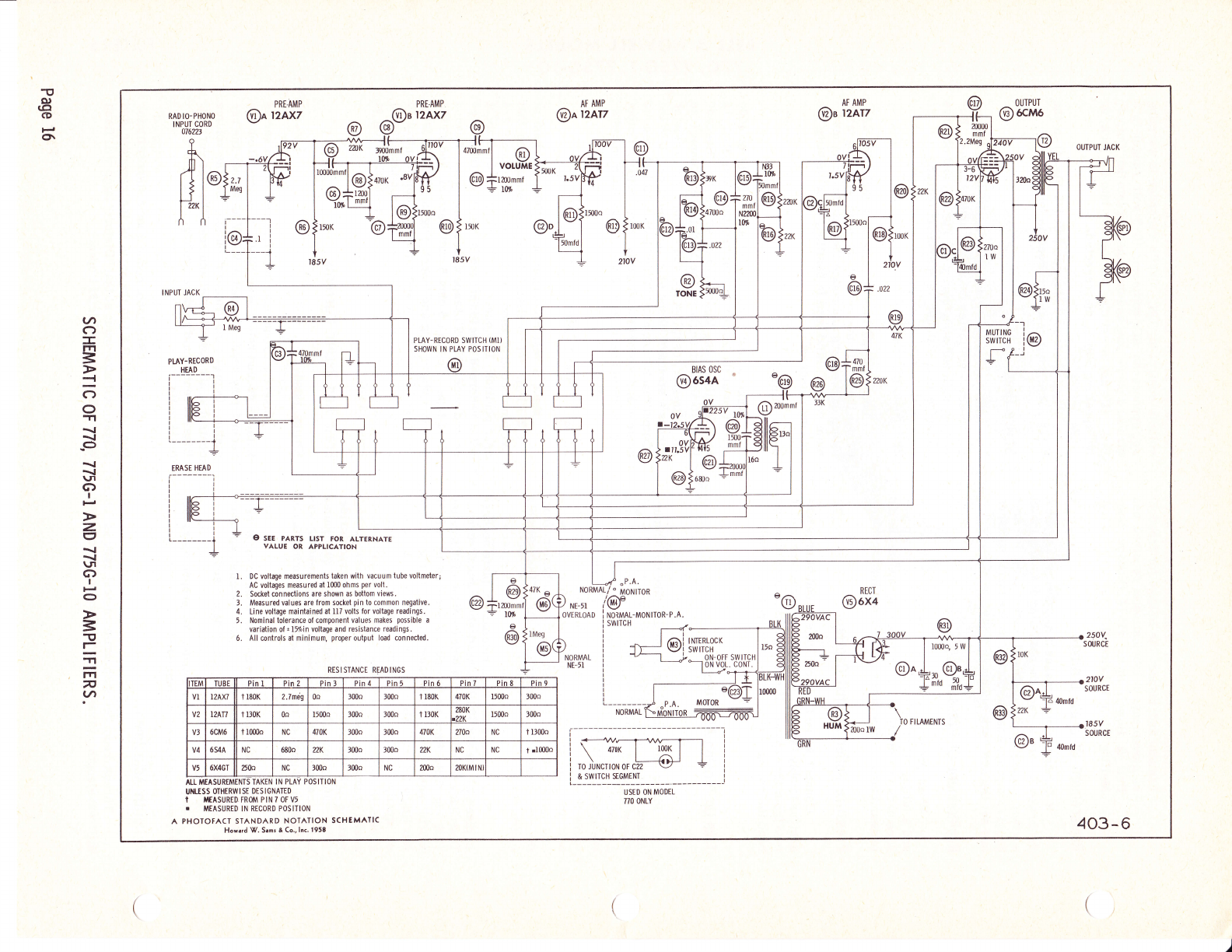
SCHEMATIC OF 77A, 775G-1 AND 775G-IO AMPLIFIERS.
Page t6

=
EI
I
o
o
l-
I
ra
I
rn
tn
I
I
(,
v,
J
o
&
F
z
o
U
g
AFg
=5rh
Ft-!
rh{hh
+) li CL
hF-
geE
EEE
E!q5
(JYo.
E Ad R
F a'* I
ut q 9n
E Et.=
- t.
5 ts d>
FR >.9 B
o o-co
o€d
H .$ eu
E 3 rar'= E
E i-.v> g
Ozrsl!iO
l- =oc?ua
s\ e .T^r
or^ o(d)ar
(,)= (a; (n
:.i:E: F
FsFEF;
€E-€-d h
FF.dg
Eqeot>
gE= B= I
+s+ B+ H
lo trro.!lo c
l- .d t- lrJ t- d
F-€r Hr-rC
sS!;.eH
o5q)(l)(D5
E:E FEx
> u : E>2,
oo@o@o
o
O. t;
x!
Lf,
oo
bA E
;o
;(J
V,E.:
C,.E E
esE
E Y
f\J
rc
(J ET
<r;
t3g
e€E
OL
ALO
il:I
X;E
lJ- c E
.! .s
5)j
,atr
go\
o:'
>.=
tJ
'uo
oo.
o.o
o9
L)
vt
c,
o
=
I
G
(J
(J
-
F
J
o
c,
F
u
IJJ
J
ItJ
tn
Z2
o=
r-
E;
r\_
4 -v,
(J.,'
ni
AU
ot
Zs
hz
=9
tllvt
blrt
uq
4
.n
o
F
E'
lrt
v
o
ts
q)
b0
o
cd
cl
(.)
I
o'
z
i
v)
tll
o
z
z
o
J
.n
z
E
a
o
F
o
F{
Fa
F
.;
op
g
i Hg
o oa
o
z
tll
=
ur
()
J
A
tlt
e,
Et
==
o
,Z
EF
g
<ct
a/tt L
Or-
E. d,
do-
ao
<ct
<z
g.F
a- d.
z<
u.l o-
(J
o)
Fci
O-
L
€iv
-r<
EA
n
Eor
:i tt{
K9
oo
FF
@
o
o
6l
o
t-
lt/)
IF
IF
t<
gl3
k l*-
c, l.ng
tvr.L
l--{
ilN -.
v3tse
odoo
o tsoo
lr?raloN
Fi Jtr*-
tr dd
R- R
6lca 6t
rv zz z
S SSSoo$SoSoSS
c0 @ 6D O {r,< c\ O E- <{ CO ot CO @ \i @ c\l O) .(l| O 6a
o) o o) cD o o) o) o) or o) o) co co o) o) o) o 6) o! o) o)
t- € t- t- F t- t- E- t- c0 t- t- t- t- F I- @ F t- t- t-
dr-addHdtlFlFt Fad- -id
ooooooooooooooooooooo
t- E- I-, r- t- r- t- t- t- r- F t- r- t- E- t- F r- F F r-
o
z
UI
=
u,l
Ez
:3
o
ca
:F+RqRqnqs$ $q Hnqsq
gHHgH*Hg6RH HH #gHgH
t- t5 '<
n +, i Kor c\ 6l
Ea q EEE E q H
OC) O UF]O O O O
<A p <o<
6l
ctN
Fa
o:r
Htqagf?aana as
*BHEHHHHHEH HH
T?qT H BqF?
eAOCItoAOAO
aanoaooao
a- .. 3 qe$ $^ HF* a
z? ? I *,2*, *,? 95? q
Ra I I SH$ FR asa R
Am Fq O o{AA AQ E:A ca
5e
>.-
9E
ur{
<o-
l^oo
I :<aOOOcrF- 61 crlQ -t-R
lO ;<=OOO=r{iaNO c\IOOO)<OXX
i5 :E XRs 5 E???F3?R5R ERX=
F
o
:
A.
s
o:r $,., co F oo o, I = E 3 g I I = 99 R R S R
Oc)OOOC)UOOOOOOOO(JOOOUO
o
z
llj
=
llJ
U
o-
Iu
e,
Hct
oL
SE
o.<
art G
**
$cD
co co
(9 c0
6lN
trE
3:
9p
3f
oci
2z
{r-
r, &,
rs
a_d
oz
*=
-ls ci
frggz
4ia
8ds
5e
>.-
9E
ur{
<a-
o
tct
,ra Z-
caE
Ef
nO-
o@
@c0 -
oo
l- C-
0
z
F
ooo oo
l()rt!lt?oolJ"
r$ 6'A N Cra 6a C\
4o-
U^o oo^
H6o<,<rH
-{ l.$ a r-{
{.r
UJ:
l-z SEU*no
OU
o
LU
o
z
UJ
o- t-t
#E
llJ
./,
f9k
oq)
O;i
n6
.i c)
nfi
a-e sf ro
3n
lrJ
o
z
UJ
G
F{iF
ssx
ur
v,
:) rb;
EEg
'ci 9'.A
F€;
o_ 6
klt{ 5
Fi d61 6a
PAGE 17

F
o
o
=
e
=
at
f
o
!.rJ
z
J
lrJ
g
E
-
c
IE
5
b
E
I
c6
o
I
(^ -.
e.a
f:
Ft
ru9
Z-o
E:
<^o
9: o
05f
o3
i! '6
zfr
d.5
<€
(Jeo
c
o
T
o
E
o
€
=
^
-o
o
3
tr
-
c
o
(J
Y
la
z
o
-
l-
4
I
c,
L'
la
IlI
o
o
z
F
ln
-
J
I,|
F
4
4
t!I
e,
vt
6
I
f
L
f
o
o
6
D
s
c,
trl
=
c,
o
vt
z
4
e,
tll
=
o
a
5S e,
6= lJ
*i =
EE d,
d6*9 o
c -o: r
:EEe (n
8EX* z
?€.t E
Hgle C.
.e;3: F
E.F F F
ngv==
.io.dd
s P F:.-.
r!!lx
s F ESB
;4+sg
i:>=5
!o
t
tr
a-
IE
o
L'
la
z
o
-
l-
*p
49
96
la6
PH
trl
a
z
F
ln
-
J
I,l
F
4
4
z
o
6TF F
c* 6 6
H 6! !
f @: ! o
;p> z F
i:.
: "---8 s: S
;9- p d ,
-i o x o e^
' dZ t5€F
^d_
I4 Y X - > > >D 6
e y 3 a 6 qi, -6 -d - !
i3af;i;€isi:
o
z
t6o6oo
;oN+$
:
z)
c. "a q q
666;!=iAiZZ
cCcra t 5dd6 d
KVIAOTqAOUEE
o
z
at
F
o
F
d
=",".4 -
a E a-l
iaFtr 6F d
H >q!* I
g!.qzg 5
i€."iS !
, *.Y
6 -i:J E
b .gi F;; a
O::H UqH
d>t6>22
B2
=o
6
z
EE
pl
>>!E
E, >>E> >E
o
z
s
fiz
d
EZ
9E
€d
6Z
et
=d
la
:
,q
fr: J
o
ziR
aq
jo
F
o
F
z
{
)
od
TE
o< )
gz
6<
)
-z )
d
:t d
Ee
;<
i4
;1,
E
24
z
o
{
o
z
F
o
o@
Ed
3z
i4
a:RgSHSegREgResR
666o-H
roooooooooodddd
o
zFv^ v - $C
4ENo6^dvY6V O9u9
;s"i5FERsR35EEEil
5:
P;. o:NoscoF
{NNNNNNNNN6d--
EE&E&EddCdddcd
o
F
z
:
UE
€
6
OF
;<
o
z
o@@
=
I
tz
54
rq BE$g$ESEHSEgEE$
FFFFFFFFFFFFFFF
zI
giHHHgEgExFHxE:
So
FZ ncEi(EEA,EE,AEAAA?
PAGE 18

Adjust volume control so that "Normal" lamp
flashes, voltage across resistor should be 0.00033 -
0.0004? volts. Advance volume control until "Distort"
lampflashes; voltage should be 0.00065 - 0.00095 volts.
NOTE: If V.T.V.M. wiII notindicate these lowvoltageg
connect an oscilloscope in place 6f the meter and adjust
Vertical gain of scope to produce a patternof suitable
amplitude; transfer scope leads to the low (10 ohm)
section of a 1000/1 voltage divider, bridge complete
divider with V.T.V.M. and oscillator. Adjustoutput of
oscillator to produce the same scope deflection -
voltage produced by record current rvill be approx.
1/1000 of meter reading.
Replace 654,{ tube in socket and insert a 1 ohm
non-inductive resistor in series with the ground return
(blue or black) lead from the erase head. Bridge re-
sistor with a V.T.V.M. Depress "Record" button and
measure the erase current. Current should produce a
voltage of 0.04 volts minimum.
Bell & Howell Head
Use the same procedures as for Shure heads
except insert 100 ohm non-inductive resistor in place
of 10 ohm resistor. Bias current will produce a volt-
age of 0.013 - 0.018 volts. "Normal"Iamp will flashat
0.0025 - 0.0035 volts. "Distort" Iamp will flash at
0.0052 - 0.0068 volts. "Record Level" lamp on Model
?70 will flash at 0.0036 - 0.005 volts.
Erase current will produce a voltage of 0.0042
volts across a 1 ohm resistor.
PARTS LIST
The following pages list, by part number and name, parts of the
Tape Recorders covered in this manual. To help make positive identi-
ficationof parts when ordering replacements, order by part number and
model number and give serial number of Recorder.
The "Usable On Code" eolumn refers to the model or models in
which each part is used. Wherever "ALL" appears in this column, that
particular part is used in all three models covered by this manual.
Otherwise, the code is as follows:
??5-G-1 Shure Head Model - Code A
??5-G-10 Bell & Howell Head Model - Code B
110 Bell & Howell Head Model - Code C
E
\rll
\itr
9;
\-
\I
Fg
I lfl
\F
\F
gr\ 3
oo
I9
oF
UI
-1
O
t-
I
rrl
n
o\
MECHANICAL PARTS LIST
Usable
on
Code.
?00245
700? 16
800423
800?95
0?6343
076344
70Q245
8005?4
?004?7
800573
700245
?00550
?01508
800440
800439
Screw, 4 - 40 x 1,/4 Truss Head Phillips
Washer, .116 x .281 x .020
Spindle, ReeI
Cover Ass'y., Removable
Top Plate Assembly
Top Plate Assembly
Screw, 4 - 40 x 1,/4 Truss Hd. (Attaching Parts)
Cap, Neon Plastic
Nut, Hex., 9/16 - 2? (Attaching Part)
Escutcheon, Counter
Screw, 4 - 40 x 1/4 Truss Hd. (Attaching Parts)
Nut, Tinnerman (Attach. Parts)
Knob, Tone & Volume
Button, Record
Button, Push
5A-1
,, -2
tr -3
,, -4
tt -5
rt -5
tt -6
,, .-7
tt -?A
rt -8
tt -9
" -gA
" -10
" -11
,, -L2
ALL
ALL
ALL
ALL
AB
c
ALL
ALL
ALL
AB
AB
AB
ALL
ALL
ALL
Page 19

MECHANICAL PARTS LIST (Cont.)
Fig. &
Index
No.
Part
No. Description
Usable
on
Code.
5A-13
" -14
il -15
" -16
" -17
" -18
" -19
" -20
" -21
,, -22
" -23
'r -23
" -23.A
,, -24
" -25
,, -26
,, -21
" -28
" -29
" -30
" -31
" -32
" -32
" -32A
" -328
" -32C
" r32D
" -32E
" -33
" -34
" -35
" -36
" -36A
rt -3?
" -3?A
" -38
" -39
" -40
" -40A
,t -4L
,, -42
" -43
,, -44
r' -45
r' -46
" -46
,, -41
5A-48
r -49
" -50
" -51
,, -52
" -53
" -54
" -55
" -56
" -57
" -58
" -59
" -60
" -61
r -62
" -62A
800441
700890
0?6191
700?9?
0?6183
?00890
?0079?
0?6180
0?6239
?00890
0?6190
076402
8004?8
800536
?00890
800536
?00?9?
8005?2
700343
?0089?
800546
0?619s
0?641 5
800645
0761?8
0?6179
700440
?00188
?00183
?00890
800023
0162L2
076273
076232
076214
800564
800564
0?6 194
016272
8004?6
?00890
?00806
800? 14
?0080?
076185
0?6326
?00890
?00088
800599
0?6261
700797
700889
?00?98
80058?
?00?9?
?00?97
?00889
700?98
80060?
?00?9?
?00553
800560
0?6265
Button, Stbp
"E" Rin6i, Retaining .18?
Rewind Idler Arm Assembly
Washer, .191 x ?/16 Fibre
Idler, Second Rewind
"Et'Ring, .18?
Washer, .191 x ?/16 Fibre
Idler Wheel, Rewind Drive
Idler Wheel, Fast Forward
"E" Ring, .18?
Brake Assembly
Brake Assembly
Brake Lining
Spring, Rrake
ttE" Ring, .18?
Spring, Brake
Washer, .191 x ?/16 Fibre
Spring, Brake Actuating
Screw, #6 x l/4 Hex. Hd. Sht. Metal
"E" Ring, .43? Shaft
Spring, Azimuth
Azimuth Plate (Record & Erase Head)
Erase & Record Head Assembly (Bell & Howell)
Base Housing
Erase Head Assembly (Bell & HoweII)
Record Head Assembly (8ell & Howell)
Set Screw (Attaching Part)
Screw, 6 - 32 x l/4 Fil, Hd. Phil. Mach. (Attaching Part)
Screw, 4 - 40 x g/g rit. Hd. Phil. Mach.
t'Et'Ring, ,18?
Spring, Torsion
Arm & Pad Assembly, Erase
Arm & Pad Assembly, Erase
Alm & Pad Assembly, Recotd & Play
Arm & Pad Assembly, Record & Play
Pad, Pressure
Pad, Pressure
Head Mtg. Bracket Assembly
Head Mtg. Bracket Assembly
Spring, Pressure RoIIer
"Et'Ring, .18?
Washer, Nylon, .191 x .3?5 x .015
Pressure Roller
Washer, Nylon, .25? x .437 x .015
Pressure Roller Lever Assembly
Pressure RoIIer Lever Assembly
"E" Ring, .187
Screw, FIat Hd. ,4 - 40 x l/4
Clips, Counter Mounting
Counter Assembly
Washer, .191 x 7/16 Fibre
"E" Ring. .250
Washer, .265 x t/2 x .030 Fibre
Spring, Speed Change Shaft
Washer, .191 x ?/16 Fibre
Washer, .191 x ?/16 Fibre
"E" Ring, .250
Washer, .265 x I/2 x .030 Fibre
Link, Remote Control
Washer, .191 x ?/16 Fibre
Pin, Cotter L/16 x 3/8
Lever, Pause
Knob, Pause
ALL
ALL
ALL
ALL
ALL
ALL
ALL
ALL
ALL
ALL
AB
c
ALL
ALL
ALL
ALL
ALL
ALL
ALL
A
A
A
BC
BC
BC
BC
BC
BC
A
ALL
ALL
A
BC
A
BC
ALL
ALL
A
BC
ALL
ALL
ALL
ALL
ALL
AB
c
ALL
AB
AB
AB
ALL
ALL
ALL
ALL
ALL
ALL
ALL
ALL
AB
AB
AB
AB
AB
Page 20
This manual suits for next models
2
Popular Measuring Instrument manuals by other brands

Rohde & Schwarz
Rohde & Schwarz FSB operating manual

Siemens
Siemens Sitrans F Series operating instructions

Parker
Parker ServiceJunior SCJN Series Operation manual

MKS
MKS Granville-Phillips Mini-Convectron 275... quick start guide

PCB Piezotronics
PCB Piezotronics IMI SENSORS 607A12 Installation and operating manual

Levitronix
Levitronix PuraLev i30SU user manual


Minebea Intec
Minebea Intec Weight indicator Puro operating instructions

AEMC
AEMC CA7027 user manual

Veolia
Veolia Sievers TOC-R3 installation guide

JensPrima
JensPrima innoCon 6800D operating instructions

socomec
socomec COUNTIS ECi2 operating instructions

Brooks Instrument
Brooks Instrument VersaTorr BVT125 Installation & operation manual