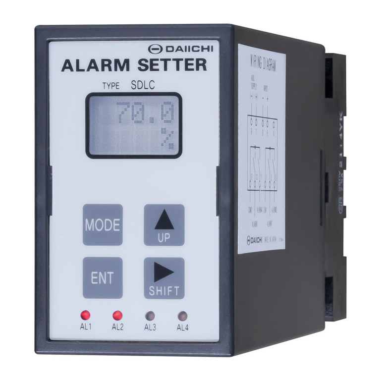
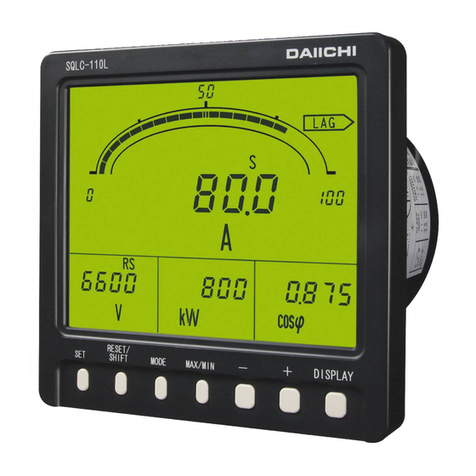
Daiichi Electronics SQLC-72L User manual

SQLC-216-212
INSTRUCTION MANUAL
(DETAILED VERSION)
POWER LINE SUPER MULTI-METER
SQLC-72L

SQLC-216-212
1
Contents
Introduction ・・・・・・・・・・・・・・・・・・・・・・・・・・・・・・・・・・・・・・・・・・・・・・・・・・・・・・・・・・・・・・・・・・・・・・・ 2
Safety Precaution ・・・・・・・・・・・・・・・・・・・・・・・・・・・・・・・・・・・・・・・・・・・・・・・・・・・・・・・・・・・・・・・・・・ 2
Composition of type ・・・・・・・・・・・・・・・・・・・・・・・・・・・・・・・・・・・・・・・・・・・・・・・・・・・・・・・・・・・・・・・ 3
1. Product outline ・・・・・・・・・・・・・・・・・・・・・・・・・・・・・・・・・・・・・・・・・・・・・・・・・・・・・・・・・・・・・・・・・・ 4
1.1 Features of product ・・・・・・・・・・・・・・・・・・・・・・・・・・・・・・・・・・・・・・・・・・・・・・・・・・・・・・・・・・ 4
1.2 Part names ・・・・・・・・・・・・・・・・・・・・・・・・・・・・・・・・・・・・・・・・・・・・・・・・・・・・・・・・・・・・・・・・・・・ 4
1.3 Bundled items ・・・・・・・・・・・・・・・・・・・・・・・・・・・・・・・・・・・・・・・・・・・・・・・・・・・・・・・・・・・・・・・・ 4
2. Dimensions ・・・・・・・・・・・・・・・・・・・・・・・・・・・・・・・・・・・・・・・・・・・・・・・・・・・・・・・・・・・・・・・・・・・・・・・ 4
2.1 SQLC-72L ・・・・・・・・・・・・・・・・・・・・・・・・・・・・・・・・・・・・・・・・・・・・・・・・・・・・・・・・・・・・・・・・・・・・・ 4
2.2 Current sensor (Option) ・・・・・・・・・・・・・・・・・・・・・・・・・・・・・・・・・・・・・・・・・・・・・・・・・・・・・・ 5
2.3 Zero-phase current transformer ZCT (Option) ・・・・・・・・・・・・・・・・・・・・・・・・・・・・・・・・・・ 6
3. Installation instructions ・・・・・・・・・・・・・・・・・・・・・・・・・・・・・・・・・・・・・・・・・・・・・・・・・・・・・・・ 7
4. Connection ・・・・・・・・・・・・・・・・・・・・・・・・・・・・・・・・・・・・・・・・・・・・・・・・・・・・・・・・・・・・・・・・・・・・・・・ 10
4.1 Low-voltage circuit ・・・・・・・・・・・・・・・・・・・・・・・・・・・・・・・・・・・・・・・・・・・・・・・・・・・・・・・・・・ 10
4.2 High-voltage circuit ・・・・・・・・・・・・・・・・・・・・・・・・・・・・・・・・・・・・・・・・・・・・・・・・・・・・・・・・・ 11
5. Operation and Screen ・・・・・・・・・・・・・・・・・・・・・・・・・・・・・・・・・・・・・・・・・・・・・・・・・・・・・・・・・・・・ 11
6. Display mode ・・・・・・・・・・・・・・・・・・・・・・・・・・・・・・・・・・・・・・・・・・・・・・・・・・・・・・・・・・・・・・・・・・・・・・ 12
6.1 Measurement display ・・・・・・・・・・・・・・・・・・・・・・・・・・・・・・・・・・・・・・・・・・・・・・・・・・・・・・・・・・ 12
6.2 Instant measurement display mode ・・・・・・・・・・・・・・・・・・・・・・・・・・・・・・・・・・・・・・・・・・・・・ 13
6.3 Maximum value / Minimum value display mode ・・・・・・・・・・・・・・・・・・・・・・・・・・・・・・・・・・・ 14
6.4 Reset ・・・・・・・・・・・・・・・・・・・・・・・・・・・・・・・・・・・・・・・・・・・・・・・・・・・・・・・・・・・・・・・・・・・・・・・・ 14
6.5 Setting value display mode ・・・・・・・・・・・・・・・・・・・・・・・・・・・・・・・・・・・・・・・・・・・・・・・・・・・ 15
7. Setting ・・・・・・・・・・・・・・・・・・・・・・・・・・・・・・・・・・・・・・・・・・・・・・・・・・・・・・・・・・・・・・・・・・・・・・・・・・ 16
7.1 Setting mode 1 ・・・・・・・・・・・・・・・・・・・・・・・・・・・・・・・・・・・・・・・・・・・・・・・・・・・・・・・・・・・・・・・ 16
7.2 Setting mode 2 ・・・・・・・・・・・・・・・・・・・・・・・・・・・・・・・・・・・・・・・・・・・・・・・・・・・・・・・・・・・・・・・ 20
8. Test mode ・・・・・・・・・・・・・・・・・・・・・・・・・・・・・・・・・・・・・・・・・・・・・・・・・・・・・・・・・・・・・・・・・・・・・・・ 26
9. Specifications ・・・・・・・・・・・・・・・・・・・・・・・・・・・・・・・・・・・・・・・・・・・・・・・・・・・・・・・・・・・・・・・・・・ 28
10. Description of functions ・・・・・・・・・・・・・・・・・・・・・・・・・・・・・・・・・・・・・・・・・・・・・・・・・・・・・・・・ 35
10.1 Contact output ・・・・・・・・・・・・・・・・・・・・・・・・・・・・・・・・・・・・・・・・・・・・・・・・・・・・・・・・・・・・・・ 35
10.2 Inrush current mask function ・・・・・・・・・・・・・・・・・・・・・・・・・・・・・・・・・・・・・・・・・・・・・・・・・・ 35
10.3 Power flow measurement ・・・・・・・・・・・・・・・・・・・・・・・・・・・・・・・・・・・・・・・・・・・・・・・・・・・・・・ 35
11. Multi-Meter Configuration Software(SQLC-CS-01)・・・・・・・・・・・・・・・・・・・・・・・・・・・・・・・・・ 36
11.1 Outline ・・・・・・・・・・・・・・・・・・・・・・・・・・・・・・・・・・・・・・・・・・・・・・・・・・・・・・・・・・・・・・・・・・・・・ 36
11.2 Hardware requirements ・・・・・・・・・・・・・・・・・・・・・・・・・・・・・・・・・・・・・・・・・・・・・・・・・・・・・・・ 36
11.3 System configuration ・・・・・・・・・・・・・・・・・・・・・・・・・・・・・・・・・・・・・・・・・・・・・・・・・・・・・・・・ 36
12. Troubleshooting ・・・・・・・・・・・・・・・・・・・・・・・・・・・・・・・・・・・・・・・・・・・・・・・・・・・・・・・・・・・・・・・・ 37
Appendix table 1...3

SQLC-216-212
2
Introduction
Thank you for purchase of DAIICHI product.
Please read this instruction manual carefully before use.
Keep this manual for future reference.
Please contact with us in case this manual is lost or damaged.
Safety Precaution
■ Usage environment and conditions
Don't use this product in the following conditions.
① Locations beyond the ambient temperature range (-10...+55 ℃) and humidity range (5...90 % RH).
② Locations with excessive corrosive gas (SO2 / H2S / etc.)
③ Locations with excessive dust.
④ Locations with excessive vibration or shocks.
⑤ Locations with excessive exogenous noise.
⑥ Altitude over 2000 m.
⑦ When measure the following inverter output directly, error will becomes large.
Cycle control, SCR phase angle control, PWM inverter.
■ Outdoor use conditions.
① These products are not a dustproof, waterproof, and splash proof construction.
Please avoid the place with much dust. Please do not install in the place directly exposed to the rain
and water droplets. (IP code:IP40)
② Please do not install in the place directly exposed to the sun even through the glass. Discoloration and
degradation of a name plate, and deformation of the box by the surface temperature rise may caused.
③ Product life may shorten when the daily average temperature exceeds 40 ℃.
■ Mounting and wiring
Please refer to this instruction manual for installation and the wiring.
Please refer to connection diagram for the wiring. An improper connection may cause troubles.
Hot line work is prohibited. There is a risk of explosion by electric shock, device malfunction, burning,
fire, or gas.
Please use an electrical wire size suitable with the rated current.
Use unsuitable size electric wire, which may lead to a fire.
Please carry out coating removal of a covering electric wire by reasonable length. If covering removal
is too long, there is a possibility of short-circuiting with the next electric wire. Moreover, if covering
removal of an electric wire is too short, a mating defect and poor contact may be caused.
Be careful of the short circuit by the exposure of conductor.
Please use it combining the current sensor of this product and exclusive use.
Please use a current sensor within input rated range.
Since a current sensor (exclusive use) is only for low-voltage circuits, it cannot be used for a high-voltage
circuit. Connecting with a high-voltage circuit is dangerous.
When using with a circuit of 600 A or more, please connect the current sensor of the 5 A rated the (CTF-5A)
on the secondary side of the instrument for the current transformer (secondary 5 A).
Primary cable to connect to the current sensor, please use the penetrable insulated wire.
Please do not use non-insulated wire and conductor (bus bar, etc.).
As for the core division surface of a current sensor, characteristics worsen by adhesion of dust or accrual
of rust. Be careful not to attach dirt to a core division surface. When dirty, please clean with a dry cloth.
As for the core division surface of a current sensor, characteristics worsen by adhesion of dust or accrual
of rust. Be careful not to attach dirt to a core division surface.
When dirty, please clean with a dry cloth.
Please do not continuously energized the secondary side of the current sensor in an open state.
However, this product has a built-in protection circuit of the secondary terminal open.
There is no problem in the open in the wiring construction period.
The current sensor has polarity. Please note the time of installation.

SQLC-216-212
3
■ Preparation
This product must be set before use. Please read this manual and make the setting correctly.
If you make a mistake on the setting it does not operate correctly.
■ Maintenance and inspection
① Inspection during energization is dangerous.
② No replacement in periodic inspection.
③ Please wipe off lightly with the dry soft cloth.
Please do not use the organic solvent, chemicals, cleaners, etc., such as an alcohol, for cleaning.
■ Storage
If you want to long-term storage, please avoid the following environment.
Locations beyond the ambient temperature range and humidity range. -25...+70 ℃, 5...90 % RH
Daily average temperature more than 40 ℃.
Location corresponding to the usage environment and use conditions (②...④).
■ Countermeasures against troubles
If this product breaks down within the warranty period, it will be repairs by DAIICHI Electronics.
■ Disposal
Please dispose of this product as industrial waste (noncombustible).
Mercury parts and a nickel-cadmium battery are not used for this product.
■ Warranty period
The warranty period of the product is one year after the date of delivery.
■ Warranty scope
In the state of the normal use of product-specification within the range according to this instruction manual,
the trouble within the warranty period performs exchange or repair gratuitously.
However, if it corresponds to the next, it does not warrant.
① If it breaks down when converted or repaired except our company.
② If it breaks down by use out of specification range.
③ If the cause of trouble is based on cause other than this product.
④ Transportation, movement, damage by falling, and trouble.
⑤ Other, natural disasters, disasters, etc. In the case where the supplier side (Company and agent) is
not responsible.
This warranty is a guarantee for the delivered product. Cannot warrant the damage induced by trouble of
this product.
■ Replacement cycle of the product
We recommend updating the product for 10 years as a rough standard.
■ Change of instruction manual written contents.
This instruction manual changes written contents without a notice by product improvement etc.
Composition of type
Type Specification code
SQLC-72L-
① Hardware model ② Auxiliary supply ③ Control input, Communication output,
Contact output
A Hardware model A 1 85...264 V AC
80...143 V DC 1
Control input:DI ×1
Communication output:MODBUS RTU
Contact output:DO ×2
2 20...56 V DC

SQLC-216-212
4
1 Product outline
1.1 Features of product
Small Multi-meter, DIN 72 mm square size
Input circuit is a 3 phase 3 wire, 1 phase 3 wire, 1 phase 2 wire, 3 phase 4 wire shared.
400 V direct connection is possible (110 V / 220 V / 440 V shared)
Compliant for international standards [IEC 60688:2012 (Transducer), IEC 62053:2003 (Electricity
metering equipment), CE marking]
Equipped with a liquid crystal panel with a wide viewing angle.
Equipped with a high visibility high-intensity white backlight.
Wiring can be confirmed by the test function.
Screw-less spring-type terminal block the adoption. Wiring man-hours can be reduced.
RS485 Communication output(MODBUS RTU), Alarm output, Pulse output can be output simultaneously.
1.2 Part names
1.3 Bundled items
① Instruction Manual (Instruction・Operation) ・・・・・・・・・ 1
② Attachment tool ・・・・・・・・・・・・・・・・・・・・・・・・・・・・・・・・・・・・・ 2
③ Termination resister for communication (100 Ω) ・・・・・ 1
2 Dimensions
2.1 SQLC-72L
■ Operation switch
LCD
Digital display
Unit
display
Auxiliary supply, Ground terminal
Voltage input terminal
Current sensor input, ZCT input, Communication output,
Control input, Contact output terminal
Attachment tool
Attachment tool
-/+
Switch
SET
Switch
RESET
Switch
DISPLAY
Switch

SQLC-216-212
5
2.2 Current sensor (option):Made by MULTI MEASURING INSTRUMENTS Co., Ltd.
5A(CTF-5A)
7.9
25.3
42
41.3
10
38.5
33
50A(CTF-50A)
25.5
42
9.5
10
28.6
23
48
100A(CTF-100A)
14.5
46
30.5
55
16
37.5
29.5
200A(CTF-200A)
24
52.5
35.5
76
24
55.5
45
400A(CTF-400A)
35.5
18.5
35.5
53
94
37
73
62.5
600A(CTF-600A)
35.5
18.5
35.5
53
37
94
73
62.5

SQLC-216-212
6
2.3 Zero-phase current transformer ZCT (option) : Made by OMRON Corporation
50A(OTG-LA21)
(Mounting pitch)
11
13.5
27 28
68.5
6
74
8.5
50
4.1 64
9.3
1.8
Terminal cover
20
17
φ21
5.9
1.7
4.7
5.2
100A(OTG-LA30)
φ30
63
6
57
86
34.5
81.5
33.5 13.5
8.5
50
54
4.1
1.8
9.3
(Mounting pitch)
76
1.7
20
Terminal cover
17
5.9
5.2
2.2
200A(OTG-LA42)
Terminal cover
25
17
107
φ42
(Mounting pitch)
97
109
88
9.3
11
5.2
400A(OTG-LA68)
(Mounting pitch)
143
118
φ68
136
131 31
Terminal cover
17
11
9.3
6.1
600A(OTG-LA82)
Terminal cover
φ82
158
160 (Mounting pitch)
172
138
11
9.3
33
28
17
6.2
100A for outdoor(OTG-LA30W)
62
Lead wire color
No polarity
:White, Black
φ30
5.5
24 73.5
3.5
20
φ5.5
(Mounting pitch)
84
68
2
10.5
500
42.5
5
(JIS C 3306)
1.25mm VCTFK
2

SQLC-216-212
7
● CT inside diameter and wiring length of current sensor
Primary
current Type CT inside
diameter
Wiring length
(Max.)
5 A CTF-5A 10 mm 10 m
50 A CTF-50A 10 mm
50 m
100 A CTF-100A 16 mm
200 A CTF-200A 24 mm
400 A CTF-400A 37 mm
600 A CTF-600A 37 mm
(M3 screw)
Attaching portion
(to right and left)
Attachment tool
phillips screwdriver.
Tightened with a
Tightening torque:0.1N・m
3 Installation instructions
■ Panel cutout dimensions
98 or more
68+0.7
-0
98 or more
Panel cutout
+0.7
-0
68
■ Mounting position
Since the LCD contrast is changed in accordance
with the monitoring angle, please be installed at
the optimal angle.
75°
75°
(Side view) (Top view)
75° 75°
■ Installation
Insert from the front panel cut hole.
Install as shown in the figure below.
■ Connection of current sensor
① Remove the fixing hooks, and open the movable core.
Please check the mounting direction of the current sensor. (Symbol:Power supply side K, Load side L)
Pass the wirees in the center of the current sensor.
② Make sure that there is no dust on the core division surface.
Until the sound of the fixing hook is, please close the movable core.
③ To secure the current sensor to the wire in the cable ties.
①
Movable core Terminal cover
Core division
conductor
(cable)
Primary
surface
Fixing hook
②
Close the
fixing hook
③
Aux.supply
Fixing hole
(4mm×2mm)
Cable ties
(K)
side
Primary
(cable)
Load side
conductor
Fixing hole
(4mm×2mm)
Cable ties
(L)
● Solderless terminal to be used in the
secondary terminal of the current sensor,
please use the Solderless terminal of the
specified.
Solderless terminal for M3 screw (Without
insulation sleeve)
Tightening torque:0.5...0.6 N・m

SQLC-216-212
8
■ Connection method
(1) Applicable wire
Terminal is a screw-less spring-type terminal. Fit wire size, please refer to the table below.
Terminal Wire
Applicable wire
Single
wire
Flexible
stranded
wire
Stranded wire,
rod terminal
(Ferrule with
insulating
collar)
Stranded wire,
rod terminal
(Ferrule without
insulating
collar)
Two stranded wire,
rod terminal
(Twin ferrule with
insulating collar)
Delamination
of wire
Voltage input,
Auxiliary supply,
Ground
Cross-sectional
area 0.08 ... 2.5 mm2 0.25 ... 1.5 mm2 0.5 mm2×2
5 ... 6 mm
AWG 28 ... 12 24 ... 16 22
Current sensor, ZCT,
Communication output,
Control input,
Contact output
Cross-sectional
area 0.08 ... 2.5 mm2 0.25 ... 1.5 mm2 0.5 mm2×2
AWG 28 ... 12 24 ... 16 22
Flexible stranded wire Single wire
Stranded wire, rod terminal Stranded wire, rod terminal Two stranded wire, rod terminal
(Ferrule with insulating collar) (Ferrule without insulating collar) (Twin ferrule with insulating collar)
In case of flexible stranded wire, please be careful not to loosen
the wire. There is a rod terminal as a preventive measure.
Rod terminal of recommendation, please refer to the following.
Also, please use a dedicated crimping tool to rod terminal.
Rod terminal:WAGO, Ferrule with insulating collar /
Ferrule without insulating collar, 216 series
Crimping tool:WAGO, Ferrule crimping tool 206-204 (Applicable wire:0.25 mm
2
to 4 mm
2
)
Please use a rod terminal that matches the wire size.
The tip of the wire, please cut the length of the rod terminal (or about 0.5 mm long).
After the rod terminal crimping, please check the appearance.
◯ × Exposure of conductor × Damage to the side × Wire peeling shortage
Twin ferrule with insulating collar
can crimp more two standard wires at
the same time.
Please use in the case of two wires to
daisy chain, such as one terminal.
0 ... 0.5 mm
Pressure bonding
Exposure of conductor
Damage
Insufficient length of
the wire

SQLC-216-212
9
Screwdriver
insertion slot Wire insertion slot
Wire insertion slot
Current sensor, ZCT, Communication output,
Control input, Contact output
(2) Connection method
① Stripping 5-6 mm a coating of the tip of the wire. Or, crimping the rod terminal.
The screwdriver of the flat-blade screwdriver cutting edge (3.5 mm × 0.5 mm)
② Insert the screwdriver to screwdriver insertion slot, open the spring.
③ To insert the wire to the wire insertion slot.
④ Pull out the screwdriver, close the spring.
【Recommended screwdriver】Cutting edge 3.5 mm×0.5 mm
WAGO made screwdriver:210-720, 210-657, 210-658, 210-120J, 210-350/01, 210-258J
① 5 ... 6 mm Without of loosened and twisting and bending
②
③
④
【Screwdriver and wire insertion slot】
【Upper position terminal】 【Lower position terminal】
Insert the
screwdriver to
open the spring
Screw driver
Auxiliary supply, Ground Voltage input

SQLC-216-212
10
4 Connection
4.1 Low-voltage circuit (1)(2)
■ 3 phase 3 wire(2VT2CT) ■ 3 phase 3 wire(2VT3CT)
L1
L2
L3
AUX.SUPPLY
CONTACT OUTPUT 1
CONTACT OUTPUT 2
CONTROL INPUT
24681012141618202224
( )
-
( )
~
+
~
25 26 27 28 29 30 31
MODBUS
(INPUT)
(COM)
(+)
(-)
(+)
(-)
1357911
( )
3
LOAD
(CURRENT SENSOR)
K
1513 17 2119 23
L
ZCT
CT
K
L
31
(CURRENT SENSOR)
K
L
2 4 6 8 10121416182022
( )
( )
AUX.SUPPLY -
~
+
~
25 26 27 28 29 30
(+)
(-)
(+)
(-)
(INPUT)
(COM)
CONTACT OUTPUT 1
CONTACT OUTPUT 2
CONTROL INPUT
MODBUS
( )
31 5 7 9
3
LOAD
1311 15 1917 21
ZCT
CT
L
L
K
24
23
K
L2
L3
L1
■ 1 phase 3 wire ■ 1 phase 2 wire
L3
L1
AUX.SUPPLY
CONTACT OUTPUT 1
CONTACT OUTPUT 2
CONTROL INPUT
MODBUS
(-)
-
( )
~
(INPUT)
( )
+
~
(COM)
25 26 27
246
135
10812
7 9 11
(+)
(+)
(-)
LOAD
( )
3
28 29 30 31
1614 18
15
13 17
2220 24
2119 23
K
(CURRENT SENSOR)
L
ZCT
CT
K
LN
31
(CURRENT SENSOR)
(+)
(-)
(+)
(-)
(INPUT)
(COM)
( )
( )
CONTACT OUTPUT 1
CONTROL INPUT
AUX.SUPPLY -
~
+
~
CONTACT OUTPUT 2
10
25 26 27
3
4
2
1
6 8
579
28 29 30
1412 16
13
11 15
2018 22
1917 21
MODBUS
( )
LOAD
3
ZCT CT
L K
24
23
L2
L1
■ 3 phase 4 wire(3VT3CT)
LK
AUX.SUPPLY
CONTACT OUTPUT 1
CONTACT OUTPUT 2
CONTROL INPUT
MODBUS
+
( )
-
( )
~
~
(INPUT)
(-)
(COM)
(+)
(-)
(+)
25 26
2
1
46
35
27
108
7
12
911
LOAD
( )
3
K
28 29
15
16
14
13
18
17
30 31
21
22
20
19
24
23
L
(CURRENT SENSOR)
L
ZCT
CT
K
L2
N
L3
L1
Maximum rated voltage by wiring type
Wiring type
3 phase 4 wire 3 phase 3 wire
(Ground)
3 phase 3 wire
(Ungrounded)
1 phase 2 wire
(Ground)
1 phase 2 wire
(Ungrounded) 1 phase 3 wire
Maximum rated
voltage
277V(L-N)
480V(L-L) 220V(L-L) 480V(L-L) 220V(L-L) 480V(L-L) 220V(L-N)
440V(L-L)
Wiring of communication output (3)
【Daisy chain (line type)】【Termination unit】
7 9 11 13
8 101214
SHIELD SG - +
SHIELD SG - +
791113
8 101214
SHIELD SG - +
TERMINATION RESISTOR

SQLC-216-212
11
4.2 High-voltage circuit (4)
■ The use example of high-voltage circuit, 3 phase 3 wire(2VT2CT)
AUX.SUPPLY
CONTACT OUTPUT 1
CONTACT OUTPUT 2
CONTROL INPUT
-
~
( )
~
( )
+
25 26 27 28 29 30 31
SENSOR
CURRENT
MODBUS
(INPUT)
(COM)
(-)
(-)
(+)
(+)
2
1
46
35
108
7
12
911
LOAD
( )
3
K
KL
15
1614
13
18
17 21
2220
19
24
23
K L
L
L
CTK
UU V
L1
VT
V
L3
L2
Note(1) In case of the low-voltage circuit (600 V or less), the secondary grounding of VT / CT is not required.
In case of the 110V / 220V / 440V direct input, VT is not required.
Note(2) When using with a circuit of 600 A or more, please connect the current sensor of the 5 A rated the
(CTF-5A) on the secondary side of the instrument for the current transformer (secondary 5 A).
Note(3) Communication output terminal (7-8, 9-10, 11-12 ,13-14) are connected internally respectively.
In case of the daisy chain, please connect in accordance with the 10 pages figure.
Termination resistor for the communication output, please use at the end of equipment.
Please connect the termination resistor between the terminals (+)(-) of communication output.
Note(4) In case of the high-voltage circuit, using instrument transformers (VT), and instrument for the
current transformer (CT) of secondary rated 5 A, please ground the secondary side.
Current sensor in the secondary of the current transformer, please connect the current sensor (CTF-5A)
of 5A rating.
5 Operation and Screen
Current sensor connection diagram of circuit
of 600A or more and high-voltage circuit. (2)
Current transformer of
secondary output 5A.
Current sensor
(5A rating:CTF-5A)
Setting
number
Setting
number
For more information on each mode,
please refer to each page.
N
ew
setting
Current
setting
New
setting
Current
setting
Test
number
Setting mode 2
SET
3 seconds
Start screen
Display mode
(Measurement
display)
Display for 2
seconds
DISPLAY
POWER ON
Not operated for 10 minutes
16 pages
12 pages
SET and RESET
3 seconds
SET and DISPLAY
3 seconds
DISPLAY
DISPLAY
20 pages
26 pages
Setting mode 1
Test mode

SQLC-216-212
12
Alarm contact status display
Upper and lower alarm display Communication status display
Operation effective display Unit display
Phase / line display
Measurement display
(Main-monitor)
Measurement display
(Sub-monitor)
6 Display mode
6.1 Measurement display
Switch Operation
SET Switching of operation screen
-/+ Switching of measuring element.
RESET
(Pressing for more than 1 second)
Reset of each alarm (Instant measurement display mode)
Reset of maximum value / minimum value (Maximum / Minimum value display
mode)
DISPLAY Switching of measurement display. Phase / Line / Average value (AVG)
SET
(Pressing for more than 3 second) Switch to setting mode 1
SET and RESET
(Pressing for more than 3 second) Switch to setting mode 2
SET and DISPLAY
(Pressing for more than 3 second) Switch to test mode
About the element symbol
U Voltage
I Current
Id Demand current
P Active power
Pd Demand active power
Q Reactive power
S Apparent power
PF Power factor
f Frequency
Io Leakage current
Wh Active energy
varh Reactive energy
Display mode
(Measurement display)
-/+
SET
DISPLAY
RESET
1 second
Switching of
measuring element
Switching of phase
(line), average
value
Switching of
operation screen
Maximum value /
Minimum vale
reset
Alarm reset
Instant measurement
display mode
SET and +
RESET
1 second
Maximum value /
Minimum value display

SQLC-216-212
13
6.2 Instant measurement display mode
(1) Switching of main-monitor display element
Press the【SET】 switch, to display the【▲】 (operation effective display).
Then by pressing the【+】【-】 switch the display elements of the main-monitor.
【 Voltage (U) display 】 【 Current (I) display 】 【 Demand current (Id) display 】
Measuring element is switched in the following order.
U ⇔ I ⇔ Id ⇔ P ⇔ Pd ⇔ Q ⇔ S ⇔ PF ⇔ f ⇔ Io ⇔ OFF
(2) Switching of the sub-monitor display element
Press the【SET】 switch, to display the【▼】 (operation effective display).
Then by pressing the【+】【-】 switch the display elements of the sub-monitor.
【 Active power (P) display 】 【Reactive power (Q) display】 【Receiving active energy (Wh) display】
Measuring element is switched in the following order.
P ⇔ Q ⇔ Wh ⇔ -Wh ⇔ varh(LAG) ⇔ varh(LEAD) ⇔ -varh(LAG) ⇔ -varh(LEAD) ⇔ OFF
(3) Switching of phase (line) / average value (AVG) display
By pressing the【DISPLAY】 switch the phase (line) display of the main-monitor.
Measuring element is switched in the following order.
Measurement element (1,2,3,N:Phase, Σ:Total)
3 phase 3 wire 1 phase 3 wire 3 phase 4 wire
Voltage U(L1-2) ⇔ U(L2-3) ⇔
U(L3-1) ⇔ U(L-L AVG)
U(L1-N) ⇔ U(L3-N) ⇔
U(L1-3) ⇔ U(L-N AVG)
U(L1-N)
⇔
U(L2-N)
⇔
U(L3-N)
⇔
U(L1-2)
⇔
U(L2-3)
⇔ U(L3-1)
⇔
U(L-N AVG)
⇔
U(L-L AVG)
Current,
Demand current
I(L1) ⇔ I(L2) ⇔
I(L3) ⇔ I(AVG)
I(L1) ⇔ I(L3) ⇔
I(N) ⇔ I(AVG) I(L1) ⇔ I(L2) ⇔ I(L3) ⇔ I(N) ⇔ I(AVG)
Active power,
Demand active power ― ― P(Σ) ⇔ P(L1) ⇔ P(L2) ⇔ P(L3)
Reactive power ― ― Q(Σ) ⇔ Q(L1) ⇔ Q(L2) ⇔ Q(L3)
Apparent power ― ― S(Σ) ⇔ S(L1) ⇔ S(L2) ⇔ S(L3)
Power factor ― ― PF(Σ) ⇔ PF(L1) ⇔ PF(L2) ⇔ PF(L3)
Display of phase / line, can be switched in the settings.
Setting L123N RSTN UVWN
Phase, line
display
L1 R U
L2 S V
L3 T W
N N N
+
-
+
-
+
-
+
-
DISPLAY DISPLAY

SQLC-216-212
14
6.3 Maximum value / Minimum value display mode
Pressing the【SET】 and【+】 at instant measurement display mode, the switches to the maximum value display mode.
〔In maximum value display mode, to display the "MAX." 〕
Pressing the【SET】 and【+】 at maximum value display mode, the switches to the minimum value display mode.
〔In minimum value display mode, to display the "MIN." 〕
The maximum value/ minimum value display mode, will be switched to the measuring element pressing the【+】
【-】 switch. And, pressing the【DISPLAY】 switch the phase (line).
【Instant measurement display mode】 【Maximum value display mode】 【Minimum value display mode】
6.4 Reset
(1) Alarm reset
If the contact output is using the alarm output "HoLd (manual return)", press the【RESET】 switch for more
than 1 second at the instant measurement display mode, the alarm output is reset.
When set to "Auto (automatic return)" the alarm reset method, output is off in accordance with the alarm reset.
Therefore, this operation is not necessary.
<Note> When the carry out this operation in the maximum / minimum measurement display mode, the maximum value
/ minimum value of measurement element in display is reset. Always instant measurement display mode,
please carry out this operation.
Instant measurement display mode Reset completion
(2) Maximum value / Minimum value reset
Resets the maximum value and the minimum value of the various measurement values.
Reset method has the following two types. Individually reset of measurement element.
Collectively reset all of the maximum value / minimum value.
a) Individually reset
Resets the maximum and minimum values of a particular measurement element.
This operation does not reset the other maximum value and minimum value.
① Displays the measurement element that want to reset.
② Press the【RESET】 for more than 1 second.
<Note> When the carry out this operation in the instant measurement display mode, the alarm output is reset.
From to display the measurement elements of the maximum (or minimum value) to be reset, please carry
out this operation.
Maximum value display mode Reset completion
SET and + SET and +
RESET
1 second
Alarm detection (Hold)
RESET
1 second
Maximum
measurement
display

SQLC-216-212
15
b) Reset collectively
Resets the maximum and minimum values of all measurement element.
Can be operated in the same way in the control input by the setting.
① At the maximum / minimum measurement display mode, press the【RESET】 and【+】 for more than 1 second.
Maximum value display mode Reset completion
6.5 Setting value display mode
From the instant measurement display mode, press【SET】 and【-】 to enter setting value display mode.
Pressing the
【+】【-】
switch in the setting value display mode, switching the voltage setting and current
setting.
If you press the【DISPLAY】 switch or do not operate any switches for over 10 seconds, the instant measurement
display mode is restored.
【Instant measurement display mode】 【Voltage setting】 【Current setting】
Main-monitor (upper side)
:Primary rated current
Sub-monitor (lower side)
:Current sensor rating
Main-monitor (upper side)
:Primary rated voltage
Sub-monitor (lower side)
:Secondary rated voltage
or not operate
for over 10
seconds
+ −
で
SET and -
DISPLAY
RESET and +
1 second
Maximum
measurement
display

SQLC-216-212
16
7 Setting
7.1 Setting mode 1
(Contact output structure, Various detection settings, Inrush current mask, Backlight action)
(1) Setting mode 1 flowchart
Display mode
DISPLAY
SET
3 seconds
Setting mode 1
Contact
composition
111
Contact output 1
function
RESET
112
Contact output 1
return method
RESET
113
Contact output 1
delay time
RESET
114
Contact output 2
function
RESET
115
Contact output 2
return method
RESET
116
Contact output 2
delay time
RESET
and +
RESET
and -
RESET
and +
RESET
and -
Current detection
121
Current, upper 1
RESET
122
Current, upper 1
output
RESET
123
Current, upper 2
RESET
124
Current, upper 2
output
RESET
125
Current, lower
RESET
126
Current, lower
output
RESET
127
0A detection
exclude
Demand current
detection
131
Demand current,
interval
RESET
132
Demand current,
upper 1
RESET
133
Demand current,
upper 1 output
RESET
134
Demand current,
upper 2
RESET
135
Demand current,
upper 2 output
RESET
and +
RESET
and -
Demand active
power detection
141
Demand power,
interval
RESET
142
Demand power,
upper 1
RESET
143
Demand power,
upper 1 output
RESET
144
Demand power,
upper 2
RESET
145
Demand power,
upper 2 output
RESET
and +
RESET
and -
Leakage current
detection
151 Leakage
sensitivity
current 1
RESET
152 Leakage
sensitivity
current 1 output
RESET
153 Leakage
sensitivity
current 2
RESET
154 Leakage
sensitivity
current 2 output
RESET
155
Use ZCT
selection
RESET
and +
RESET
and -
Backlight
171
Backlight action
RESET
172
Backlight
luminance
RESET
and -
RESET
and +
Inrush current
mask
161
Inrush current
mask level
RESET
162
Inrush current
mask time

SQLC-216-212
17
(2) Contact composition
No. Setting item Contents of setting
111
114
Contact output 1
function
Contact output 2
function
Set function of contact output 1 and contact output 2.
Setting value is selecting in the【+】【-】.
To update the setting value in the【SET】.
112 (5)
115 (5)
Contact output 1
return method
Contact output 2
return method
Set return method of contact
output 1 and contact output 2.
Setting value is selecting in
the【+】【-】.
To update the setting value in the【SET】.
113 (5)
116 (5)
Contact output 1
delay time
Contact output 2
delay time
Set contact delay time of contact
output 1 and contact output 2.
Setting value is selecting in the
【+】【-】. To update the setting value in the【SET】.
(3) Current detection
No. Setting item Contents of setting
121
123
Current, upper 1
Current, upper 2
Set detection value of the
upper detection 1 and the
upper detection 2 of
current.
Setting value is selecting in the【+】【-】.
To update the setting value in the【SET】.
122 (5)
124 (5)
126 (5)
Current, upper 1
output
Current, upper 2
output
Current, lower
output
Set output allocation of
upper detection 1 and upper
detection 2, and lower
detection.
Setting value is selecting
in the 【+】【-】.
To update the setting value in the【SET】.
125 Current, lower Set detection value of the
lower detection of current.
Setting value is selecting
in the【+】【-】.
To update the setting value in the【SET】.
127 0A detection
exclude
Set exclude of the lower
detection of current.
[At the time of no input
(0A)]
Setting value is selecting in the【+】【-】.
To update the setting value in the【SET】.
Note(5) This setting is [111 contact 1 function], [114 contact 2 function] is valid at the time of the alarm
output.
Detection value
1...200% (1% step), OFF
(Rated current at 100%, 1% step)
Output
Contact output 1 o.1
Contact output 2 o.2
Contact output 1, 2 o.1-2
OFF oFF
Detection value
OFF, 1...200% (1% step)
(Rated current at 100%, 1% step)
Detection exclude
Exclude detection on
Not exclude detection oFF
Delay time
0...300 s (1 s step)
Return method
Auto return Auto
Manual return HoLd
Function of contact output
OFF oFF
Pulse output PLS
Alarm output ALm
New setting
Setting No.
Current setting

SQLC-216-212
18
(4) Demand current detection
No. Setting item Contents of setting
131 Demand current,
interval
Set interval of demand current measurement.
Setting value is selecting in the【+】【-】.
To update the setting value in the【SET】.
132
134
Demand current,
upper 1
Demand current,
upper 2
Set detection value of the
upper detection 1 and the
upper detection 2 of
demand current.
Setting value is selecting in the【+】【-】.
To update the setting value in the【SET】.
133 (6)
135 (6)
Demand current,
upper 1 output
Demand current,
upper 2 output
Set output allocation of
upper detection 1 and
upper detection 2 of
demand current.
Setting value is selecting
in the【+】【-】. To update the setting value in the【SET】.
(5) Demand power detection
No. Setting item Contents of setting
141 Demand power,
interval
Set interval of demand power measurement.
Setting value is selecting in the【+】【-】.
To update the setting value in the【SET】.
142
144
Demand power,
upper 1
Demand power,
upper 2
Set detection value of the
upper detection 1 and
the upper detection 2 of
demand power.
Setting value is selecting in the【+】【-】.
To update the setting value in the【SET】.
143 (6)
145 (6)
Demand power,
upper 1 output
Demand power,
upper 2 output
Set output allocation of
upper detection 1 and
upper detection 2 of
demand power.
Setting value is selecting
in the 【+】【-】.
To update the setting value in the【SET】.
Note(6) This setting is [111 contact 1 function], [114 contact 2 function] is valid at the time of the alarm
output.
Interval
0 s 20 s 50 s 3 min 6 min 9 min 20 min
5 s 30 s 1 min 4 min 7 min 10 min 25 min
10 s 40 s 2 min 5 min 8 min 15 min 30 min
Detection value
5...200% (1% step), OFF
(Rated current at 100%, 1% step)
Output
Contact output 1 o.1
Contact output 2 o.2
Contact output 1, 2 o.1-2
OFF oFF
Detection value
5...200% (1% step), OFF
(Rated active power at 100%, 1% step)
Interval
0 s 20 s 50 s 3 min 6 min 9 min 20 min
5 s 30 s 1 min 4 min 7 min 10 min 25 min
10 s 40 s 2 min 5 min 8 min 15 min 30 min
Output
Contact output 1 o.1
Contact output 2 o.2
Contact output 1, 2 o.1-2
OFF oFF

SQLC-216-212
19
(6) Leakage current detection
No. Setting item Contents of setting
151
153
Leakage
sensitivity
current 1
Leakage
sensitivity
current 2
Set sensitivity current 1 and
sensitivity current 2 of the
leakage current detection.
Setting value is selecting in the
【+】【-】. To update the setting
value in the【SET】.
152 (7)
154 (7)
Leakage
sensitivity
current 1 output
Leakage
sensitivity
current 2 output
Set output allocation of
detection 1 and detection
2 of leakage sensitivity
current.
Setting value is selecting
in the 【+】【-】.
To update the setting value in the【SET】.
155 Use ZCT
selection
Set ZCT to use for leakage current measurement.
Setting value is selecting in the【+】【-】.
To update the setting value in the【SET】.
(7) Inrush current mask
No. Setting item Contents of setting
161 Inrush current
mask level
Set detection value of
the inrush current.
Setting value is selecting
in the【+】【-】.
To update the setting value in the【SET】.
162 Inrush current
mask time
Set mask time after the inrush current detection.
During mask, maximum value of
each measurement is not updated
and alarm output is not
performed.
Setting value is selecting in the【+】【-】.
To update the setting value in the【SET】.
Note(7) This setting is [111 contact 1 function], [114 contact 2 function] is valid at the time of the alarm
output.
Detection value
1...100
%
(1
%
step), OFF
(Rated current at 100%, 1% step)
Mask time
0...300 s (1 s step)
Sensitivity current
OFF (oFF)
0.050A
0.100A
0.200A
0.400A
0.800A
ZCT
Type 1
OTG series (OMRON Corporation)
1
ZR series (Hitachi Industrial Equipment Systems
Co.,Ltd.)
ZB, ZD series (TAIWA ELECTRIC INDUSTRIES CO.,LTD)
Type 2 M, BM, SM series (HIKARI TRADING CO.,LTD.) 2
Type 3 Circuit breaker〔BW125〕(Fuji Electric Co.,Ltd.) 3
Output
Contact output 1 o.1
Contact output 2 o.2
Contact output 1, 2 o.1-2
OFF oFF
Table of contents
Other Daiichi Electronics Measuring Instrument manuals