Bellcome Touch Line SCU.VDR03.BLG14 Owner's manual

SCU.VDR03.BLG14
SCU.VDR03.BLG34
TECHNICAL INSTRUCTIONS
Supply and command central unit
video door system4 WIRE
for buildings with 1 – 5 Families
EN

1. SAFETY INSTRUCTIONS for the Touch Line video door systems with 1-5 Families
2. Description of the supply and command central units (SCU)
3. Recommended cables for the Touch Line video door systems
4.1. Connections for the Touch Line video door systems with 1 Family
4.2. Connections for the Touch Line video door systems with 2 or 3 Families
4.3. Connections for the Touch Line video door systems with 4 or 5 Families
5.1. Connections for separate powered AC lock (max. 3A)
5.2. Connections for separate powered DC lock (max. 3A)
5.3. Connections for separate powered impulse control DC lock (max. 3A)
5.4. Connections for internal powered DC lock in the +14/ GND terminals of the SCU (max. 0.6A)
6. Connection of auxiliary installations
7. Connection of Digital Video Recorder (DVR)
8. Programming the Touch Line video door systems
9. Diagnosis and service for the Touch Line video door systems with 1-5 Families
10. Declaration of conformity. Warranty.
Contents
0
EN
0

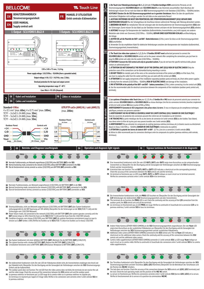
1. The Touch Line video door systems for 1, 2, 3, 4 or 5 Families DO NOT need authorized personnel to connect the
SCU.VDR03.BLG14 or SCU.VDR03.BLG34 central unit to the power network.
After completing the connections, you just have to plug the SCU central unit cable into the socket (230V/50Hz).
ATTENTION!!! Connect the SCU central unit only to grounded sockets.
If you do not have the specific technical skills, please contact an authorized person!
2. ATTENTION! DO NOT DISMANTLE THE FRONT LID OF THE CENTRAL UNIT (SCU)! RISK OF ELECTRIC SHOCK!
Only the protection cases of the connections can be dismantled during mounting or service.
3. DO NOT TOUCH the metallic parts of the wires or the connection terminals of the central unit (SCU) or of the fuses.
First, you have to unplug the cable from the socket and then you can work with the central unit (SCU).
4. ATTENTION! Do not supply components of the installation separately (outdoor panel, terminals, etc.) from other power supplies
or directly from the network (110/230Vc.a. - 50/60Hz). RISK OF ELECTRIC SHOCK and damage of the installation.
5. PAY ATTENTION at the polarity of the BAT+ and BAT- battery connections (12Vd.c.) when connecting it to the central unit (SCU).
6. Use the recommended cable for electrical connections between the components of the installation (outdoor panel, central unit,
terminals).
1
EN
1
SAFETY INSTRUCTIONS for the Touch Line video door systems
with 1-5 Families

2Description of the supply and command central units (SCU)
1. SCU.VDR03.BLG14 – central unit for the standard TL 4 WIRE video door systems with 1, 4 or 5 Families.
2. SCU.VDR03.BLG34 - central unit for the standard TL 4 WIRE video door systems with 2 or 3 Families.
3. The central units (SCU) allow direct connection of other additional devices:
External video cameras (analog, PAL/SECAM, 1 Vp.p.);
Diverse door locks (max. 3A/24Va.c.; max. 3A/24 Vd.c.):
1. Normally open relay - NO (Normal Open)
2. Normally closed relay - NC (Normal Closed)
Auxiliary systems - AUX (1,2): auto gate, garage door, outdoor lighting, etc. - normally open relay contact (NO);
EXIT button for opening the door/ gate from the inside (home, yard);
Video recording devices (DVR);
Rechargeable battery (12Vd.c., 12Ah).
4. The system programming mode is set and reset by pressing the PROG button.
The programming mode is signaled by the red PROG LED.
5. Diagnosis with light signals: network; +14 supply voltage; battery status; shortcircuit at the terminals;
shortcircuit at the additional video camera; shortcircuit at the outdoor panel; lack of the C/D control signal of the
video door system.
Power supply voltage: 110/230Va.c. - 50/60Hz
(from a grounded socket)
Dimensions: 130 x 141 x 73 mm
Weight: 0.4 Kg
o o
Operating temperature range: 0 - 40 C
UL certified printed circuit board
Case: PA6.6 + FS 10% (fireproof)
EN
2
Output voltage (+14): 13,5 - 14,0 Vd.c. max. 2.5Ad.c.
Overload protection for the input and output current
Accidental overvoltage protection

C/D
6mm
25-30mm
GND
Vin
+14V
1. No authorized personnel is required for the installation and commissioning of the Touch Line video door systems for
1-5 Families (DIY)!
2. The supply and command central units will be installed inside the building. They can be mounted on a DIN rail (46277-3,
EN50022, IEC60715) or directly on the wall and they will be connected to the 110/230Va.c. - 50/60Hz network through
a grounded socket.
3. For mounting, operation and service/ maintenance, it is mandatory to comply with the SAFETY INSTRUCTIONS
presented in Ch. 1 of this user manual.
+14V
C/D
6mm
25-30mm
GND
Vout
Recommended cables for the Touch Line video door systems
3
EN
3
Recommended installation cables:
2
4 wires x 0.5 mm (type H03VV-F4G 0.5) for max. 60 ml
2
4 wires x 0.75 mm (type H05VV-F4G 0.75) for max. 100 ml
Significance of the connections:
+14V : the (+) connection for power supplying the system components (= 12 14V)
C/D : the connection for audio communication (analog) and digital data transmission (CAN)
GND : the (-) connection for power supplying the system components (GND = 0V)
Vin/Vout : the connection for video signals transmission - PAL/SECAM analog 1Vpp
Example: +14V = red, C/D = blue, GND = black, Vin/Vout = green. Maintain the same colors for the same connections
throughout the system.
UTP/FTP cat5e (AWG24) or UTP/FTP cat6 (AWG23)
for max. 150 ml
+14
C/D
GND
20-25mm
6mm
Vin
+14
C/D
GND
20-25mm
6mm
Vout

+14
OTHER VIDEO CAMERA DVR AUX1 AUX2 OUT1 OUT2 OUT3
Vout3
GND
CD
+14
Vout2
GND
CD
+14
Vout1
GND
CD
+14
GNV
AUX2
AUX2
AUX1
AUX1
OFF ON
GNV
Vout
+12
GND
Vin2
OFF ON
+14
C/D
GND
Vout
Connections for the Touch Line video door systems with 1 Family
4.1
AUX1
BAT
DOOR LOCK
LOCK
SUPPLY
VIDEO DOOR PANEL
+14
CD
GND
Vin1
GNV
EXIT
EXIT
LCK
LCK
NO NC
10 SEC
BAT
BAT
FUSE - T1.6A
2 SEC
AC. 110/230V
Vcam
Outdoor panel
CAM switch
0 - without additional video camera
1 - with additional video camera
DVR switch
- without DVR
- video recording on the DVR
0
1
Note: The Fam. 1 terminal is programmed from the factory with address 1.
Grounded socket
110/230Va.c. - 50/60Hz
Important!
+14
C/D
GND
Vin
Fam. 1
(address 1)
SCU
Terminal
Central unit type SCU.VDR03.BLG14
max.12Ah/12V
+
-
BAT
AUX2
Fam. 1 (address 1)
GONG
DOORBELL
EN
4
DVR

OTHER VIDEO CAMERA DVR AUX1 AUX2 OUT1 OUT2 OUT3
Vout3
GND
CD
+14
Vout2
GND
CD
+14
Vout1
GND
CD
+14
GNV
AUX2
AUX2
AUX1
AUX1
OFF ON
GNV
Vout
+12
GND
Vin2
OFF ON
BAT
DOOR LOCK
LOCK
SUPPLY
VIDEO DOOR PANEL
+14
CD
GND
Vin1
GNV
EXIT
EXIT
LCK
LCK
NO NC
10 SEC
BAT
BAT
FUSE - T1.6A
2 SEC
AC. 110/230V
Grounded socket
110/230Va.c. - 50/60Hz
Important!
max.12Ah/12V
+
-
BAT
+14
C/D
GND
Vout
+14
C/D
GND
Vin
Fam. 1 (address 1)
+14
C/D
GND
Vin
+14
C/D
GND
Vin
Note: The Fam. 1 terminal is programmed from the factory with address 1.
The Fam. 2 terminal must be programmed with address 2.
The Fam. 3 terminal must be programmed with address 3.
Outdoor panel
SCU
Terminals
GONG
DOORBELL
Central unit type SCU.VDR03.BLG34
Fam. 2 (address 2)
GONG
DOORBELL
Fam. 3 (address 3)
GONG
DOORBELL
Vcam
Connections for the Touch Line video door systems with 2 or 3 Families
4.2 EN
CAM switch
0 - without additional video camera
1 - with additional video camera
DVR switch
- without DVR
- video recording on the DVR
0
1
+14
EN
5
AUX1AUX2
DVR

Connections for the Touch Line video door systems with 4 or 5 Families
4.2
+14
C/D
GND
Vout
Outdoor panel
CAM switch
0 - without additional video camera
1 - with additional video camera
DVR switch
- without DVR
- video recording on the DVR
0
1
SCU
Central unit type SCU.VDR03.BLG14
EN
6
+14
OTHER VIDEO CAMERA DVR AUX1 AUX2 OUT1 OUT2 OUT3
Vout3
GND
CD
+14
Vout2
GND
CD
+14
Vout1
GND
CD
+14
GNV
AUX2
AUX2
AUX1
AUX1
OFF ON
GNV
Vout
+12
GND
Vin2
OFF ON
AUX1
BAT
DOOR LOCK
LOCK
SUPPLY
VIDEO DOOR PANEL
+14
CD
GND
Vin1
GNV
EXIT
EXIT
LCK
LCK
NO NC
10 SEC
BAT
BAT
FUSE - T1.6A
2 SEC
AC. 110/230V
Vcam
Grounded socket
110/230Va.c. - 50/60Hz
Important!
max.12Ah/12V
+
-
BAT
AUX2
DVR

Note: The Fam. 1 terminal is programmed from the factory with address 1.
The Fam. 2 terminal must be programmed with address 2.
The Fam. 3 terminal must be programmed with address 3.
The Fam. 4 terminal must be programmed with address 4.
The Fam. 5 terminal must be programmed with address 5.
EN
7
Fam. 2 (address 2)
GONG
DOORBELL
+14
C/D
GND
Vin
Fam. 4 (address 4)
GONG
DOORBELL
+14
C/D
GND
Vin
+14
C/D
GND
Vin
Fam. 1 (address 1)
GONG
DOORBELL
Fam. 3 (address 3)
GONG
DOORBELL
+14
C/D
GND
Vin
Fam. 5 (address 5)
GONG
DOORBELL
+14
C/D
GND
Vin
+14
C/D
GND
Vin
VCB.4DN03.BLG04

Connections for separate powered AC lock (max. 3A)
BAT
DOOR LOCK
LOCK
SUPPLY
VIDEO DOOR PANEL
+14
CD
GND
Vin1
GNV
EXIT
EXIT
LCK
LCK
NO NC
10 SEC
BAT
BAT
FUSE - T1.6A
2 SEC
AC. 110/230V
+14
C/D
GND
Vout
5.1
EXIT
Lock
12 24V, max. 3A 12 24V, max. 3A
Transformer
2
2 x 0,75 mm
2
2 x 0,75 mm
2
2 x 0,5 mm
Important!
Grounded socket
110/230Va.c. - 50/60Hz
LCK
IMPORTANT: A separate transformer ( 12/24V, max.3A) will be connected at the LOCK SUPPLY terminals.
The AC lock 12/24V, max.3A, will be connected at the LCK1, LCK2 terminals.
Valid for all types of Touch Line installations.
Outdoor panel
SCU
EN
8
+14
NC -
NO -
LCK
LCK
LCK
LCK
2 sec.
10 sec.

Connections for separate powered DC lock (max. 3A)
5.2
+
+14
C/D
GND
Vout
EXIT
LOCK
12 24V, max.3A
2
2 x 0,75 mm
2
2 x 0,5 mm
IMPORTANT: A separate DC power supply ( =12/24V, max.3A) will be connected at the LOCK SUPPLY terminals.
The DC lock =12/24V, max.3A, will be connected at the LCK1, LCK2 terminals.
Valid for all types of Touch Line installations.
12 24V, max.3A
Outdoor panel
LCK
2
2 x 0,75 mm
Important!
Grounded socket
110/230Va.c. - 50/60Hz
BAT
DOOR LOCK
LOCK
SUPPLY
VIDEO DOOR PANEL
+14
CD
GND
Vin1
GNV
EXIT
EXIT
LCK
LCK
NO NC
10 SEC
BAT
BAT
FUSE - T1.6A
2 SEC
AC. 110/230V
+14
SCU
NC -
NO -
LCK
LCK
LCK
LCK
2 sec.
10 sec.
EN
9

BAT
DOOR LOCK
LOCK
SUPPLY
VIDEO DOOR PANEL
+14
CD
GND
Vin1
GNV
EXIT
EXIT
LCK
LCK
NO NC
10 SEC
BAT
BAT
FUSE - T1.6A
2 SEC
AC. 110/230V
+14
Connections for separate powered impulse control DC lock (max. 3A)
5.3
Valid for all types of Touch Line installations.
Lock
+
+14
C/D
GND
Vout
2
2 x 0,5 mm
+
IMPULSE
+14
C/D
GND
Vin1
12 24V, max. 3A
Outdoor panel
Important!
Grounded socket
110/230Va.c. - 50/60Hz
EXIT
2
2 x 0,75 mm
2
1 x 0,5 mm
EN
10 SCU
NC -
NO -
LCK
LCK
LCK
LCK
2 sec.
10 sec.

Connections for internal powered DC lock in the +14/ GND terminals
of the SCU (max. 0.6A)
5.4
12V 0.6A max.
+14
C/D
GND
Vout
EXIT
Lock
IMPORTANT: The LOCK SUPPLY terminals (+/- ) will be connected at the +14 and GND terminals of the VIDEO DOOR PANEL
connector through 2 wires. The DC lock =12V, max. 0.6A, will be connected at the LCK1, LCK2 terminals.
Valid for all types of Touch Line installations.
Outdoor panel
LCK
2
2 x 0,5 mm
2
2 x 0,5 mm
SCU
BAT
DOOR LOCK
LOCK
SUPPLY
VIDEO DOOR PANEL
+14
CD
GND
Vin1
GNV
EXIT
EXIT
LCK
LCK
NO NC
10 SEC
BAT
BAT
FUSE - T1.6A
2 SEC
AC. 110/230V
+14
NC -
NO -
LCK
LCK
LCK
LCK
2 sec.
10 sec.
EN
11

Connection of Digital Video Recorder (DVR)
7
Connection of auxiliary installations
6
The additional installations (auto gate, garage door, outdoor lighting, etc.) will be connected at the AUX1, AUX2
terminals of the central unit and will be commanded from the keyboard of any Touch Line terminal.
The AUX1, AUX2 contacts will close for 2 seconds and sustain a maximum current of 0.5A.
2 sec.
( )12/24V/0,5A
to the 1st additional installation
EN
12
Vin2
OTHER VIDEO
AUX 1
AUX 1
AUX 2
AUX 2
+BAT
AUX1
AUX2BAT
to the 2nd additional installation
OTHER VIDEO CAMERA DVR AUX1 AUX2 OUT1 OUT2 OUT3
Vout3
GND
CD
+14
Vout2
GND
CD
+14
Vout1
GND
CD
+14
GNV
AUX2
AUX2
AUX1
AUX1
OFF ON
GNV
Vout
+12
GND
Vin2
OFF ON
Vcam DVR
Display
110/230Va.c. - 50/60Hz
NO
NO
Power Supply
12V

+14
Programming the Touch Line video door systems
8
Programming mode: long press (3 sec.)
of the PROG. button
You can program:
1) The address of the terminal (housing number).
The programming is done following the procedure in the audio-video terminals manual. All terminals are programmed from
the factory with Address 0001.
2) The address of outdoor panels (2, 3 or 4), when the system has additional outdoor panels.
The programming is done following the procedure in the video panels manual. All panels are programmed in the factory
with Address 1.
3) The storage/deletion/addition of the RFID access CARDS (according to the procedure in the video panels manual).
Exiting programming mode is done by short pressing the PROG. button. The PROG red LED turns off.
The PROG red LED turns on and
remains on during the entire
programming phase.
EN
13

+14
+14
+14
+14
+14
+14
+14
+14
1. Normal functioning mode, connected to the network (110/230V),
without BATTERY (BAT) connected in the SCU.
Diagnosis and service for the Touch Line video door systems with 1-5 Families
9
2. Normal functioning mode, connected to the network (110/230V),
with BATTERY (BAT) connected in the SCU.
3. Power failure mode, not connected to the network
(110/230V), with BATTERY (BAT) (the system operates correctly
until the BAT tension drops to 10V). Check the fuses on the SCU (FUSE T-1.6A) and the fuses from the 110/230V network.
4. The system function with a broken BATTERY (BAT). Replace the
BATTERY (BAT) (12Ah/12V).
5. The outdoor panel does not function. The red LED from
the video camera does not blink, the terminals do not receive
the call and the video image. Check the accuracy of the connections between the SCU central unit and the outdoor panel.
6. A terminal does not function. The red OUT1, OUT2 or OUT3 LED
indicates a shortcircuit on the corresponding terminal.
Check the accuracy of the connections between the SCU central unit and the terminals.
7. The terminals do no function, the PROG LED is red. Check the
continuity and the accuracy of the C/D connection from the
outdoor panel, the SCU central unit and all the terminals.
9. The lock does not function. Check the accuracy of the connections between the SCU central unit (LCK1, LCK2 terminals) and the
lock. Check the lock operating mode and the position of the NO/ NC switch.
8. Additional video camera (OTHER VIDEO CAMERA) connected to
the SCU central unit. The red Vcam LED indicates a shortcircuit on
the additional video camera. Check the continuity and the accuracy of the connections between the SCU central unit and the additional
video camera.
EN
14

2 2
3 4
10. If the SCU central unit fails, it will be replaced with a new one. In order not to reprogram already stored RFID cards, you will need to
remove the EEPROM memory from the defective SCU central unit and insert it into the new SCU central unit, replacing the existing one.
When fixing the EEPROM memory, it is mandatory to keep the same position of the first pin!ATTENTION!
EN
15

10 Declaration of conformity. Warranty.
1. A 24-month warranty is granted, according to the existing legislation, based on the purchase document.
2. Warranty is granted for non-conformity and/or hidden defects.
3. Warranty is NOT granted for:
- Missing purchase documents;
- Incorrect installation, non-compliant with this manual (e.g.: wrong supply voltage);
- Incorrect operation, non-compliant with this manual (e.g.: wrong settings);
- Broken glass and/or other damage, blows, mechanical shocks;
- Theft, fire, floods, natural disasters;
- Unprotected product during renovation activities;
- Use of the product in systems that require different performance parameters from the ones provided by the
technical specifications in this manual;
- The RFID access cards (tags), which are considered consumables.
For complaints during the warranty period, please contact the company from which you have purchased the product.
The manufacturer ELECTRA s.r.l. declares that:
The products are in compliance with the harmonised legislation of the European Union regarding the directives:
Low Voltage (LVD) 2014/35; Electromagnetic compatibility (EMC) 2014/30/EC; RoHS 2011/65/EC.
The following harmonised standards and technical specifications have been applied: SR EN 60950-1:2006
+ A1:2011 + A2:2014 + A11:2009 + A12:2014 + AC:2011 + C91:2010; SR EN 55022:2011 + AC:2011;
SR EN 55024:2011 + A1:2015; SR EN 61000-3-2 2015; SR EN 61000-3-3:2014.
The products do not threaten life, health, work safety, do not have any negative effect on the environment and
have been produced under the ISO 9001:2015/ ISO 14001:2015 Quality and Environment Management System
certified by TÜV HESSEN.
Warranty
EN
16


03.2021 USM.SCU.VDR03.BLY34
Designed and produced by ELECTRA Made in EU
Certificate no. E307311
ISO 9001:2015
ISO 14001:2015
Certificates no. 73 100 4856, 73 104 4856
by TÜV HESSEN
The products are manufactured under
Quality and Environment Management System
The products are
CE certified.
R
The products contain UL-compliant
printed circuit boards.
Certificate by
R709 ICPE
BELLCOME is a trademark of ELECTRA Group - No. 013502646 - EUIPO - Alicante, Spain
BELLCOME/ELECTRA products are registered as Industrial Models - EUIPO - Alicante, Spain
SUPPORT
ELECTRA Building Communications GmbH
Bischoffgasse 5/3-4,
1120 Wien - AT
+43 1 810 20 99
www.bellcome.com
MADE in EU by:
ELECTRA s.r.l
Parc Industrial Miroslava
Str. Principala 33, 707307, Jud. Iași - RO
+40 232 214.370
www.electra.ro
Other manuals for Touch Line SCU.VDR03.BLG14
1
This manual suits for next models
1
Table of contents
Other Bellcome Power Supply manuals
Popular Power Supply manuals by other brands
INIM Electronics
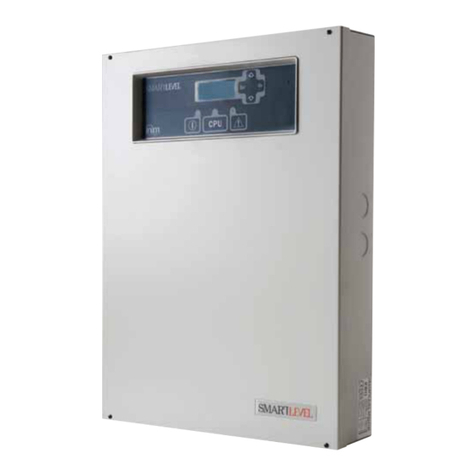
INIM Electronics SmartLevel SPS24040 Installation and programming manual
Pulsar
Pulsar PSAC 04244SEP manual
LionTec
LionTec MPS-2302000 Operating instruction
Siemens
Siemens SITOP PSU8200 24 V/20 A user manual
ADTRAN
ADTRAN NetVanta 1000 Series Installation and Maintenance

VOLTCRAFT
VOLTCRAFT SNPS-90 operating instructions
