Bellcome Touch Line SCU.VDR03.BLG14 User manual
BENUTZERHANDBUCH
Stromversorgungseinheit
DE
USER MANUAL
Supply central unit
EN
MANUEL D`UTILISATEUR
Unité centrale d'alimentation
FR
130 x 140 x 73 mm / 0,4 kg
Power supply voltage: 110/230Va.c. - 50/60Hz (from a grounded socket)
Output voltage (+14): 13,5 - 14,0 Vd.c. max. 2.5Ad.c.
Overload protection for the input and output current
o o
Operating temperature range: 0 - 40 C
Case: PA6.6 + FS 10% (fireproof)
2DE
EN
FR
Kabel und Installation
Cables and installation
Câbles et installation
+14
C/D
6mm
20-25mm
GND
Vin
+14
C/D
6mm 20-25mm
GND
Vout
Outdoor Panel Central unit
Standard 4 Wire
2 2
4 x 0.5 mm (max. 60m); 4 x 0.75 mm (max. 100m);
TCYY – 2x2x0.5-24 AWG (max. 30m);
TCYY – 3x2x0.5-24 AWG (max. 50m);
TCYY – 4x2x0.5-24 AWG (max. 50m)
UTP/FTP cat5e (AWG24) / cat6 (AWG23)
(max. 200m)
+14
C/D
GND
20-25mm
6mm
Vin
+14
C/D
GND
20-25mm
6mm
Vout
DE
Sicherheitshinweise
1
Instructions de sécurité
FR
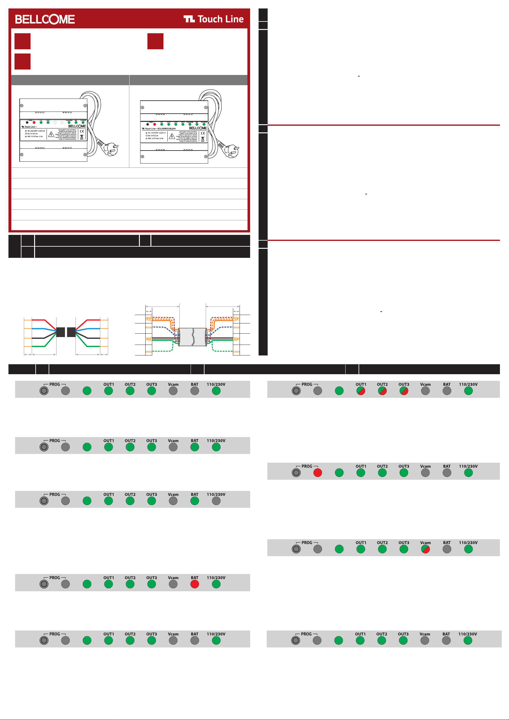
3DE Betriebs- und Diagnose-Leuchtsignale EN Operation and diagnosis light signals FR Signaux lumineux de fonctionnement et de diagnostic
Normaler Funktionsmodus, ans Netzwerk angeschlossen (110/230V), ohne BATTERIE (BAT) in der SCU.
Normal functioning mode, connected to the network (110/230V), without BATTERY (BAT) connected in the SCU.
État de fonctionnement normal, connecté au secteur (110/230V), sans BATTERIE (BAT) connectée au SCU.
Normaler Funktionsmodus, ans Netzwerk angeschlossen (110/230V), mit BATTERIE (BAT) in der SCU.
Normal functioning mode, connected to the network (110/230V), with BATTERY (BAT) connected in the SCU.
État de fonctionnement normal, connecté au secteur (110/230V), avec BATTERIE (BAT) connectée au SCU.
Stromausfallmodus, nicht ans Netzwerk angeschlossen (110/230V), mit BATTERIE (BAT) (das System funktioniert
ordnungsgemäß, bis die BAT-Spannung auf 10V abfällt). Überprüfen Sie die Sicherungen an der SCU (FUSE T-1.6A) und die
Sicherungen vom 110/230V Netzwerk.
Power failure mode, not connected to the network (110/230V), with BATTERY (BAT) (the system operates correctly until the
BAT tension drops to 10V). Check the fuses on the SCU (FUSE T-1.6A) and the fuses from the 110/230V network.
Condition d'urgence, sans réseau (110/230V), avec BATTERIE (BAT) (le système fonctionne correctement jusqu'à ce que la
tension sur la BAT tombe à 10V). Vérifiez les fusibles sur le SCU (FUSE T-1.6A) et les fusibles sur le réseau 110/230V.
Das System funktioniert mit einer defekten BATTERIE (BAT). Wechseln Sie die BATTERIE (BAT) (12Ah/12V).
The system function with a broken BATTERY (BAT). Replace the BATTERY (BAT) (12Ah/12V).
L'installation fonctionne avec la BATTERIE (BAT) défectueuse. Remplacez la BATTERIE (BAT) (12Ah/12V).
Die Außeneinheit funktioniert nicht. Die rote LED der Videokamera blinkt nicht, die Inneneinheiten empfangen den Anruf und
das Videobild nicht. Überprüfen Sie den Durchgang und die Genauigkeit der Verbindungen zwischen der SCU-Stromversorgungs-
Einheit und der Außeneinheit.
The outdoor panel does not function. The red LED from the video camera does not blink, the terminals do not receive the call
and the video image. Check the accuracy of the connections between the SCU central unit and the outdoor panel.
Le panneau extérieur ne fonctionne pas. La LED rouge de la caméra vidéo sur le panneau extérieur ne clignote pas,
les terminaux ne reçoivent pas l'appel et l'image vidéo. Vérifiez si les connexions sont correctes entre l`unité centrale SCU et
le panneau extérieur.
Eine Inneneinheit funktioniert nicht. Die rote LED OUT1, OUT2 oder OUT3 zeigt einen Kurzschluss an der entsprechenden
Inneneinheit an. Überprüfen Sie den Durchgang und die Genauigkeit der Verbindungen zwischen der SCU-Stromversorgungs-
Einheit und der Inneneinheiten.
A terminal does not function. The red OUT1, OUT2 or OUT3 LED indicates a shortcircuit on the corresponding terminal.
Check the accuracy of the connections between the SCU central unit and the terminals.
Un terminal ne fonctionne pas. La LED rouge OUT1, OUT2 ou OUT3 indique un court-circuit sur le terminal concerné.
Vérifiez les connexions correctes entre l`unité centrale SCU et les terminaux.
Die Inneneinheiten funktionieren nicht, die PROG-LED leuchtet rot. Überprüfen Sie den Durchgang und die Genauigkeit der
C/D Verbindungen der Außeneinheit, SCU-Stromversorgungseinheit und aller Inneneiheiten.
The terminals do no function, the PROG LED is red. Check the continuity and the accuracy of the C/D connection from the
outdoor panel, the SCU central unit and all the terminals.
Les terminaux ne fonctionnent pas, la LED PROG est rouge. Vérifiez la continuité et l'exactitude de la connexion C/D sur le
panneau extérieur, l`unité centrale SCU et tous les terminaux.
Andere Video-Kamera (OTHER VIDEO CAMERA) an die SCU-Stromversorgungseinheit angeschlossen. Die rote Vcam-LED
zeigt einen Kurzschluss an der zusätzlichen Videokamera an. Überprüfen Sie den Durchgang und die Genauigkeit der
Verbindungen zwischen der SCU-Stromversorgungseinheit und der zusätzlichen Videokamera.
Additional video camera (OTHER VIDEO CAMERA) connected to the SCU central unit. The red Vcam LED indicates a
shortcircuit on the additional video camera. Check the continuity and the accuracy of the connections between the SCU
central unit and the additional video camera.
Caméra vidéo supplémentaire (OTHER VIDEO CAMERA) connectée à l`unité centrale SCU. La LED rouge Vcam indique un
court-circuit sur la caméra vidéo. Vérifiez la continuité et l'exactitude des connexions entre l`unité centrale SCU et la caméra
vidéo supplémentaire.
Das Türschloss funktioniert nicht. Überprüfen Sie den Durchgang und die Genauigkeit der Verbindungen zwischen der SCU
Stromversorgungseinheit und dem Türschloss (LCK1, LCK2 Klemmen). Überprüfen Sie die Betriebsart des Türschlosses und
die Position des NO/NC-Schalters.
The lock does not function. Check the accuracy of the connections between the SCU central unit (LCK1, LCK2 terminals) and
the lock. Check the lock operating mode and the position of the NO/ NC switch.
La serrure ne fonctionne pas. Vérifiez les connexions correctes entre l`unité centrale SCU (bornes LCK1, LCK2) et la serrure.
Vérifiez le fonctionnement de la serrure et la position du commutateur NO/NC.
DE
EN
FR
DE
EN
FR
DE
EN
FR
DE
EN
FR
DE
EN
FR
+14
+14
+14
+14
+14
+14
DE
EN
FR
+14
DE
EN
FR
+14
DE
EN
FR
DE
EN
FR
1. Die Touch Line-Videotürsprechanlagen für 1, 2, 3, 4 oder 5 Familien benötigen KEIN autorisiertes Personal, um die
Stromversorgungseiheit SCU.VDR03.BLG14 oder SCU.VDR03.BLG34 an das Stromnetz anzuschließen. Nach Abschluss der
Verbindungen müssen Sie nur noch das Kabel der SCU-Stromversorgungseiheit in die Steckdose (110/230Va.c. - 50/60Hz) stecken.
ACHTUNG!!! Stecken Sie die SCU-Stromversorgungseinheit nur in geerdete Steckdosen. Wenn Sie über die spezifischen
technischen Fähigkeiten nicht verfügen, wenden Sie sich bitte an eine autorisierte Person!
2. ACHTUNG! ENTFERNEN SIE NICHT DEN FRONTDECKEL DER STROMVERSORGUNGSEINHEIT (SCU)! GEFAHR EINES
ELEKTRISCHEN SCHLAGS! Nur die Schutzgehäuse der Anschlüsse können während der Montage oder Wartung demontiert werden.
3. BERÜHREN SIE NICHT die metallischen Teile der Leitungen oder die Anschlussklemmen der Stromversorgungseinheit (SCU) oder
der Sicherungen. Zuerst müssen Sie das Kabel aus der Steckdose trennen und dann mit der Stromversorgungseinheit (SCU) arbeiten.
4. ACHTUNG! Versorgen Sie Komponenten der Installation (Außeneinheiten, Inneneinheiten, usw.) nicht separat, von anderen
Netzteilen oder direkt vom Stromnetz (110/230Va.c. - 50/60Hz). GEFAHR EINES ELEKTRISCHEN SCHLAGS und Beschädigung
der Anlage.
5. ACHTEN SIE auf die Polarität der BAT+ und BAT - Batterieklemmen (12Vd.c.) wenn Sie diese an die Stromversorgungseinheit
(SCU) anschließen.
6. Verwenden Sie das empfohlene Kabel für elektrische Verbindungen zwischen den Komponenten der Installation (Außeneinheit,
Stromversorgungseinheit, Inneneinheiten).
1. Les systèmes d'interphone vidéo Touch Line pour 1, 2, 3, 4 ou 5 familles N'ont PAS besoin de personnel autorisé pour connecter les
unités centrales SCU.VDR03.BLG14 ou SCU.VDR03.BLG34 au réseau électrique. Une fois les connexions terminées, branchez simplement
la fiche de l'unité centrale SCU dans la prise (230Vc.a./50Hz).
AVERTISSEMENT!!! Connectez le SCU uniquement à des prises mises à la terre. Si vous ne disposez pas de compétences techniques
spécifiques, contactez une personne autorisée !
2. AVERTISSEMENT! NE PAS RETIRER LE COUVERCLE AVANT DE L'UNITÉ CENTRALE (SCU) ! DANGER DE CHOC ÉLECTRIQUE !
Seuls les couvercles de protection des connexions peuvent être retirés lors de l'installation ou de l'entretien.
3. NE TOUCHEZ PAS la partie métallique des fils ou des bornes de connexion de l'unité centrale (SCU) ou des fusibles. Tout d'abord,
vous devez retirer la fiche de la prise, puis vous pouvez travailler avec l'unité centrale (SCU).
4. AVERTISSEMENT! Ne pas alimenter les composants du système (panneau extérieur, terminaux, etc.) à d'autres sources ou directement
depuis le réseau 110/230Vc.a. - 50/60Hz). DANGER DE CHOC ÉLECTRIQUE et destruction du système.
5. ATTENTION à la polarité des bornes de batterie BAT+ et BAT- (12 Vc.c.) lors de sa connexion à l'unité centrale (SCU).
6. Utilisez le câble recommandé pour les connexions électriques entre les composants du système (panneau extérieur, unité centrale,
terminaux).
EN
Safety instructions
1. The Touch Line video door systems for 1, 2, 3, 4 or 5 Families DO NOT need authorized personnel to connect the
SCU.VDR03.BLG14 or SCU.VDR03.BLG34 central unit to the power network. After completing the connections, you just have to
plug the SCU central unit cable into the socket (110/230Va.c. - 50/60Hz).
ATTENTION!!! Connect the SCU central unit only to grounded sockets. If you do not have the specific technical skills, please
contact an authorized person!
2. ATTENTION! DO NOT DISMANTLE THE FRONT LID OF THE CENTRAL UNIT (SCU)! RISK OF ELECTRIC SHOCK! Only the
protection cases of the connections can be dismantled during mounting or service.
3. DO NOT TOUCH the metallic parts of the wires or the connection terminals of the central unit (SCU) or of the fuses. First,
you have to unplug the cable from the socket and then you can work with the central unit (SCU).
4. ATTENTION! Do not supply components of the installation separately (outdoor panel, terminals, etc.) from other power supplies
or directly from the network (110/230Va.c. - 50/60Hz). RISK OF ELECTRIC SHOCK and damage of the installation.
5. PAY ATTENTION at the polarity of the BAT+ and BAT - battery connections (12Vd.c.) when connecting it to the central unit (SCU).
6. Use the recommended cable for electrical connections between the components of the installation (outdoor panel, central unit,
terminals).
S2: BAT. 12V/3.4÷7Ah
S1: 13.5V, 2.0A
SCU.VDR03.BLG14
S2: BAT. 12V/3.4÷7Ah
S1: 13.5V, 2.0A
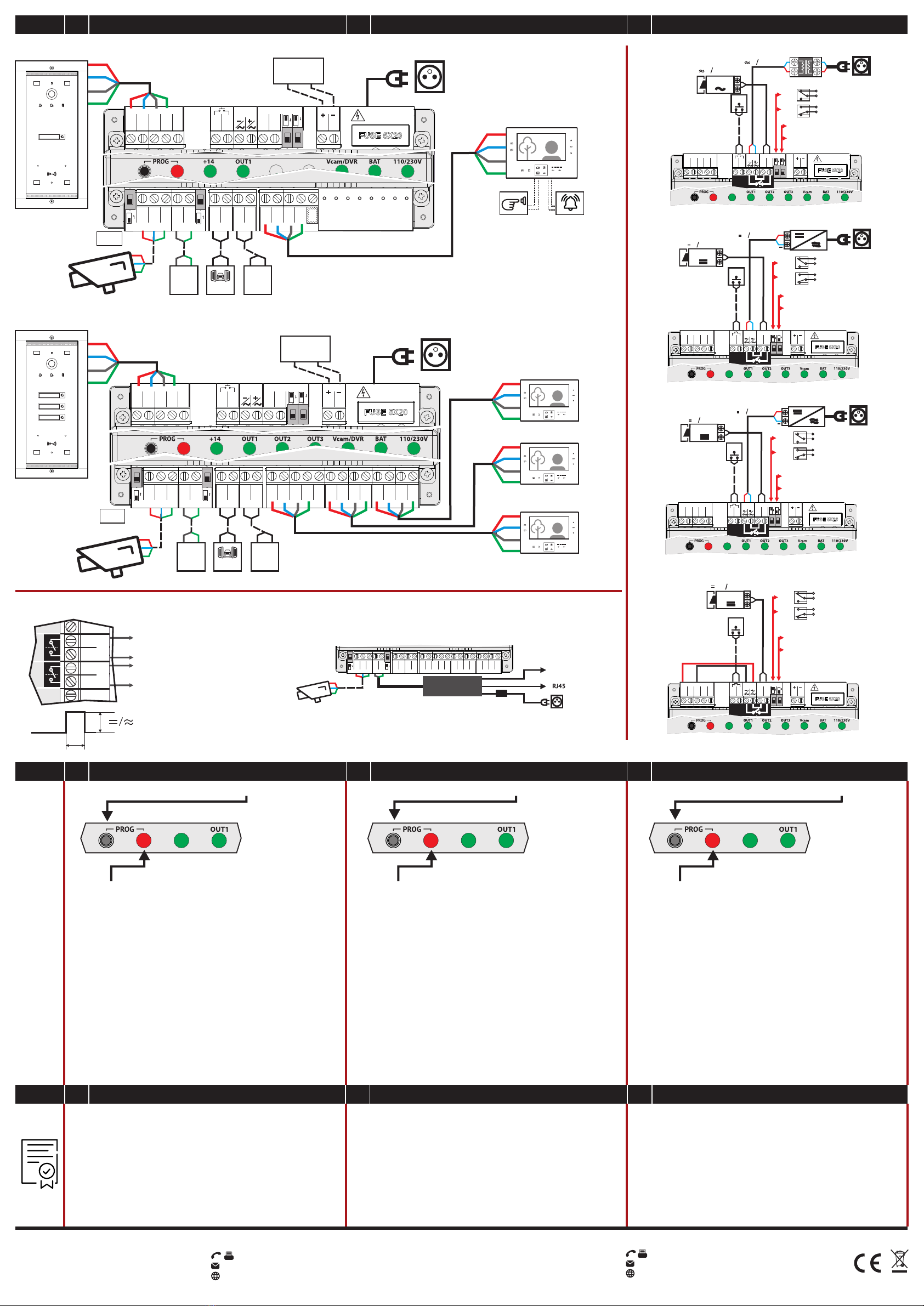
3 Outputs - SCU.VDR03.BLG341 Output - SCU.VDR03.BLG14
+14
Outdoor Panel Central unit
+14
OTHER VIDEO CAMERA DVR AUX1 AUX2 OUT1 OUT2 OUT3
Vout3
GND
CD
+14
Vout2
GND
CD
+14
Vout1
GND
CD
+14
AUX2
AUX2
AUX1
AUX1
OFF ON
GNV
Vout
+12
GND
Vin2
OFF ON
GNV
BAT
DOOR LOCK
LOCK
SUPPLY
VIDEO DOOR PANEL
+14
CD
GND
Vin1
GNV
EXIT
EXIT
LCK
LCK
NO NC
10 SEC
BAT
BAT
FUSE - T1.6A
2 SEC
AC. 110/230V
+14
C/D
GND
Vout
SCU
SCU.VDR03.BLG14 12V/max.12Ah
+
-
BAT
AUX1AUX2
Vcam DVR
GROUNDED OUTLET
110/230Va.c.
50/60Hz
Fam. 1 (address 1)
GONG
DOORBELL
+14
C/D
GND
Vout
OTHER VIDEO CAMERA DVR AUX1 AUX2 OUT1 OUT2 OUT3
Vout3
GND
CD
+14
Vout2
GND
CD
+14
Vout1
GND
CD
+14
GNV
AUX2
AUX2
AUX1
AUX1
OFF ON
GNV
Vout
+12
GND
Vin2
OFF ON
BAT
DOOR LOCK
LOCK
SUPPLY
VIDEO DOOR PANEL
+14
CD
GND
Vin1
GNV
EXIT
EXIT
LCK
LCK
NO NC
10 SEC
BAT
BAT
FUSE - T1.6A
2 SEC
AC. 110/230V
+14
+14
C/D
GND
Vout
Outdoor panel
SCU
SCU.VDR03.BLG34 12V/max.12Ah
+
-
BAT
AUX1
Vcam AUX2
DVR
GROUNDED OUTLET
110/230Va.c.
50/60Hz
+14
C/D
GND
Vout
+14
C/D
GND
Vout
+14
C/D
GND
Vout
+
EXIT
NC -
NO -
LOCK
12 24V, max.3A
LCK
LCK
LCK
LCK
2
2 x 0,75 mm
2
2 x 0,5 mm
12 24V, max.3A
LCK
2 sek.
10 sek.
BAT
DOOR LOCK
LOCK
SUPPLY
VIDEO DOOR PANEL
+14
CD
GND
Vin1
GNV
EXIT
EXIT
LCK
LCK
NO NC
10 SEC
BAT
BAT
FUSE - T1.6A
2 SEC
AC. 110/230V
+14
EXIT NC -
NO -
Lock
12 24V, max. 3A
12 24V, max. 3A
Transformer
LCK
LCK
LCK
LCK
2
2 x 0,75 mm
2
2 x 0,75 mm
2
2 x 0,5 mm
LCK
2 sek.
10 sek.
BAT
DOOR LOCK
LOCK
SUPPLY
VIDEO DOOR PANEL
+14
CD
GND
Vin1
GNV
EXIT
EXIT
LCK
LCK
NO NC
10 SEC
BAT
BAT
FUSE - T1.6A
2 SEC
AC. 110/230V
+14
+
EXIT
NC -
NO -
LOCK
12 24V, max.3A
LCK
LCK
LCK
LCK
2
2 x 0,75 mm
2
2 x 0,5 mm
12 24V, max.3A
LCK
2 sek.
10 sek.
BAT
DOOR LOCK
LOCK
SUPPLY
VIDEO DOOR PANEL
+14
CD
GND
Vin1
GNV
EXIT
EXIT
LCK
LCK
NO NC
10 SEC
BAT
BAT
FUSE - T1.6A
2 SEC
AC. 110/230V
+14
12V 0.6A max.
EXIT
Lock
LCK
2
2 x 0,5 mm
NC -
NO -
LCK
LCK
LCK
LCK
2 sek.
10 sek.
BAT
DOOR LOCK
LOCK
SUPPLY
VIDEO DOOR PANEL
+14
CD
GND
Vin1
GNV
EXIT
EXIT
LCK
LCK
NO NC
10 SEC
BAT
BAT
FUSE - T1.6A
2 SEC
AC. 110/230V
+14
GROUNDED OUTLET
110/230Va.c.
50/60Hz
GROUNDED OUTLET
110/230Va.c.
50/60Hz
GROUNDED OUTLET
110/230Va.c.
50/60Hz
Separate powered AC lock (max. 3A)
Separate powered DC lock (max. 3A)
Separate powered impulse control DC lock (max. 3A)
Internal powered DC lock in the +14/ GND terminals
2
2 x 0,75 mm 2
2 x 0,75 mm
2
2 x 0,5 mm
5DE Systemprogrammiermodus EN System programming mode FR Mode de programmation du système
Sie können programmieren:
1) Die Adresse der Inneneinheit (Wohnungsnummer). Die Programmierung kann
gemäß dem Verfahren aus der Handbuch der Audio-Video-Inneneinheiten
erfolgen. Alle Inneneinheiten sind ab Werk mit Adresse 0001 programmiert.
2) Die Adresse der Außeneinheiten (2, 3 or 4), wenn ein Gebäude mehrere
Eingänge hat. Die Programmierung kann gemäß dem Verfahren aus der Handbuch
der Außeneinheiten erfolgen. Alle Außeneinheiten sind ab Werk mit Adresse 1
programmiert.
3) Das Speichern / Löschen / Hinzufügen der RFID-Zugangs-
KARTEN (gemäß dem Verfahren aus der Handbuch der Außeneinheiten).
Der Programmiermodus wird durch kurzes Drücken der PROG Taste verlassen.
Die rote PROG-LED erlischt.
You can program:
1) The address of the terminal (housing number).
The programming is done following the procedure in the audio-video terminals
manual. All terminals are programmed from the factory with Address 0001.
2) The address of outdoor panels (2, 3 or 4), when the system has additional
outdoor panels. The programming is done following the procedure in the
video panels manual. All panels are programmed in the factory with Address 1.
3) The storage/deletion/addition of the RFID access CARDS
(according to the procedure in the video panels manual).
Exiting programming mode is done by short pressing the PROG. button.
The PROG red LED turns off.
Vous pouvez programmer:
1) L'adresse du terminal (numéro du logement).
La programmation se fait selon la procédure du manuel des terminaux
audio-vidéo Touch Line. Tous les terminaux sont programmés dans la
fabrique avec l'Adresse 0001.
2) L'adresse du panneau extérieur (2, 3 ou 4), lorsque l'installation comporte
plusieurs panneaux. La programmation se fera selon la procédure du manuel
des panneaux extérieurs. Tous les panneaux sont programmés dans la fabrique
avec l'Adresse 1.
3) Stockage/suppression/ajout de CARTES d'accès RFID
(selon la procédure du manuel du panneau extérieur).
La sortie du mode de programmation se fait en appuyant brièvement sur la
touche PROG. La LED rouge PROG s'éteint.
1. Anhand des Kaufdokuments wird gemäß den geltenden Rechtsvorschriften eine
Garantie von 24 Monaten gewährt.
2. Für Fehler und / oder versteckte Mängel wird eine Garantie gewährt.
3. Die Garantie wird NICHT gewährt für: falsche, dem vorliegenden
Bedienerhandbuch nicht entsprechende Installation und/ oder Verwendung;
zerbrochenes Glas, Schläge, mechanische Stöße; Diebstahl, Feuer,
Überschwemmungen, Naturkatastrophen; ungeschütztes Produkt bei
Renovierungsarbeiten; die RFID-Zugangskarten (Tags), die als
Verbrauchsmaterialien gelten.
1. A 24-month warranty is granted, according to the existing legislation, based
on the purchase document.
2. Warranty is granted for non-conformity and/or hidden defects.
3. Warranty is NOT granted for: incorrect installation and/ or operation,
non-compliant with this manual; broken glass, blows, mechanical shocks;
theft, fire, floods, natural disasters; unprotected products during renovation
activities; the RFID access cards (tags), which are considered consumables.
1. Une garantie de 24 mois est accordée conformément à la législation en
vigueur, sur la base du document d'achat.
2. La garantie s'applique en cas de non-conformités et / ou de défauts cachés.
3. La garantie N'EST PAS accordée pour: installation et/ ou fonctionnement
incorrects, non conformes à ce manuel ; verre brisé, coups, chocs mécaniques ;
vol, incendie, inondations, catastrophes naturelles ; produits non protégés
lors des activités de rénovation ; les cartes d'accès RFID (tags), qui sont des
consommables.
06.2023 INS.SCU.VDR03.BLG34
SUPPORT
ELECTRA Building Communications GmbH
Gadnergasse 71, Stockwerk 1, Büro Top 132
1110 Wien - AT
www.bellcome.com
+43 1 810 20 99
MADE in EU by:
ELECTRA s.r.l
Parc Industrial Miroslava
Str. Principala 33, 707307, Jud. Iași - RO
+40 232 214.370
www.electra.ro
6DE Garantie EN Warranty FR Garantie
+14
Programmiermodus: Langes Drücken (3 Sek.) des PROG. Taste.
Die rote LED PROG leuchtet während der gesamten Programmierphase auf und
bleibt eingeschaltet.
+14
Programming mode: long press (3 sec.) of the PROG. button.
The PROG red LED turns on and remains on during the entire programming
phase.
+14
Mode de programmation: appui long (3 sec.) sur le bouton PROG.
La LED PROG s'allume en rouge et reste allumée tout au long de la
programmation.
Fam. 3 (address 3)
Fam. 2 (address 2)
Fam. 1 (address 1)
4DE Schaltpläne EN Connection diagrams FR Schémas de connexion
1 Family
2, 3 Families
Outdoor panel
2 sec.
( )12/24V/0,5A
to the 1st additional installation
to the 2nd additional installation
NO
NO
Vin2
OTHER VIDEO
AUX 1
AUX 1
AUX 2
AUX 2
+BAT
AUX1
AUX2BAT
Connection of auxiliary installations
Vcam DVR
Display
Power Supply
12V
OTHER VIDEO CAMERA DVR AUX1 AUX2 OUT1 OUT2 OUT3
Vout3
GND
CD
+14
Vout2
GND
CD
+14
Vout1
GND
CD
+14
GNV
AUX2
AUX2
AUX1
AUX1
OFF ON
GNV
Vout
+12
GND
Vin2
OFF ON
Connection of Digital Video Recorder (DVR)
110/230Va.c.
50/60Hz
Central unit
Central unit
Name 1
Name 2
Name 3
Name 1
Other manuals for Touch Line SCU.VDR03.BLG14
1
This manual suits for next models
1
Other Bellcome Power Supply manuals

Popular Power Supply manuals by other brands


Allen-Bradley
Allen-Bradley ControlLogix 1756-PA75/B installation instructions

milleteknik
milleteknik 1U01D10024P1501 manual

Wheelock
Wheelock RPS-2440-A installation instructions

WFCO
WFCO WF-8700 Series Operator's manual

Guntermann & Drunck
Guntermann & Drunck MultiPower-6-NT installation guide

Puls
Puls PIANO Series manual


