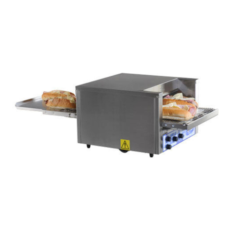
Belleco JSO-14 Installation guide

Foodservice Equipment Specialists
P.O. Box 880 Saco, ME. / U.S.A. 04072
877-854-8006 * FAX (207) 854-8009
OPERATIONS AND MAINTENANCE PROCEDURES
CONVEYOR OVEN MODELS
JSO-14 JPO-18
FOR SERVICE ASSISTANCE
U.S. AND CANADA CALL: 1-877-854-8006
24 HOURS/DAY 7 DAYS/WEEK
TABLE OF CONTENTS
UNCRATNG AND INSPECTION PAGE 1
ASSEMBLY AND INSTALLATION PAGE 1
ELECTRICAL INSTALLATION PAGE 1
COOKING PROCEDURE PAGE 2
CLEANING (DAILY & WEEKLY) PAGE 3
HIGH TEMPERATURE LIMIT PAGE 3
GENERAL MAINTENANCE PAGE 4
TROUBLESHOOTING GUIDE PAGE 5
HEATER TUBE GUIDE PAGE 5
SPARE PARTS LISTINGS PAGE 6
WARRANTY PAGE 7
09-07 RJB

Page 1
OPERATIONS AND MAINTENANCE PROCEDURES
CONVEYOR OVEN MODELS
JSO-14 JPO-18
UNCRATING AND INSPECTION
Unpack the unit and components from the shipping container. Remove all visible packing
materials including those that may be inside the baking chamber. If damage is discovered, file a
claim immediately with the carrier that handled the shipment.
ASSEMBLY AND INSTALLATION
The equipment is shipped fully assembled and ready to plug into a matching outlet specified for
its specific voltage and amperage rating. Removal or replacement of the power cord and plug
will VOID the warranty. For assistance, contact the Belleco, Inc. Service Group at 1-877-854-
8006. Please refer to the appropriate schematic at the rear of this manual for plug configurations.
Consult with a licensed electrician prior to installation. "Do not operate this equipment without
the crumb trays properly installed as this may cause overheating and loss of productivity.
CAUTION – During installation: Do not place on surfaces or near walls, partitions or
kitchen furniture and the like – unless they are made of non-combustible material or clad with
non-combustible heat-insulating material, and pay attention to fire prevention regulations.
CAUTION – To reduce the risk of fire, the appliance is to be installed in non-
combustible surroundings only, with no combustible material within 18 inches of the sides, front,
or rear of the appliance or within 40 inches above the appliance. "Food may burn. Therefore
equipment must not be used near or below curtains and other combustible materials. They must
be watched."
ELECTRICAL INSTALLATION
WARNING – Disconnect the unit from its power source before installing or removing
any parts.
WARNING – Check with your local power company or licensed electrician before
installation to determine the actual voltage at the outlet. For a unit rated 208 volts, never plug it
into 240 volts as serious overheating and damage could occur. For a unit rated 240 volts, never
plug it into 208 volts as the lower voltage will greatly reduce the productivity of the unit.
WARNING – NEVER operate any piece of equipment without proper GROUND
connection. Improper grounding may result in serious personal injury or could be fatal!

PAGE 2
OPERATIONS AND MAINTENANCE PROCEDURES
CONVEYOR OVEN MODELS
JSO-14 JPO-18
POWER SWITCH
FULL POWER – In this position, the equipment is at full heat and ready for use.
OFF – In this position, the equipment is off however, the cooling fans will continue to operate
until the heated chambers are completely cool. This normally takes 15 – 20 minutes.
COOKING PROCEDURE
Bakers with 4” high clearance are equipped with an adjustable heat shield designed to reduce
heat loss through the load and exit end of the unit. The shield should be adjusted so that the
highest product being toasted/baked fits under it. Excess height will allow heat loss through the
front and may reduce capacity.
Toasting JSO Models:
•Turn the Power Switch to the “ON” position.
•Set the Conveyor Speed Control knob to 50.
•Set each Heat Controller (Top and Bottom) to desired range.
•Allow 15-20 minutes to heat from cold.
•Place a sample of the desired product on the Conveyor Belt to test the settings.
•If toasting is too light, turn the Speed Control counterclockwise to a slower speed.
•If toasting is too dark, turn the Speed Control clockwise to a faster speed.
Baking JPO Models:
•Turn the Power Switch to the “ON” position.
•Set the Conveyor Speed Control knob to 50.
•Set each Variable Heat Controller (Top and Bottom) to desired range.
•Allow 15-20 minutes to heat from cold.
•Place a sample of the desired product on the Conveyor Belt to test the settings.
•If product is too light, turn the Speed Control counterclockwise to a slower speed.
•If product is too dark, turn the Speed Control clockwise to a faster speed.
(NOTE: Some products may require adjustment of the Top and Bottom Heat Controls in order to
achieve the desired results. Baking in these units is a combination of heat and belt speed. Some
foods may require more top heat than bottom heat or vise versa. Every product should be tested
using separate top and bottom heat and variable speed control. When adjusting the heat control,
allow 5 minutes for the unit to stabilize at the new heat settings).

PAGE 3
OPERATIONS AND MAINTENANCE PROCEDURES
CONVEYOR OVEN MODELS
JSO-14 JPO-18
CLEANING PROCEDURE
Preventive Maintenance programs on your equipment will provide many years of production at
full capacity. Lack of Preventive Maintenance can shorten the life cycle of the equipment and/or
result in reduced capacities. The following cleaning guidelines should be performed as shown:
WARNING – ALWAYS DISCONNECT YOUR EQUIPMENT FROM POWER
PRIOR TO CLEANING OR MAINTENANCE
WARNING – NEVER SPRAY YOUR EQUIPMENT WITH WATER. NEVER
SUBMERGE INTO WATER.
Daily – 1) Clean the air intake area under the equipment with a slightly dampened cloth.
2) Wipe the conveyor surface and exterior surfaces.
3) Remove and wash the Crumb Trays and then replace the Crumb Trays.
Weekly - 1) Clean the air intake area under the equipment with a slightly dampened cloth.
2) Plug the equipment in but turn both Heat Controls to the lowest position.
3) Turn the Conveyor Speed Control to fastest setting (100).
a. For lightly soiled conveyors belts, wipe with a damp cloth.
b. For heavily soiled conveyor belts, wipe with a light abrasive pad.
NEVER OPERATE YOUR EQUIPMENT WITHOUT THE CRUMB TRAYS IN
PLACE AS THIS MAY CAUSE OVERHEATING IN AND AROUND THE CONTROLS
AND MOTORS.
HIGH TEMPERATURE LIMIT
Belleco equipment is equipped with a high temperature limit switch that prevents overheating in
the control box. This switch is re-settable by pushing the button located at the back of the control
housing (call the Belleco service team at 1-877-854-8006 for assistance).

PAGE 4
OPERATIONS AND MAINTENANCE PROCEDURES
CONVEYOR OVEN MODELS
JSO-14 JPO-18
GENERAL MAINTENANCE
1. REPLACING HEATER TUBES (Tip – replace only one tube at a time to prevent
confusion when re-wiring)
a. DISCONNECT EQUIPMENT FROM POWER SOURCE.
b. Remove both side panels.
c. Disconnect heater tube wires from the terminal blocks by pressing firmly on the
+ where each wire is inserted in the terminal block.
d. Slide the heater tube retainer by loosening the screws and sliding the retainer to
the side so that the holes line up.
e. Gently pull the tube to be replaced out of the unit (TIP: Use a long straw or tube
as a wire guide when passing wires from one end to the other).
f. Gently slide the replacement tube into the unit.
g. Slide the retainer back in place to secure the tubes in place and tighten the screw.
2. REPLACING FAN MOTOR (Tip – make note of which side the label on the fan motor is
prior to removal)
a. DISCONNECT EQUIPMENT FROM POWER SOURCE.
b. Remove the bottom cover.
c. Unplug the fan motor power supply cord.
d. Remove the (4) screws (and grill) that hold the fan motor in place.
e. Put the replacement fan motor and grill in place. Using the same (4) screws secure
in place in the same manner as removed.
f. Reconnect the fan motor power cord.
g. Replace panels and test under power.
3. REPLACING BELT DRIVE MOTOR (NOTE: 208 volt and 240 volt motors have three
wires, ONLY USE TWO. For 208 volts, use the white and blue wires. For 240 volts, use
the black and blue wires. Use a high temperature electrical tape to cap the unused wire to
prevent short circuit)
a. DISCONNECT EQUIPMENT FROM POWER SOURCE.
b. Remove side and bottom panels.
c. Remove the drive sprocket and chain from the drive motor shaft. (Tip – Loosen
the drive motor mounting screws and slide the motor to loosen the chain)
d. Trace and remove the two drive motor wires from the terminal block. (Tip – make
note of the color of the wires and only use the same colors on the new motor)
e. Remove the drive motor mounting screws and slide the motor out of the unit.
f. Put the new drive motor in place and loosely replace the mounting screws.
g. Replace the drive sprocket and chain. (Tip - measure the distance from the inside
of each sprocket to the inside wall for perfect alignment)
h. Slide the drive motor so the chain has between 1/8” and 1/4” play, and then
tighten the four mounting screws.
i. Replace panels and test under power.

PAGE 5
OPERATIONS AND MAINTENANCE PROCEDURES
CONVEYOR OVEN MODELS
JSO-14 JPO-18
TROUBLESHOOTING GUIDE
1) UNIT WILL NOT HEAT, CONVEYOR BELT WILL NOT MOVE.
a. Check to make sure the unit is PLUGGED IN.
b. Check the control settings and make sure the Power Switch is in the “ON”
position and that each control is turned on as well.
2) UNIT WILL NOT HEAT, CONVEYOR MOVES FREELY.
a. Push the HIGH TEMPERATURE LIMIT reset button as described on Page 3.
b. After pushing the reset button, clean the air intake area to prevent further
occurrences.
c. Make sure that the Crumb Trays are in place. Operating this equipment without
the Crumb Trays in place may cause overheating in and around the control
housing.
3) EITHER TOP OR BOTTOM HEATER TUBES DO NOT HEAT.
a. Call the Belleco, Inc. service group at 1-877-854-8006 as one or more Heater
Tubes may need replacing.
4) TESTING FOR AND CLEARING MECHANICAL BINDING
a. Remove side and bottom panels.
b. Remove the drive sprocket and chain from the drive motor shaft. (Tip – Loosen
the drive motor mounting screws and slide the motor to loosen the chain)
c. Slowly rotate the conveyor belt by hand to see where the binding is taking place.
Once it is discovered, clear the jam and re-assemble the unit.
d. Test under power. If the conveyor belt will not operate, call the Belleco, Inc.
service group at 1-877-854-8006 as either the Drive Motor and/or Speed Control
may need replacing.
HEATER TUBE GUIDE
Model # Voltage Part# Wattage Qty.
JSO-14 208V 450 12
JSO-14 220V 450 12
JSO-14 240V 450 12
JPO-18 208V 525 12
JPO-18 220V 525 12
JPO-18 240V 525 12

PAGE 6
OPERATIONS AND MAINTENANCE PROCEDURES
CONVEYOR OVEN MODELS
JSO-14 JPO-18
"If the power cord is damaged, it must be replaced by a special cord or assembly available
from the manufacturer or its service agent"
JSO-14 & JPO-18 SPARE PARTS LISTS (For heater Tubes - see the Heater Tube Guide on
Page 5)
DESCRIPTION QTY PART# DESCRIPTION QTY PART#
Drive Motor 1 401203 Conveyor Belt, 14” 1
Drive Sprocket 1 401300 Conveyor Belt, 18” 1 401336
Driven Sprocket 1 401303 Drive Shaft, JPO 18 1 401336
Drive Chain 1 401371 Idler Shaft, JPO 18 1 401370
Fan Cord 1 401060 Drive Shaft, JPO 14 1
Fan Motor 1 401211 Idler Shaft, JPO 14 1
Speed Control 1 200908 Knob, Speed Control 1 201800
Heat Controller 2 401121 Knob, Heat Control 1 201801
ON/OFF Switch 1 401118 Bushing, Drive Shaft 2 401358
Heat Limit Switch 1 401100 Bushing, Idler Shafts 2
Power Cord 1 401051 Idler Tension Spring 2 400262
Crumb Trays 2 300226 Exit Tray, JSO-14 1
Grill, Air Intake 1 401220 Exit Tray, JPO-18 1 305754
Fan Switch 2 401107 Entry Tray, JSO-14 1
Legs 4 400301 Entry Tray, JPO-18 1 305744
Potentiometer 2 401122 Probe 2 401120
401203
401300
401060
401211
200908
401121
401118
401100
401051
401220
401107
401122 401120

PAGE 7
Foodservice Equipment Specialist
P.O. Box 880 Saco, ME. / U.S.A. 04072
877-854-8006 * FAX (207) 854-8009
ORIGINAL EQUIPMENT WARRANTY
WARRANTY ASSISTANCE IS AVAILABLE 24/HRS A DAY, 7 DAYS A WEEK
BELLECO, Inc. warrants to the original purchaser, that it’s electrically heated cooking equipment shall be free
from defects in material and workmanship, subject to the following conditions;
1. BELLECO, Inc.’s obligation under this warranty shall be expressly limited to replacing or repairing without
charge, any component of the electrically-heated cooking equipment which, in the sole opinion of BELLECO,
Inc. is deemed to be defective. This warranty shall be effective for a period of twenty-four (24) months for
parts (excluding heater tubes) and twelve (12) months for labor and heater tubes commencing from the
date the equipment is INSTALLED BY THE ORIGINAL PURCHASER, WHO SHALL PROVIDE A COPY
OF THE SALES INVOICE OR OTHER PROOF OF PURCHASE IF THE WARRANTY PERIOD IS IN
QUESTION.
2. BELLECO, Inc. agrees to pay any recognized kitchen equipment service agency within the 48 Continental
United States and Canada for any FACTORY-AUTHORIZED labor required to repair or replace (does not
include general maintenance, cleaning or resetting the thermal overload), at the sole option of BELLECO, Inc.,
any part of the electrically heated cooking equipment which proves to be defective in either material or
workmanship provided, however, that the repairs or replacement have been duly authorized by
BELLECO, Inc. before the work is performed. This warranty includes travel time not to exceed one (1)
hour and mileage not to exceed fifty (50) miles (80 km). Excluded from the travel and mileage coverage is
the JT1 series.
3. This warranty does not apply to repairs or replacement of any component(s) of your unit, which have been
damaged or abused due to accident, alterations, unauthorized repairs, misuse or improper maintenance.
4. INSTALLATION TO IMPROPER VOLTAGE WILL VOID ANY AND ALL IMPLIED
WARRANTIES.
5. This warranty is expressly in lieu of all warranties and representations expressed or implied, INCLUDING THE
IMPLIED WARRANTIES OF MERCHANTABILITY AND FITNESS FOR A PARTICULAR PURPOSE,
and all other obligations or liabilities on the part of BELLECO, Inc.
This manual suits for next models
1
Table of contents
Other Belleco Oven manuals

