BELTTT BEP150S User manual
BEP150S / BEP300A / BEP500SA
BEP600S / BEP800S / BEP1000S
BEP1500S / BEP2000S
BEP3000S / BEP5000S
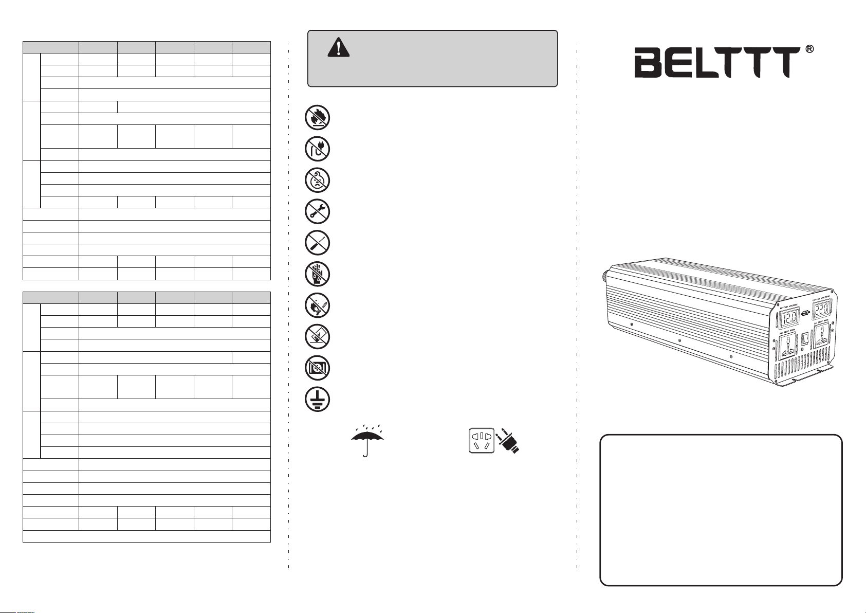
Product detail parameters
This series of pure sine wave inverter is suitable for:
Household appliances: TV, refrigerator, freezer, washing machine, air conditioner, power
amplifier, induction cooker, electric fan, electric cooker Lamps and lanterns, AV equipment......
Power tools: electric drills, pumps, cutting machines, motors, hand mills......
Office equipment: computers, printers, copiers, fax machines, network equipment......
On-board equipment:inverter can be connected to the car capacitor, suitable for all kinds
of on-board appliances.
Pure Sine Wave
Inverter Manual
To ensure reliable service, the inverter must be used properly.
Please read the instruction manual before use. Particular
attention should be paid to the warning and attention of this
brochure. Caution for certain conditions and practices that may
cause damage to the inverter. Make clear warning statements
about certain conditions and practices that may cause bodily
harm. Please read all instructions before using the inverter. 1
Please read this instruction manual carefully so that it can be
used correctly. Remember to read the "safety precautions"
section before you use it to make sure it's safe to use. After
reading the instructions, please complete the warranty card for
safekeeping, to keep on for reference. 1
Power Inverter
Solar Power Generation System
To avoid harm to you and others, here are
some of the following security considerations.
Be sure to follow the meanings of the various
flags. See the following.
WARNING
Inammable gas
●When connected to a battery, sparks are produced. Make sure there is no ammable
gas before connecting.
●The battery will produce ammable gas when charging and discharging. It should be
well ventilated and should not be stored in other places where it is ammable
No parallel with city power
The output can not be paralleled with the power supply, it will damage the inverter and
cause the danger of electric shock。
Minors are prohibited from using them
Can not be used by minors, inverter output is high voltage, may lead to electric shock
risk。
No disassembly or assembly
Do not disassemble or modify the inverter without permission. Unauthorized removal
or modication of the inverter may result in a safety accident such as a malfunction,
re or electric shock。
Bar contacts are prohibited
Do not place bars or other metal objects at the opening or socket of the inverter. This
may touch the internal parts and cause electric shock and inverter damage
Keep away from re and high temperatures
Fire and explosion can occur in inverter and battery when running in ame and high
temperature region。
Wet hands, do not touch
Do not touch the body and plug with wet hands, which may cause electric shock and
personal safety
No throwing
Bumping the inverter can cause damage and other safety hazards.
Medical equipment disabled
This inverter has not been tested and can not be used in medical equipment
Moisture proof and waterproof
Please pay attention to moisture proof
and waterproof. The inverter may cause
short circuit, re and electric shock due
to humidity or water inow。
Please insert completely
Please insert the load device plug into
the inverter socket completely. If the
plug is fully inserted at the end, it may
lead to electric shock and overheating,
and even cause a re accident. Do not
use damaged plugs, power outlets,
electrical wires。
Product characteristics
●The inverter is equipped with perfect protection circuit. Provide safe
automatic shutdown function, including overload protection, input
high-low voltage protection, to prevent damage to your inverter;
●The inverter has advanced anti-interference technology, fully functional
protection circuit and soft start circuit, convenient operation mode;
●modify the string wave output, inverter provides AC, USBoutput interface;
●instantaneous power up to 1000W, efficiency as high as 94%.
Please connect the ground wire.
In order to ensure the safety of use, please connect the ground wire.
BEP150S
150W
300W
50Hz / 60Hz(Optional)
12V / 24V / 48V(Optional)
12V / 24V / 48V(Optional)
10-15V(12V) / 20-30V(24V) / 40-60V(48V)
12V / 24V
(Optional)
12V / 24V
(Optional)
0.6A(12V)
0.3A(24V)
0.6A(12V)
0.3A(24V)
0.8A(12V)
0.6A(24V)
0.3A(48V)
0.8A(12V)
0.6A(24V)
0.3A(48V)
0.8A(12V)
0.6A(24V)
0.3A(48V)
Pure Sine Wave
5V / 500mA
High temperature protection、Shortcircuit Protection、Overload Protection
High temperature protection、Shortcircuit Protection、Overload Protection
160*95*55 172*150*58 260*150*78
309*180*172
262*150*76
Smart fan,Automatic startup of high temperature and load
Smart fan,Automatic startup of high temperature and load
Temperature 0℃~40℃@100%load, Humidity 20%~90%RH,No refrigeration
Temperature 0℃~40℃@100%load, Humidity 20%~90%RH,No refrigeration
530 910 1700 1800 3050
YES
YES YES NO
NO
NO
300W
600W
500W
1000W
800W800W600W
1600W1200W
≥90%
11(12V) / 21V(24V) / 42V(48V)
10V±0.5V(12V) / 20V±0.5V21V(24V) / 40V±0.5V(48V)
15V±0.5V(12V) / 30V±0.5V21V(24V) / 60V±0.5V(48V)
Rated Power
Peak Power
Frequency
Output
Input
Battery
input
protection
WaveForm
Battery
Voltage
Voltage
Range
Low Voltage Alarm
Battery low
voltage protection
Battery high
voltage protection
Battery reverse
polarity protection
Other protection
USB
FAN
Operating
environment
Size(mm)
Weight(g)
Efficiency
No load
Current
M O D E L
BEP300A
BEP500SA
BEP800SBEP600S
0.8A(12V)
0.6A(24V)
0.3A(48V)
367*150*76
2750
1000W
2000W
BEP1000S
10-15V(12V) / 20-30V(24V) / 40-60V(48V)
3.8A(12V)
2.0A(24V)
1.2A(48V)
2.5A(24V)
1.4A(48V)
1.8A(12V)
1.0A(24V)
0.5A(48V)
3.0A(12V)
1.5A(24V)
0.8A(48V)
5V / 500mA
585*180*167
452*150*142 454*180*142 529*180*142
4000 4900 6020 8000
Remarks:Please select the corresponding parameters according to the
≥90%
11(12V) / 21V(24V) / 42V(48V)
10V±0.5V(12V) / 20V±0.5V(24V) / 40V±0.5V(48V)
15V±0.5V(12V) / 30V±0.5V(24V) / 60V±0.5V(48V)
BEP1500S
1500W
3000W
2000W
4000W
3000W
6000W
5000W
10000W
BEP2000S BEP3000S BEP5000S
Pure sine wave
Performance introduction
An inverter is a power supply that conver ts direct current (batteries, solar cells, wind turbines, etc.)
into alternating current. Because of the high frequency inverter used in power conversion
technology, ferrite transformer to replace the old bulky silicon steel transformer. This is why the
inverter of our company is lighter weight and less bulky than other inverters that have similar rated
power. When the inver ter works in the inverter mode, the output waveform is modified sine wave. It
is a practical wave which waveform characteristic is similar to pure sine wave. This waveform is most
suitable for linear load and switching power supply of electronic equipment, such as light bulbs, rice
cookers, energy saving lamps, etc.. It can also be applied to inductive loads, such as transformers,
motors, etc.
The correct value of the modified sine wave for inverter output is 220V, which is the same as the
standard home power supply. Most AC voltmeters (digital and analog) use sensitive averaged
waveforms instead of RMS values.
Their calibration is set at RMS
voltage, which is used to measure
pure waves. Using them to
measure the output voltage of
the inverter, it is possible to
detect a low voltage 20V-30V. In
order to measure accurately,
please use the voltmeter which
can measure the effective value.
Using environment
In order to achieve the best use effect, please put the inverter in the surface of the smooth place,
such as the ground, the floor of the car, or other solid surface. Let the inverter power line can be
fixed easily. The working place should meet the following standards:
1.Do not allow the inverter to contact with water or other liquid to keep the inverter away from
moisture or water.
2.In a cool environment, the temperature is 0 degrees (without condensation) to 40 degrees. Don't
put the inverter next to the heating vents or other heating devices. Keep the inver ter out of the
sun as much as possible.
3.Keeping the ventilation and the absence of obstructions around it ensures that air is free to
circulate. When the inverter is working, do not put something on the inverter. The inverter fan is
used to help dissipate the heat.
4.Be careful not to use inverters near flammable materials or places where flammable gases can be
gathered.
5.The batter y not only provides a dc voltage of 11V to 15V, but also provides sufficient current to
run the load. The power supply should be a good battery full of electricity. To estimate roughly
the current required for a load, it can be estimated by dividing the power of the load by 10.
Continuous frequently open and close inverters can cause damage.
Non-professional technicians, do not open inverter shell
Rated current and actual use of equipment
The nominal current or power of most power tools, household appliances and video and audio
equipment is much smaller than the nominal power range of the inverter, but overload protection
occurs when they are started. Inverter is the most easy to drive resistive load or switching power
supply load. Because the resistive load is a linear load, it can work full load. Such as electric stove,
rice cooker, LCD TV and other equipment.
Some audio-visual equipment and electric tools to a greater level than resistive load power can
work normally, such as asynchronous motor, CRT TV, compressor, water pump etc. 2 to 6 times the
working current is required to start. The ability to run specific loads is subject to test.
Warming
Warming
Normally the fuse will not burn out unless serious circuit failure occurs.
When the inverter fails, please do not try to repair it yourself. Please
contact a professional technician to deal with the machine, there will be
high voltage electric shock hazard.
Common problem
Electric tools and microwave ovens cannot start
Carefully read the information on each power tool and accurately determine the input
power of the tool. Whether the output power is enough to run the tools and microwave
ovens, remember that power tools may need 2 to 6 times power requirements.
Television interference
The inverter has little interference with the television signal. However, in some cases,
some disturbances are still visible, especially when the television signal is weak.
Please try the following methods:
1.Try to keep the inverter away from the TV antenna or lengthen the TV antenna cable;
2. Adjust the direction of the inverter.
3.Ensure that the antenna provides strong signal strength to the TV set, and use high
quality antenna cable with good shielding effect.
4.When you watch TV, do not run high power electrical equipment or tools.
5.There is no way to completely disappear some of the old TV interference.
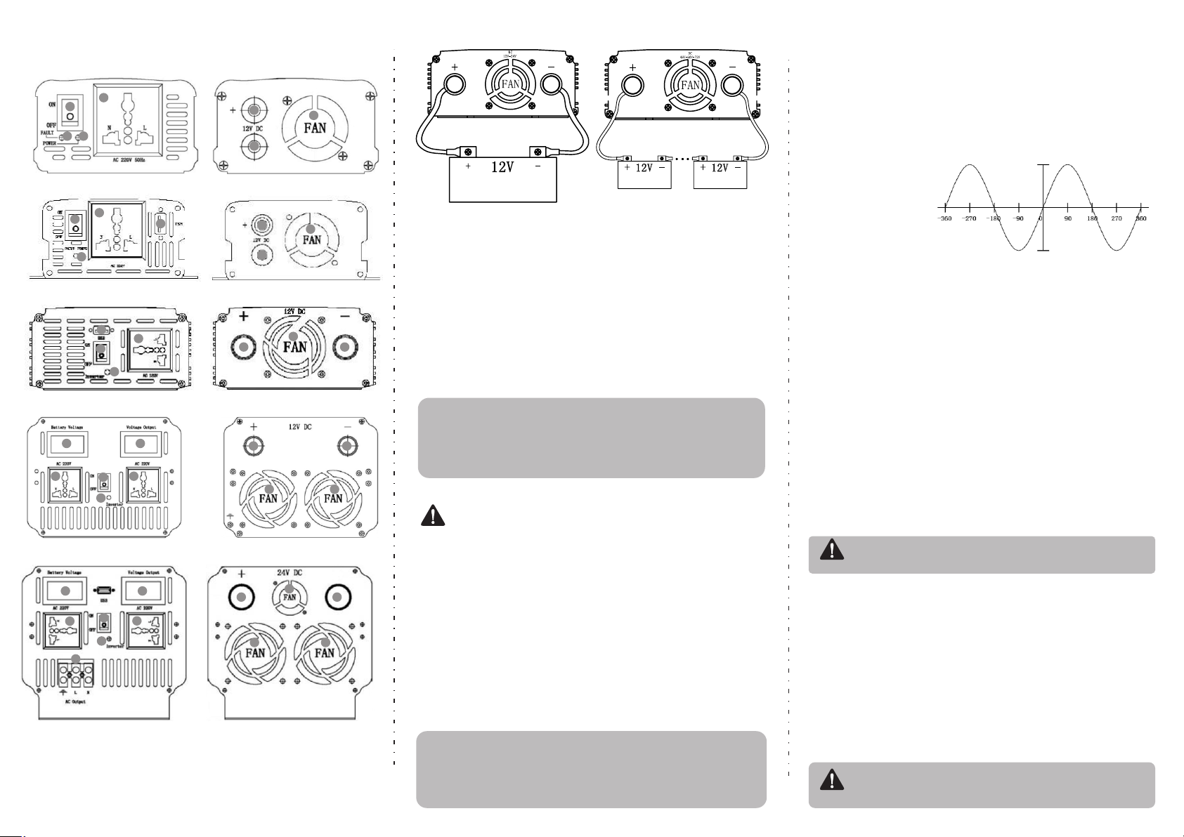
1.Wiring diagram is only for basic reference, please contact professional technical
personnel for actual installation.
One or more batteries can be used in inverters. One or more batteries can be used in
inverters. It's better to use 150AH or batteries with bigger capacity.
2.Since it may be necessary to connect the batter y for these operations, make sure there is no
flammable gas around before connecting.
Connect the inverter and the battery with the cables supplied with the inverter (excluding the
high-power mode cable). The red cable is connected to the red terminal of the inver ter input
terminal and the positive terminal of the batter y. The black cable is connected to the inverter Input
terminal black and battery negative. Please ensure that all cables are stable and reliable.Improper
connection may result in overheating of the cable, damage to terminals and lugs. At the same time
will cut down the batter y power supply time. Turn the inverter mode to ON, if your battery is fully
charged, the light of inverter will display green. The inverter is protected if the light displays red,
so tr y to solve it before using.(Check whether the battery voltage is too high or too low, the
inverter output is overload or short circuit)。
The power source for the 12V inverter can be used with a 12V battery or several 12V batteries in
parallel to increase the battery's power supply time.
3.Inverter must be connected to the same nominal voltage of the battery, 12V inverter
connected to the 12V battery, 24V inverter connected to the 24V batter y
4.Before you plug in all your power devices, make sure all devices are shut down.
Turn on the inverter mode switch, the POWER on the edge of the LED emits green light, and then
you can open your device one by one, if your device is not overloaded, now can work properly. If
LED glows red, it's overloaded .You need to reduce load restart to work.
Refer to the above connection diagram
1.First turn off the power switch of the inverter.
2.U se a black DC cable to connect the negative terminal of the battery
to the black terminal of the inverter.
3.C onnect the positive terminal of the battery to the red terminal of the
inverter with a red DC cable.
4.Plug the power supply plug of the power equipment into the output
socket of the inverter.
5.O pen the inverter power switch can be used.
Disassembly steps:
1. First turn off the power switch of the inverter;
2.Pull out the power plug of the load.
3.R emove the red DC cable;
4.Remove the black DC cable
For example, when the power of an AC load is 100W, the current
supplied by the power supply must be 100/10=10A. In the need of a
larger current, you can use several batteries in parallel to use. The most
important thing is to ensure that there is enough cross-sectional area
of the connecting cable. This manual does not list all battery pack
types. The battery's charging and battery configuration belong to
another professional categor y.
24V-36V-48V-72V
Connection diagram
12V Connection diagram
1、Power switch
2、AC output socket
3、Power indicator
4、Status indicator
5、USB Interface
6、Positive(red)
Pure sine wave inverter front and rear panel diagram
BEP150S Panel diagram
BEP300A/500SA Panel diagram
BEP1000S Panel diagram
BEP800S/1500S/2000S/3000S Panel diagram
BEP5000S Panel diagram
The product panel is for reference only.Please refer to the actual product.
Install the connection step:
●.In the installation of connecting cables should use a suitable cable, such as 220V output
cable is too long or the wire cross-sectional area is too small, there will be a lot of power
loss in the cable, the load side of the performance of small power, low voltage.
●.Batteries and inverter connection cable is not standardized, the cable is too long, the
cross-sectional area is too small, bad connection parts, will cause a lot of power loss.
Performance for the lack of output power, the battery voltage is too low, short working
hours, and even turn on the alarm does not work. At the same time the cable should be
waterproof, dielectric strength must meet the requirements of the use of the environment.
Installation method
12V Connection diagram
Battery
24V-36V-48V-72V
Connection diagram
Battery Battery
1
1
1
1
1
2
2
2
2
2
2
2
3
4
6
6
6
6
6
7
7
7
7
7
8
8
8
8
8
8
8
8
11
11
11
11
5
5
910
910
12
7、Negative(black)
8、Cooling fan
9、Voltage input monitor
10、Voltage output monitor
11、Double color status indicator
12、AC output interface
Warming

Pure sine wave inverter
CATALOGUE
User Manual
1. Safety Cautions -------------------------------------------------------------------------- 1
2. Product introduction--------------------------------------------------------------------- 1
2.1 Features ----------------------------------------------------------------------------- 1
2.2 Main Specifications --------------------------------------------------------------- 2
3. Panel description ----------------------------------------------------------------------- 2
3.1 Front Panel Description --------------------------------------------------------- 2
3.2 Front Panel Diagram ------------------------------------------------------------- 3
3.3 Indications of LED signals of the front panel ------------------------------- 3
3.4 Rear Panel Description ---------------------------------------------------------- 3
4. Settings of lnitial Output Voltage,Frequency,Standby Sacing Mode ------- 3
4.1 lnstruction of lnitial Factory Setting ------------------------------------------- 3
5. Protection Functions ------------------------------------------------------------------- 4
5.1 lnput Protection -------------------------------------------------------------------- 4
5.2 Output Protection ----------------------------------------------------------------- 4
5.3 lnstruction of Fault Signal ------------------------------------------------------- 4
6. lnstallation and Wiring ----------------------------------------------------------------- 5
6.1 Battery Wire ------------------------------------------------------------------------ 5
6.2 Battery Pack Recommendation ----------------------------------------------- 5
6.3 lnstallation Requirements ------------------------------------------------------- 6
6.4 Fixing Recommendation -------------------------------------------------------- 6
6.5 Reference Diagram of Setup -------------------------------------------------- 7
7. Troubleshooting -------------------------------------------------------------------------- 7
8. Cautions for the Electrical Load ----------------------------------------------------- 7
9. Warranty ----------------------------------------------------------------------------------- 7
3.2Front Panel Diagram
3.3 Indications of LED signals of the front panel
Status LED (Status LED): that is in the work mode
LED Display
State mode
GREEN
Normal
ORANGE
Standby Saving Mode
RED
Abnormal/Protection
When display abnormal,please refer to the instruction 5.2,5.3 or 7.of the manual to troublesh
Battery LED:Display the remaining capacity of the external batteries.
LED Display
STATE MODEL
Indication of 4 red LEDs
Battery =25%-50%-75%-100%
LOAD LED: Display the current capacity
LED Display
STATE MODEL
Indication of 4 red LEDs
Battery =25%-50%-75%-100%
3.4 Rear Panel Description
(1)Battery input Terminals(+)(-) (2)Air Vents(Fan) (3)Earth terminal of the chassis(FG)
4. Settings of Initial Output Voltage, Frequency,Standby Saving Mode
4.1 Instruction of Initial Factory Setting
(1)Factory Setting is 220Vac/50Hz or 110Vac/60Hz
(2)Set the Standby Saving Mode enabled(Not in use)
-3-
1
2
3
4
Fault
Power
ON
OFF
FAN
1
2
3
1. Safety Precautions (Please read this manual carefully before installing)
The machine contains high voltage with a potential hazard, if abnormal must be handled
by qualified technical personnel, do not open the Inverter cover.
Do not place Inverter in a humid environment and near water.
Do not place Inverter in a high-temperature environment, direct sunlight or near fire.
Replace the battery, please use the same brand and the same type of battery equipment,
is strictly prohibited using different brands or different capacity batteries at the same time use.
Do not keep the battery or battery near the fire source, or explode wounding.
Keep the Inverter before or after the air intake or exhaust (please keep at least 15cm or more).
Do not stack other items on the Inverter cabinet.
Warning: The battery will increase with the use of life and aging problems,
once the battery aging, the need for professionals to do the replacement or
treatment, or the battery may be due to leakage and other hazards caused by
the proposed annual maintenance of the battery on a regular basis.
No Disassembling No Humidity No Fire or High
Temperature
Don’t pile
Up Sundries
Keep Ventilation
2. Product Introduction
The off-grid inverter series for the digital CPU control, DC / AC converter,
the use of battery pack to provide energy conversion to AC voltage output.
With a sinusoidal waveform output, long-term work in the 0% -100% load state.
Its instantaneous power of more than 1 times, for inductive, capacitive load and other different load types.
Applications include computers, communications, yachts, SUV, home recreation equipment, motors, power
tools, industrial control equipment, various types of audio and video appliances and other applications.
2.1 Features
Sine wave output (THD <3%)
Highest efficiency output up to 91%
Full LED display working status
Too low battery capacity warning
Full digital control tips
The product complies with CE/FCC/LVD/ROSEspecifications
Can be applied to most AC input products
One-year free product maintenance and warranty
-1-
-2-
No Load
Current Draw
Protection
See the technical specifications
Overcurrent protection, battery reverse protection (built-in fuse) battery is too low warning and power protection
2.2 Main Specifications
40V-60V
91%
8.2A
16A
27A
41A
55A
68A
82A
109A
137A
165A
INPUT
OUTPUT
20V-30V
90%
17A
33A
55A
83A
111A
138A
167A
Factory Setting: 110V AC±3V
Through settings: 110/115/120V AC
60±0.5Hz
Model
Power
Voltage
Frequency
Waveform
Protection
PS300W PS600W PS1000W PS1500W PS2000W PS2500W
PS3000W PS4000W PS5000W PS6000W
0% -100% State (continuous use) - (120% - 150% = 10S) - (≤150% = 2S)
Factory Setting: 220V AC±3V
Through settings: 220/230/240V AC
50±0.5Hz
Rated power input, pure sine wave (THD <3%)
shoet-cireuit ptoteclion,over-load protection,
Battery
Voltage
Efficiency
DC
Current
Machine
Model
10.5V-15V
89%
PS300W Current
PS600W Current
PS1000W Current
PS1500W Current
PS2000W Current
PS2500W Current
PS3000W Current
PS4000W Current
PS5000W Current
PS6000W Current
32A
64A
107A
161A
214A
268A
321A
428A
535A
642A
222A
277A
333A
3. Panel Description
3.1 Front panel description
⑷ LED lights: Show Inverter working status, battery capacity, the use of load and abnormal
status warning.
⑶ air into the air hole: for Inverter cooling stable work, to maintain a smooth ventilation,
to ensure product life.
⑴POWER ON / OFF switch: switch if the switch in the ON position, then Inverter boot.
⑵ AC Outout output socket: the use of the needs of the region, with a variety of different
forms of socket for users to choose.
super-charge protection,over-temperature protection

-4-
5.Protection Functions
5.1 Input Protection
⑴ battery polarity reverse polarity protection: When the battery input reverse, Inverter internal or external
fuse will be blown, Inverter should be returned to the original maintenance. (For easy replacement: fuse
external, random with a ready-made fuse such as the user accidentally reverse, please open the FUSE
cover to replace the randomly prepared fuse)
⑵battery low voltage protection: When the battery voltage is lower than the specification value, Inverter
will automatically turn off the AC output and alarm 3 sound failure light long.
⑶battery high voltage protection: When the battery voltage is higher than the specification value, Inverter
will automatically turn off the AC output and alarm 4 sound failure light long.
WARNING: When using this series of Inverter, enter the battery pack, the voltage condition is
configured for normal operating voltage(The voltage marked by the specification).
If the configuration voltage is too low (such as 24V models with 12V input), then Inverter
will not boot properly.
If the configuration voltage is too high (such as 24V models with 48V input), then Inverter
will be destructive damage.
5.2 Output Protection
If an abnormality occurs, the unit will display a fault message lamp (see Table 5.3) for troubleshooting reference.
⑴over-temperature protection (OPT): When Inverter internal temperature is too high (70 degrees), will occur OTP
protection, and alarm 5 sound prompt (continuous alarm) fault LED light long, when the temperature dropped to
60 degrees, automatic recovery normal status.
⑵AC output abnormal protection: When Inverter AC output voltage is high or low, the need to start the new.
⑶AC output short circuit protection: When the Inverter output occurs when the short circuit or load surge from
the new start, remove the fault (or fault load) automatic recovery or manual recovery.
⑷battery voltage abnormal protection: when the battery voltage is too high or too low occurs, if the battery
voltage rises to the safe voltage range Inverter will automatically start from the new.
⑸Output overload protection (OLP): When the load ≧120% and ≦145% when the embedded buzzer alarm 10S
continuous after the turn off AC output, panel FAUL indicator flashes (reset inverter switch recovery).
⑹Output overload protection (OLP): When the load ≧145% for 2S off AC output, panel FAUL indicator flashes
(reset inverter switch recovery).
Fault InformationBuzzer
1 beep
2 beep
3 beep
4 beep
5 beep
Continuous beep
Normal Startup:Green LED is on,shows the inverter is normal.
Undervoltage Protection:Red LED is on,
shows the battery voltage is too low or depleted
Undervoltage Warning:The storage battery voltage is running out.
Overvoltage Protection:RED LED is on,
shows the battery voltage is too high.
Inverter overload protection: 10S after closing AC output
(need to reset the inverter switch).
Overheat Protection:RED LED is on,
shows the interior of the inverter is overheat.
5.3 Instruction of Fault Signal
6.3 Installation Requirements
The machine weight should be taken into consideration when fixing the machine, and avoid high
temperature and high pressure environment,in order to guarantee a long service life.
The machine uses the built-in fan to force the air-cooled heat, need to keep the front and rear
ventilation openings, to avoid long-term operation in high temperature environment or overload
conditions to operate, in order to avoid the machine can not provide normal function operation or affect
the service life. (Recommended access to the outlet 15 cm, should not hinder the ventilation of the fault)
6.3 Installation Diagram
Inverter Air
Air
>15cm
>15cm
As shown in the figure, the body shell design to retain four fixed holes, the user can use the
reserved hole to be fixed. (Recommended horizontal fixed, and pay attention to whether the
ventilated ventilation is smooth)
-6-
6.4 Fixing Recommendation
6. Installation and Wiring
6.1 Battery cable:
wire length should be shortened, the following is not more than 1.5 meters for the principle,
and the choice of wire diameter required according to safety regulations, can carry the
current flow of the wire. Wiring too thin will cause the wire to overheat and even cause the
risk of ignition.Please refer to the following table 6-1 actual wiring, please find the dealer or
the original factory to ensure safety
Form 6-1 Wire Using recommendation
Rated Current
16A-25A
25A-32A
32A-40A
40A-60A
63A-80A
80A-100A
100A-125A
≥125A
2.5
4
6
10
16
25
35
50
AWG
12
10
8
6
4
2
1
0
Wire CSA(m㎡)
Safety Wiring Range
6.2 Battery Pack Recommendation
1. The battery pack is configured with the minimum safe start and full load discharge time.
Users can use this table to select a larger capacity (to meet the discharge time) to meet the
needs of the battery pack.
2. Inverter working time is under load conditions, how to determine the time of a battery work,
where the first description of the battery capacity, the battery is the time (AH) to nominal capacity.
Anshi (AH) means the maximum discharge capacity of the battery within 1 hour, such as a battery
nominal 20AH, which in 1 hour maximum output 20A current. We can use this value to count the
time it takes for a battery to drive a load.
The time that a battery needs to drive a load:
Battery capacity (AH) × battery voltage (V) × 0.8 × 0.9 ÷ load = working hours (hours)
3. Because the battery can not be fully discharged, so 20% can not discharge, because the battery
has a memory function, the electric light, the battery is useless, so the maximum power to multiply 0.8
This is the actual power of the battery can work , In the battery can not put the photoelectric at the
same time the inverter also has the conversion efficiency of the problem, for the quasi-sine in general
efficiency of about 90%, so here selected 0.9, and battery capacity × battery voltage × 0.8 × 0.9, this
is the real inverse The total power that the transformer can do to the load.
The battery by the inverter to work on the load time:
For example:a 12V/60Ah Battery, a 220v/100w filament lamp
Working Time=12(V)×60(AH)×0.8×0.9÷100(W)=5.18(Hour)
Explanation:12V--Battery Voltage
60AH--Battery Vapacity
0.8--Battery Capacity
0.9--Inverter Convert Efficierncy
-5-
100(W)--The nominal power the bulb
5.18(Hour)--The working time that a 60AH battery works by the power supply of batteries ps,
there are some errors of the actual discharge time base on the conditions,lifetime,maintenance of batteries.
Solution: battery capacity (AH) × battery voltage (V) = battery can output the maximum power (W)
Working hours = battery capacity (AH) × battery voltage (V) × 0.8 × 0.9 ÷ load
-7-
6.5 Rerence Diagram of Setup
BATTERY
Inverter
LOAD
about 15cm
15
about 15cm
15
a 1.5 meter-long wire is recommended
wall or system FG
7. Troubleshooting
This series of inverter power supply for professional goods, due to improper use or modification, can
cause damage or electric shock hazard. Therefore, the company recommends that users according to
the following table after the basic inspection can not return to normal, please contact the dealer or return
to the original maintenance.
Fault state May cause the cause Suggest the method of lifting
AC
voltage
no output
DC voltage abnormality Check if the DC voltage (battery voltage) is too low or too high
Over temperature protection Check if the radiator vents are open or the temperature is too
high. Please use or lower the ambient temperature
Overload protection Check whether the load exceeds the rating or requires
large starting current,such as inductive or capacitive devices.
Short circuit protection Check whether the load exceeds the rating or short-circuited
battery is used for too
long or malfunctioning Replace battery
battery capacity is too small Confirm specifications recommend increasing battery capacity
Battery
discharge
Time is too
shortrt
8.Cautions for the Electrical Load
This series of inverter power supply can be used on most AC devices, and can be normal power supply.
But some special equipment applications, Inverter may not be able to start or work properly.
2) When the load device is capacitive or rectified (for example: switching or switching power supply), it is
recommended to put the device before the no-load or light load conditions, with Inverter after the start
of the load will slowly increase to ensure that Inverter can be smooth machine.
9.Warranty
In the normal use of the product to provide free repair service for 1 year, do not replace the parts or modify
or repair the product in any way, so as not to affect your enjoyment of the normal warranty service.
1) Motor load equipment due to its start will produce a great starting current (about 6-10 times the rated
current), pay attention to whether the instantaneous start power exceeds the Inverter maximum output
power specifications.
This manual suits for next models
9
Other BELTTT Inverter manuals


Popular Inverter manuals by other brands


Generac Power Systems
Generac Power Systems Air-cooled Recreational Vehicle Generator... owner's manual

EGO
EGO Power+ Nexus Escape PAD1500E Operator's manual

Simder
Simder SD-4050 MINI Operator's manual

SMA
SMA WINDY BOY 3300 installation guide

Sungrow
Sungrow SG110CX user manual

ARX
ARX Centre MIXX owner's manual