SCC SKY Series User manual

SCC SKY INVERTER Series
1000VA / 2000VA
OFF Grid Solar Home System
User Manual

TABLE OF CONTENT
1. Introduction…………………………………………………………………………………1
2. Important Safety Warning (Save These Instructions)…………………...1
3. Product Overview………………………………………………………………………...2
3.1 Top Panel……………………………………………………………………………………………………2
3.2 Rear Panel…………………………………………………………………………………………….........2
4. Installation…………………………………………………………………………………..3
4.1 Mounting the unit……………………………………………………………………………………….3
4.2 Connect to Utility and Charge………………………………………………………………………3
4.3 Connect to Solar Panel…………………………………………………………………………………4
4.4 PV Module Selection…………………………………………………………………………………….5
5. Operation…………………………………………………………………………………….6
5.1 Power ON/OFF…………………………………………………………………………………………...6
5.2 LED Indicators & Audible Alarm………………………………………………………………......6
5.3 LCD Display………………………………………………………………………………………………...6
5.4 LCD Setting…………………………………………………………………………………………………8
5.5 Display Setting………………………………………………………………………………………….10
5.6 Operating Mode Description……………………………………………………………………..11
5.7 Fault Reference Code…………………………………………………………………………………11
6. SPECIFICATION…………………………………………………………………………..12
7. TOUBLESHOOTING……………………………………………………………………..13

SCC SKY INVERTER User Manual
1
1. Introduction
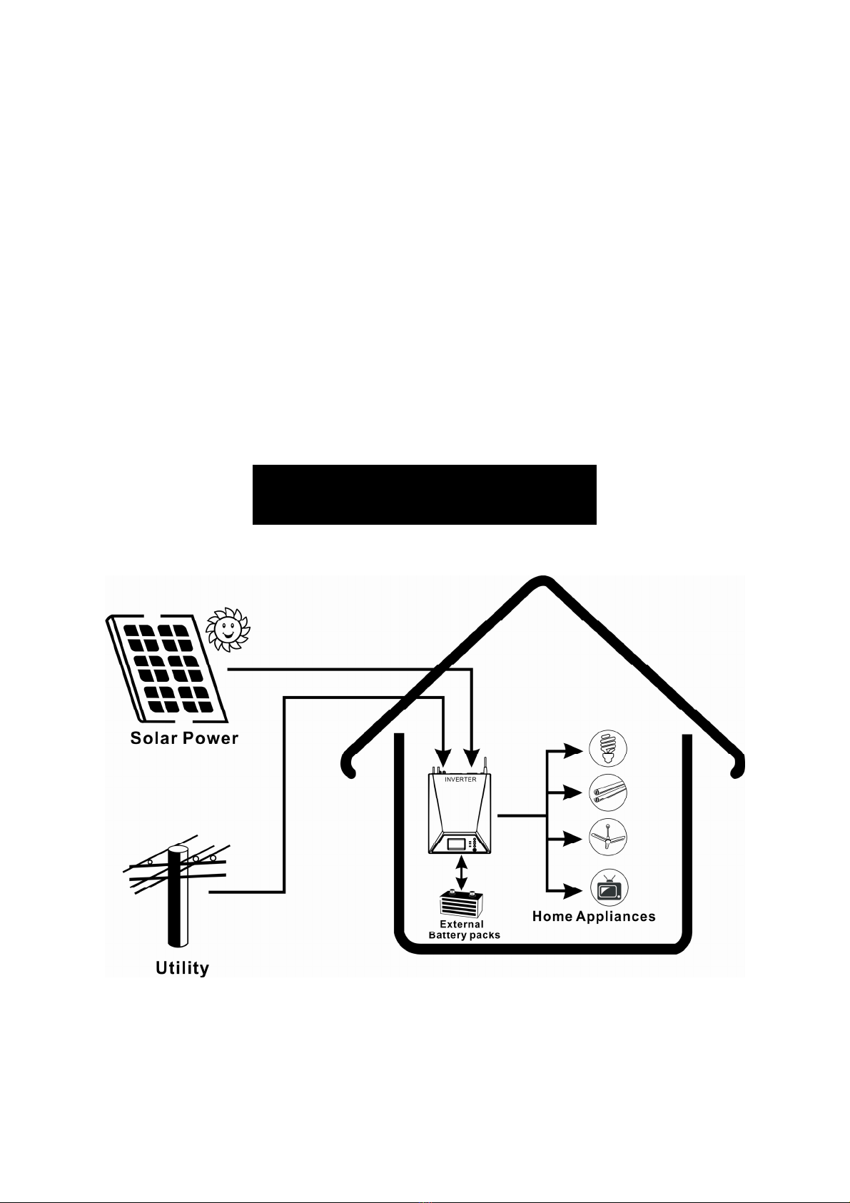
This is a DC-to-AC inverter with integrated solar battery charger, an energy-saving solution or an
automotive inverter (hereinafter referred to as “inverter”)
The inverter accepts input power source from AC mains (utility), battery, and PV (solar) string and
switches between various operation modes automatically depending on the operational conditions.
The PV (solar) string can be set as priority to supply the loads without consuming the power from AC
mains, as long as sufficient sunlight is present.
The battery can be charged by both AC mains and PV (solar) string with intelligent charging control.
Key features:
Built-in enhanced AC charger & solar charger controller up to 50A
Selectable input voltage ranges, charging priority setting, AC or solar power priority setting
Auto restart when AC recovery
User-friendly LCD and LED indications with setting function
With the environmental temperature control charge management
Rack design & wall-mounted design for flexible installation
Intelligent 3-stage charger control for efficient charging and preventing overcharge
Multiple protection: low battery alarm, low battery shutdown, over charge protection, overload protection,
over temperature protection, short circuit protection
Fan speed automatic adjust, Low noise
Battery Cut off point setting, Buzzer alarm ON/OFF setting
2. Important Safety Warning(Save These Instructions)
Before using the inverter, please read all instructions and cautionary markings on the unit, this
manual and the batteries.
Conventions used:
WARNING! Warnings identify conditions or practices that could result in personal injury.
CAUTION! Caution identify conditions or practices that could result in damaged to the unit or other
equipment connected.
General Precaution-
WARNIN G! The unit is designed for indoor use. Do not expose this unit to rain, snow or liquids of any
type.
WARNIN G! To reduce risk of injury, only use qualified batteries from qualified distributors or
manufactures. Any unqualified batteries may cause damage and injury. Do not use old or overdue batteries.
Please check the battery type and date code before installation to avoid damage and injury.
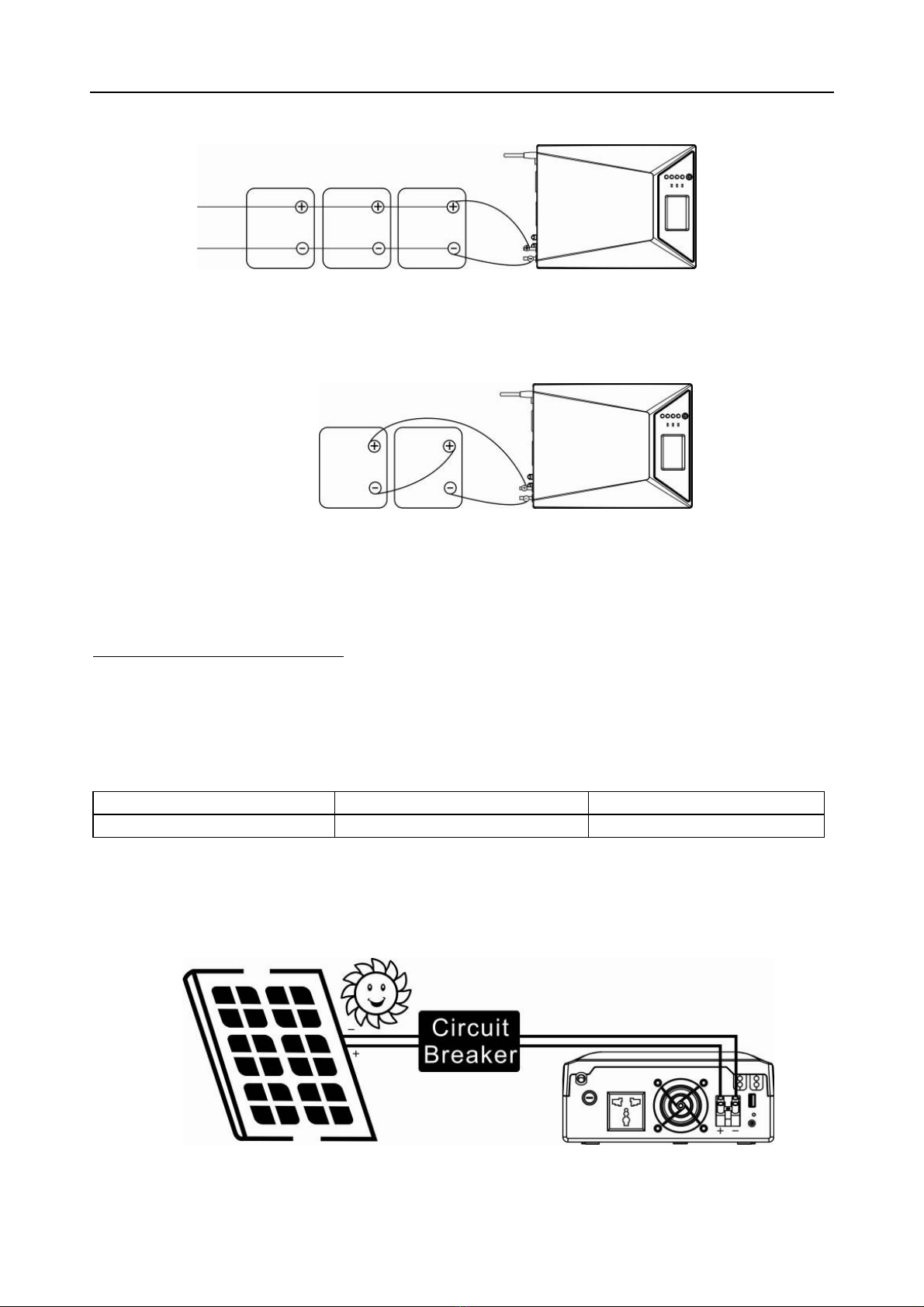
WARNIN G! It’s very important for system safety and efficient operation to use appropriate external
battery cable. To reduce risk of injury, external battery cables should be UL certified and rated for 75℃ or
higher. And do not use copper cables less than 10AWG.
WARNIN G! Do not disassemble the inverter. Contact with the qualified service center when service or
repair is required.
WARNIN G! Provide ventilation to outdoors from the battery compartment. The battery enclosure should
be designed to prevent accumulation and concentration of hydrogen gas at the top of the compartment.
WARNIN G! Use insulated tools to reduce the chance of short-circuit when installing or working with the
inverter, the batteries, or other equipments attached to this unit.
WARNIN G! For battery installation and maintenance, read the battery manufacture’s installation and
maintenance instructions prior to operating.
Personnel Precaution-
WARNIN G! Careful to reduce the risk or dropping a metal tool on the batteries. It could spark or short circuit
the batteries and could cause an explosion.
WARNIN G! Remove personal metal items such as rings, bracelets, necklaces, and watches when working with
batteries. Batteries can produce a short circuit current high enough to make metal melt, and could cause
severe burns.
WARNIN G! Avoid touching eyes while working near batteries.
WARNIN G! Have plenty of fresh water and soap nearby in case battery acid contacts skin, clothing, or eyes.
WARNIN G! Never smoke or allow a spark or flame in vicinity of a battery.

SCC SKY INVERTER User Manual
2
3. Product Overview
3.1 Top Panel
3.2 Rear Panel
①Power ON/OFF button
②Setting function button
③LCD
④LED indicator
①AC input
②Input circuit fuse
③AC output receptacle
④Battery input wires
⑤PV input terminal
⑥Cooling fan
⑦USB charger for option

SCC SKY INVERTER User Manual
3
4. Installation
NOTE: Before installation, please inspect the unit. Be sure that nothing inside the
package is damaged.
4.2 Connect to Utility and Charge
Plug in the AC input cord to the wall outlet. The unit will automatically charge the
connected external battery even though the unit is off.
Connect External Battery
Step 1- Take away the cover of external battery terminal.
Step 2- Following battery polarity guide printed near the battery terminal!
Place the external battery cable ring terminal over the battery terminal,
RED cable to the positive terminal (+);
BLACK cable to the negative terminal (-).
Step 3- Connect battery cables to the external batteries.
Note: For the user operation safety, we strongly recommend that you should use tapes
to isolate the battery terminals before you start to operate the unit.
1) Single battery connection (Refer to Fig. 2): When using a single battery, its voltage
must be equal to the Nominal DC Voltage of the unit (see below Table 1)
Fig. 2
4.1 Mounting the unit
The unit ONLY can be mounted vertically
to a wall surface.
Please follow below steps:
1. Turn off the unit before mounting,
2. Select an appropriate mounting location.
Use a horizontal line and the length of the
line must be 172 mm and mark the two
ends on the wall.(See Fig. 1)
3. Drill two marks by screws.
4. Mount the unit by positioning the
key-hole slots over the mounting screws.
Fig. 1
Model
Nominal Battery
Voltage
SCC SKY
INVERTER 1000
12Vdc
SCC SKY
INVERTER 2000
24Vdc

SCC SKY INVERTER User Manual
4
2) Multiple batteries in parallel connection(Refer to Fig. 3): Each battery's voltage
must be equal to the Nominal DC Voltage of the unit.
Fig. 3 12V
3) Multiple batteries in series connection(Refer to Fig. 4): All batteries must be
equal in voltage and amp hour capacity. The sum of their voltages must be equal to the
nominal DC Voltage of the unit.
Fig. 4 24V
Step 4- Make sure to connect the polarity of battery side and the unit correctly.
Positive pole (Red) of battery to the positive terminal (+) of the unit.
Negative pole (Black) of battery to the negative terminal (-) of the uni
4.3 Connect to Solar Panel
CAUTION: Before connecting to PV modules, please install separately a DC circuit
breaker between inverter and PV modules.
WARNING! All wiring must be performed by a qualified personnel.
WARNING! It’s very important for system safety and efficient operation to use
appropriate cable for PV module connection. To reduce risk of injury, please use the
proper recommended cable size as below.
Typical Amperage Gauge Torque Value
50A 8 AWG 1.4~1.6 Nm
Step 1- Connect one cable to the positive (+) pole of solar panel and solar charger
positive (+) terminal.
Step 2- Connect the other cable to the negative (-) pole of solar panel and solar charger
negative (-) terminal.
Solar Panel Connection

SCC SKY INVERTER User Manual
5
4.4 PV Module Selection
The following parameters can be found in each PV panel’s specification, when selecting
proper PV modules, please be sure to consider below requirements first:
·Voc: Open Circuit Voltage (V) ·Pmax: Maximum Power (W)
·Vmpp: Max. Power Voltage (V) ·Immp: Max. Power Current (A)
·Isc: Short Circuit Current (A)
1. Open circuit Voltage (Voc) of PV modules not exceeds max. PV array open circuit voltage of inverter.
Model SCC SKY INVERTER 1000 SCC SKY INVERTER 2000
MAX. INPUT POWER 600W 1200W
CHARGING CURRENT (PWM) 50Amp
System DC Voltage 12Vdc 24Vdc
OPTIMAL WORK VOLTAGE RANGE 15V~18V 30V~32V
MAX. PV INPUT VOLTAGE 40V 60V
2. Max. Power Voltage (Vmpp) of PV modules should be close to Best Vmp of inverter or within Vmp
range to get best performance. If one PV module can’t meet this requirement, it’s necessary to have
several PV modules series connection. Refer to below table.
Model Best Vmp Vmp range
SCC SKY INVERTER 1000 15Vdc 15V~18V
SCC SKY INVERTER 2000 30Vdc 30V~32V
Note: Best Vmp: panel max power point voltage.
The PV charging efficiency if maximized while PV system voltage is close to Best Vmp.
Maximum PV module numbers in Series PV module numbers in parallel
Vmpp of PV module * X pcs ≒ Best Vmp of
Inverter or Vmp range. Max. charging current of inverter / Impp
Total PV module numbers = maximum PV module number in series * PV module number in parallel
Example 1: SCC SKY INVERTER 1000
After considering Voc PV module not exceeds 40Vdc and max. Vmpp of PV module close to 15Vdc or within
15Vdc~18Vdc, we can choose PV module with below specification.
Maximum Power (Pmax) 84W Max. PV module number in series
17.22 × 1 ≒ 15~18 →1
Max. Power Voltage Vmpp(V) 17.22V
Max. Power Current Impp(A) 4.85A PV module number in parallel : 50A/4.85A=10.31 ≈ 10
Total PV module numbers : 1 × 10 = 10
Open Circuit Voltage Voc(V) 21.97V
Short Circuit Current Isc(A) 5.23A
Maximum PV module numbers in Series: 1
PV module numbers in parallel: 10
Total PV module numbers: 1 × 10 = 10
Example 2: SCC SKY INVERTER 2000
After considering Voc PV module not exceeds 60Vdc and max. Vmpp of PV module close to 30Vdc or within
30Vdc~32Vdc, we can choose PV module with below specification.
Maximum Power (Pmax) 255W Max. PV module number in series
30.65 × 1 ≒ 30~32 →1
Max. Power Voltage Vmpp(V) 30.65V
Max. Power Current Impp(A) 8.31A PV module number in parallel : 50A/8.31A=6.02 ≈ 6
Total PV module numbers : 1 × 6 = 6
Open Circuit Voltage Voc(V) 37.93V
Short Circuit Current Isc(A) 8.62A
Maximum PV module numbers in Series: 1
PV module numbers in parallel: 6
Total PV module numbers: 1 × 6 = 6

SCC SKY INVERTER User Manual
6
5. Operation
5.1 Power ON/OFF
Once the inverter has been properly installed, press the power switch to turn on the unit. The unit will
work automatically in line mode or inverter mode according to input utility power's status. When press
the power switch again, the unit will be turned off.
5.2 LED Indicators & Audible Alarms
There are three indicators (Green/ Yellow / Red) in the front panel of the unit.
Indicator Status Alarm
Green LED
lighting Line mode and battery fully charged Off
flashing every 2 sec Battery charging at power on Off
flashing every 5 sec Battery charging at power off Off
flashing every 10 sec Battery fully charged at power off Off
Yel low LED
lighting Battery mode Off
flashing every 5 sec Shutdown mode Off
flashing every 1 sec Battery weak at battery mode Beep every sec
Red LED
lighting Fault mode Continuous
beep
flashing every sec The unit is overload Beep every 0.5
sec
flashing every 5 sec The unit is over charged Continuous
beep
5.3 LCD Display
Display Function
Input source information
Indicates the AC input
Indicates the PV input
Indicate input voltage, input frequency, PV voltage, Battery voltage ,
Charging current
Configuration Program and Fault Information
Indicates the setting programs.
Output Information
Indicate the output voltage, output frequency, Load percent, Load in
VA, Load in W
Battery Information
Indicate the Battery level by 0~10%, 10%~30%, 30%~55%,
55%~80%, 80%~100% in battery mode, charging status in line mode

SCC SKY INVERTER User Manual
7
Indicates the Battery voltage low.
Battery mode:
4 step: battery voltage ≥11.7V/23.4V the four bars are lighting.
3 step: battery voltage ≥11.1V/22.2V the first three bars are lighting.
2 step: battery voltage ≥10.6V/21.2V the first two bars are lighting.
1 step: battery voltage <10.6V/21.2V the first bar is lighting.
Line mode:
4 step: CV mode, battery voltage ≥13.0V/26.0V the four bars are lighting.
3 step: CC mode, battery voltage ≥14.0V/28.0V the first three bars are lighting, the fourth is flashing.
2 step: CC mode, battery voltage ≥13.5V/27.0V the first two bars are lighting, the others are flashing.
1 step: CC mode, battery voltage ≥13.0V/26.0V the first bar is lighting, the others are flashing.
0 step: CC mode, battery voltage <13.0V/26.0V all led bars flashing
Load Information
Indicates overload
4 step: ≥80% load level.
3 step: ≥55% load level.
2 step: ≥30% load level.
1 step: ≥10% load level.
Mode operation information
Line Mode
Backup Mode
Fault Mode
Indicates unit connect to the mains
Indicates unit connect to the PV panel
Indicates the utility charger circuit is working
Indicates the DC/AC inverter circuit is working
Mute operation
Indicates unit buzzer is disabled

SCC SKY INVERTER User Manual
8
5.4 LCD Setting
After pressing and holding “ENTER” button for 3 seconds, the unit will enter setting mode. Press
''UP/DOWN'' button to select setting programs. And then, press “ENTER" button to confirm the selection
or “ESC” button to exit.
If there is no button action during 60 seconds, setting mode will exit to normal display mode.
During shutdown process, the setting information can be stored in MCU, and it will be read out during
next start up.
Program Description Selectable option
00
AC input
voltage
range
selection
Wide(default)
If selected, acceptable AC input
voltage range will be within
90~280Vac.
Narrow
If selected, acceptable AC input
voltage range will be within
170~280Vac.
01
AC charging
current
selection
20A (default)
10A
02
Low DC
cut-off
voltage
setting
9.8V (default)
1000VA model: setting range
8.7~12.0Vdc, 0.1V /time.
19.6V(default)
2000VA model: setting range
17.5~24.0Vdc, 0.1V /time.
03
AC output
rating
voltage
selection
230V (default)
220V 240V
04
Output
source
priority
(utility or
solar first)
utility first(default)
Utility will provide power to the
loads as first priority.
Solar and battery energy will
Solar first
Solar energy provide power to the
loads as first priority.
If solar energy is not sufficient to

SCC SKY INVERTER User Manual
9
provide power to the loads only
when utility power is not
available.
power all connected loads, battery
energy will supply power the loads
at the same time.
Utility provides power to the loads
only when any one conditions
happens:
-Solar energy is not available.
-Battery voltage drops to low- level
warning voltage or the setting point
in program 06.
05
Solar
charging
current
selection
50A (default) 30A 10A
06
Setting
battery
voltage
point back
to utility
source
when
selecting
“solar first”
11.5V (default)
1000VA Model:
10.8~12.5Vdc, 0.2~0.3V/time.
23.0V (default)
2000VA Model:
21.8~25.1Vdc, 0.4~0.5V /time.
07
Setting
battery
voltage
point back
to battery
mode when
selecting
“solar first”
13.2V (default)
1000VA Model:
11.9~13.7Vdc, 0.2~0.3V/time.
26.4V (default)
2000VA Model:
23.8~27.5Vdc, 0.4~0.5V /time.
08
Buzzer
mute
control
ON (default)
OFF
09
Background
LED control
(for option)
ON (default)
OFF

SCC SKY INVERTER User Manual
10
5.5 Display Setting
The LCD display information will be switched in turns by pressing ''UP/DOWN'' key. The selectable
information is switched as below order: input voltage, output voltage, battery voltage, PV voltage, PV
charging current, load percentage, load in VA, load in Watt, CPU Version, rated capacity.
Selectable
information
LCD display
S e le c ta b le
information
LCD display
AC input voltage
/ AC output voltage
(Default Display Screen)
Load percentage
Battery voltage Load in VA
PV voltage Load in W
PV charging current
CPU version
/ Rated capacity

SCC SKY INVERTER User Manual
11
5.6 Operating Mode Description
Operation
Mode LCD Display
Standby
Mode
Charging by utility Charging by PV energy
Charging by utility and PV energy
Description: Utility input bypass to output, charger available
Note:*Standby Mode: The inverter is not turned on yet but at this time, the inverter can
charge battery with AC bypass output.
Line
Mode
Charging by utility Charging by PV energy
Charging by utility and PV energy
Description: The unit will provide output power from the mains. It will also charge the
battery at line mode.
Battery
Mode
Power from battery only
Power from battery and PV energy
Description: The unit will provide output power from battery and PV power.
5.7 Fault Reference Code
Fault
Code Fault Event Fault
Code Fault Event
00
Output voltage too high
01
Battery overcharge
02
Output short
03
Over load after alarm
04
Battery voltage too low
05
Fan failure

SCC SKY INVERTER User Manual
12
6. SPECIFICATION
CAPACITY ( VA/W) 1000VA/900W 2000VA/1600W
NOMINAL BATTERY VOLTAGE
(lead-acid battery) 12Vdc 24Vdc
LINE MODE
INPUT
Nominal Voltage 230Vac
Voltage Range 170~280Vac (Narrow Range)
90~280Vac (Wide Range)
Normal Frequecy 50Hz or 60Hz
OUTPUT Voltage 230Vac
Frequency / Waveform Following the Utility
TRANSFER TIME 20ms Typical
BACKUP MODE
OUTPUT
Voltage 230Vac (+10% / -18%)
Frequency 50Hz or 60Hz (Auto detection)
Waveform Simulated Sine Wave
PROTECTION Discharge, over-charged, over-loading,
over-temperature, short-circuit protection
BATTERY CHARGER (POWERED BY AC)
CHARGING ALGORITHM 3-step charging
AC CHARGING MODE 10A / 20A 10A / 20A
FLOATING CHARGGING VOLTAGE 13.75±0.25V 27.50±0.50V
OVERCHARGING VOLTAGE 15.30V 30.60V
SOLAR BATTERY CHARGER
MAX. INPUT POWER 600W 1200W
CHARGING CURRENT (PWM) 50Amp
System DC Voltage 12Vdc 24Vdc
OPTIMAL WORK VOLTAGE RANGE 15V~18V 30V~32V
MAX. PV INPUT VOLTAGE 40V 60V
MAX. PV INPUT CURRENT 50Amp
GENERAL
PHYSICAL Dimension (D*W*H) 316mm(D)*227mm(W)*92mm(H)
Net Weight (kg) 3.1 3.3
ENVIRONMENT
Operating Environment 0~50℃, 0%~90% relative humidity (non-condensing)
Storage Environment -15℃ to 55℃,0% to 90% humidity (non-condensing)
Noise Level Less than 50dB

SCC SKY INVERTER User Manual
13
7. TROUBLESHOOTING
Problem LED/LCD/Buzzer Possible Cause Solution
Utility power is
normal but the unit is
in battery mode.
Yellow LED is lighting or
flashing, Input voltage
displayed as 0 on the LCD.
AC input Power cord is not
connected well or Input
protector is tripped
Check if AC wiring is
connected well an AC
protector is tripped.
Green LED is lighting or
flashing, Input voltage
displayed normal on the
LCD.
Set “Solar first” as the
priority of output source.
Change output source
priority to Utility first
Backup time is short.
Battery low alarm issue
quickly.
Battery voltage is too low.
Charge the unit at least 8
hours.
Battery capacity is not full
even after charge the unit
for at least 8 hours.
Check the date code of the
battery. If the batteries are
too old, replace the batteries.
No display on the
front panel when the
utility power is
normal.
No LED/LCD display.
Battery is not connected
well.
Check if the external battery
cable and terminal are all
correct.
Battery defect. Replace the batteries.
Solar ok but Solar
charger doesn’t work.
PV voltage displayed as 0
on the LCD.
PV reverse polarity
protection.
Re-connect the PV terminals.
Buzzer beeps
continuously and red
LED is on.
Fault code 00 Output voltage too high Return to repair center.
Fault code 01 Battery overcharge Return to repair center.
Fault code 02
Output short / Over
temperature
Check if wiring is connected
well and remove abnormal
load, and make sure the unit
has adequate air flow.
Fault code 03 Over load after alarm Disconnect non-critical loads .
Fault code 04 Battery voltage too low Return to repair center.
Fault code 05 Fan failure Replace the fan.
If there is any abnormal situations occur, which doesn’t list above, please call the service people
immediately for professional examine.

SCC SKY INVERTER User Manual
14
DISPOSAL
In the event the product reaches the end of its service life, please contact the
local dealer for disposal instructions.
The product must not be disposed of with the
household waste.
Disposal of the product at the end of its service life shall be done accordance
with applicable disposal regulations for electronic waste.
This manual suits for next models
2
Table of contents