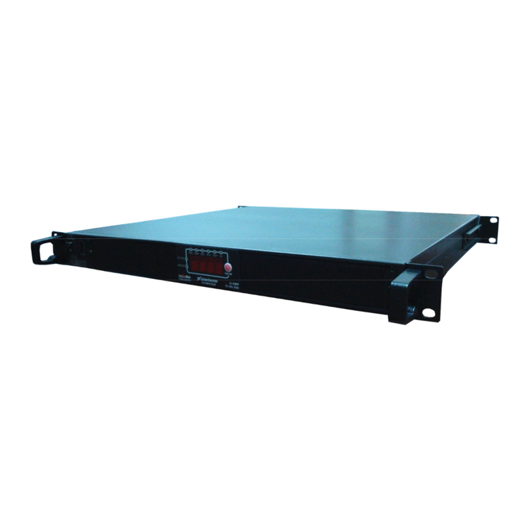
Asian Electron PIC2KVA Series User manual

1
Listof Contents
1. Features
1-1 Application 2
1-2 Electricalperformance 3
2. Introduction
2-1 Front paneloperations 4
2-2 Rear paneloperations 5
2-3 Installation 7
2-4 Quickhook up andtesting 7
2-5 AC safety grounding 9
2-6 Making DC wiring connections 10
2-7 Inverter operation 10
2-8 Coolingfanworkingcode 12
3. Maintenance 13
4. Troubleshootingguide 13
5. Warranty 14
6. Important safety striations
6-1 Generalsafetyprecautions 14
6-2 Precautions when working withbatteries 15
7. Appendices A
7-1 Dip switch 15
7-2 Tune VR 15

2
1.Features
nDigital display
nBattery charger inside
nAC Output frequency:50/60Hz switch
nRS 232 interface/ remotecontrol port / wire connection to PC
nAutomatic transfer between inverter power and incoming AC utility power
nWired remote control
nLoadingcontrolled cooling fan
nAdvanced microprocessor
nProtection : Input low voltage
Overload
Short circuit
Low batteryalarm
Input overvoltage
Over temperature
1-1 Utilities Application
1-1-1Power tools circular saws, drills, grinders,sanders, buffers,weedandhedge
trimmers,air compressors.
1-1-2Office equipment computers, printers,monitors, facsimilemachines, scanner.
1-1-3Householditems vacuum cleaners,fans,fluorescent and incandescent lights,
shavers,sewingmachines.
1-1-4Kitchenappliances microwave ovens,refrigerators andfreezers, coffee makers,
blenders, ice markers,toasters.
1-1-5Industrial equipment metalhalidelamp,high pressure sodium lamp.
1-1-6Home entertainment electronics television, VCRs,videogames, stereos, musical
instruments,satelliteequipment.

3
1-2 Electrical Performance
Specification Model
Item YK-
PIC30122KVA
YK-
PIC15242KVA
YK-
PIC08482KVA
YK-
PIC30122KVAE
YK-
PIC15242KVAE
YK-
PIC08482KVAE
Continuous Output
Power 2000W
Surge Rating 4000W
Input Voltage 12V 24V 48V 12V 24V 48V
Frequency 50/60Hz 0.05%( Switch Selectable)
Peak Output Current
35A 16A
Efficiency (fullload)
86% 88% 89% 87% 90% 92%
Output Waveform R LoadPureSine Wave < 3%THD
Output Voltage100/110/115/120V(Switch Selectable)RMS ±2%
200/220/230/240V(Switch Selectable) RMS ±2%
Stand byCurrent Draw
1.5W Power Saving Mode
Output Voltage
Adjustment VAC 100~120V (Tune VR) VAC 200~240V (Tune VR)
Input Voltage
Regulation 10-16VDC
20-32VDC
42-62 VDC
10-16 VDC 20-32 VDC 42-62 VDC
Protection Overload,ShortCircuit, ReversePolarity (Fuse), Over/UnderInput Voltage, Over
Temperature.
DigitalDisplay OVP、UVP、OTP 、OLP、VAC、AMP、WATT、VDC、TEMP、Hz
InterfaceControlPort
RS-232CWith BaudRate2400,4800,9600,19200 (Switch Selectable)
AC Input AC110V (90~130V) AC220V(180~260V)
AC Frequency (50Hz~ 60 Hz) +/- 3% (50Hz ~ 60 Hz)+/- 3%
Transfer time 4~6ms 4~6ms
Chargingend voltage(V1)
14.4V 28.8V 57.6V 14.4V 28.8V 57.6V
Maintenance charger (V2
)
13.41V 26.82V 53.64V 13.41V 26.82V 53.64V
Charging Current 30A 15A 8A 30A 15A 8A
Operating Temperature
Range -20℃to50℃
Storage TemperatureRange
-30℃to70℃
Dimensions 435(L) ×424(W) ×88(H) mm
Weight 14.5kgs
Remark:Thespecificationsare subject to changewithoutnotice

4
2.Introduction
The inverter with buildinbattery chargerseriesarethe member of the most advanced
line of mobileAC power systemsavailable.
To get the mostoutof the unit,it must be installed and used properly.
Pleaseread the instructions inthismanualbefore installing and usingthismodel.
2-1 Front PanelOperation
2-1-1Front view
2-1-2ON / OFF switch
Power ON/ OFFswitch, leaveintheOFF positionduringinstallation
2-1-3Functionkey
Whensequentially push “Function Key”, it willdisplay various status onthe
functionscreen,suchasVAC, Amp, watts…andso on.
Whenmalfunction is occurred, its display willbeflashedon the screen.
2-1-4AC inputconnector on the backside ofunit;

5
2-2 RearPanelOperation
2-2-1Ventilation openings
Do not obstruct. Allow at least 3 inchforairflow.
2-2-2Battery terminals
Connect to12V/ 24V / 48V /110V /220V battery or other 12V / 24V / 48V / 110V /
220V power source.
+】is positive; -】isnegative. Reversing polarityconnectionwillblow internal
fuseandmaydamagetheunit permanently.
WARNING!
Do notconnect the 12Vmodel to a24V battery.The unitwill
bedestroyedimmediately.
2-2-3RS-232C
Connect toremotecontrolunit(option accessory) or connect to computer to
remote control working status.
WARNING!
Donotconnectthe AC sourceto theunit’sAC output
terminal; donot connectAC loadtotheunit’sAC input
terminal; do notconnect thewrongterminal polarity.

6
WARNING!
Anydamages caused by using incorrect RS232 cable will be
outsideof our warranty scope. If you are notsure whichoneis
correct RS232 cable, pleasepurchasethe correct RS232
cable fromus directly.
2-2-4Connectchassis ground terminalto earth or tovehiclechassisusing# 8AWG
wire.
WARNING!
Operationof the unitwithout aproper ground,c
onnection may
resultin anelectrical safety hazard.
WARNING!
ShockHazard.Before proceedingfurther,carefully checkthe
unitis NOTconnectedto any batteries,
andthatall wiring is
disconnectedfrom anyelectrical
sources. Donot connect the
output terminals of theunit toanincomingAC source.

7
2-3 Installation
Where to install:
The unit shouldbe installedin a locationthatmeets the following requirements.
2-3-1Dry Do not allow water to drip or splash onthe unit.
2-3-2Cool Ambient air temperatureshould be between-20°C and 50°C, thecooler
the better.
2-3-3Safe Do not install in abattery compartment or other areaswhere flammable
fumesmay exist,such asfuelstorage areasor engine compartments.
2-3-4Ventilated Allow at least 3 inch ofclearance aroundthe unit for airflow. Ensure
theventilationopeningson the rear and bottomof the unit are not obstructed.
2-3-5Dust-free Donot install the unitin adusty environments where are dust,wood
particles orotherfilings/shavings.
Thesedustscan bepulled intothe unit when thecoolingfanisoperating.
2-3-6Close to batteries Avoid excessive cable lengthsbut donotinstall the unitin the
same compartmentasbatteries.
Usethe recommendedwirelengths and sizes (seesection2-6).
Also donot mount the unit where it will be exposedto the gases produced bythe
battery. These gasesarevery corrosiveandprolonged exposurethat will damage
the unit.
2-4 QuickHook –Up and Testing
2-4-1Unpackand inspect theunit, check to seethattheswitchintheOFF position.
2-4-2Connect the cablestothe unit terminals ontherearpanel ofunit.
The red terminal is positive (+)and blackterminalisnegative (-).
Insertthecables into the terminals and tighten relative nut toclamp the wires
securely.
WARNING!
You mayobserve asparkwhenyoumake this connection
sincecurrent may flowto charge capacitors inthe unit.
Do notmakethis connectioninthe presence of f
lammable
fumes. Explosion or fire mayresult.

8
WARNING!
Makesure allthe DC connections aretight (torqueto9-
10
ft-lbs, 11.7-
13Nm). Looseconnectionswilloverheatand could
resultin apotentialhazard.
2-4-3Before proceedingfurther, carefully check that cable you have just connected
negativeterminal of unit to thenegative outputpower source.
2-4-4Connect the cable fromthe negative terminal of the unitto thenegativeterminal of
the power source. Make asecureconnection.
2-4-5Set thepowerswitch to the ON position; you will hear the“bi-bi-bi”sound.At the
same time,thedisplayshows the word“ASIAN”for two times. After that,you will
hear the continuoussoundfrom internal alarm.Then, theAC voltage shows on
the display. Itmeans the devicehasdone theoperation.
2-4-6Set thepowerswitch to the OFF position; thedevice shutsdown completely.
2-4-7Please use apower meter to accurately measure thetrueoutputR.M.S. voltage
of theunit.
Our companyuses a power meter suchasIDRC CP-350or ABM2019to
measureourproduct.
CAUTION!
Reverse polarity connection willblow a fuse inunit andmay
permanentlydamagethe unit.
Damage causedby reversingpolarityconnectionisnot
covered by our warranty.
WARNING!
You mayobserve asparkwhen yo
umakethisconnection
since currentmayflowto chargecapacitorsinthepower
inverter.
Donot makethisconnection in thepresenceof
flammable
fumes.Explosionor fire may result.

9
2-5 AC Safety Grounding
During the ACwiringinstallation,AC inputandoutput groundwiresareconnectedtothe
unit. TheAC input ground wire mustconnect totheincoming groundfrom your AC utility
source.
TheAC output groundwire shouldgoto the grounding point foryour loads(for example,
adistribution panel ofbus chassis).
2-5-1Neutral grounding (GFCI’s)
2-5-1.1 120V Models:
The neutral conductorof theAC output circuit of the unitisautomatically
connectedto the safety groundduring unitoperation. This conformsto
national electrical code requirementsthatseparatelyderivedAC sources
(such as inverterandgenerators)havetheir neutral conductorstied to
ground in thesame way that the neutralconductor fromthe utility is tied
to ground attheGFCIbreaker panel.For modelsconfigured witha
transferrelay,whileAC utilitypower is presenting andtheinverter isin
bypass mode, this connection(neutral of theunit’sAC output toinput
safety ground)isnot present sothattheutilityneutral is only connected
to ground atyour breaker panel,as required.
2-5-1.2 230V Models:
Thereis noconnection made inside the unitfrom either the line or
neutral conductorto thesafetyground.
GroundFault Circuit Interrupters (GFCI’S):
Installations in Recreational Vehicles (for North Americanapprovals) will require
GFCI protection ofallbranchcircuit connectedto theAC output of thehardwire
terminalequipped unit. In addition, electricalcodesrequireGFCIprotection of
certain receptacles inresidential installations.Whilethepure sine waveoutput of
the unit is equivalent tothe waveform provided byutilities, compliance with UL
standards requires us totest andrecommend specificGFCI. Our companyhas
tested thefollowing GFCI-protected 20Areceptaclesand foundthat they
functioned properly whenconnected totheoutput of the unit.
WARNING!
Do not operate the unitwithout connecting it toGround.
Electricalshockhazard may result.

10
2-6 Making DC Wiring Connections
Follow thisprocedureto connectthe battery cablesto the DC inputterminalson theunit.
Your cablesshouldbeasshort as possible (ideally,less than10feet/3 meters)and
large enoughto handle the requiredcurrentinaccordance withtheelectricalcodes or
regulations applicable toyour installation.
Cables that arenot anadequate gauge (too narrow) or are toolong will cause decreased
unit performancesuchaspoor surge capability and frequentlow inputvoltage warnings
andshutdowns. These low input voltage warningsare due to DC voltage drop acrossthe
cablesfrom theunit tothebatteries.
Thelonger andnarrower these cables,thegreater the voltagedrop.
WARNING!
The installation of a fusemust be on positive cable.
Failure toplacea fuseon “+ “cablesrunningbetweenthe
unit andbattery maycause damageto the unitandwillvoid
warranty.
Increasing your DCcable size will help improve the situation.
Our companyrecommends thefollowing cablesfor optimumunit performance (apply both
120V and 230V versions.
ModelNo WireAWG InlineFuse
YK-PIC30122KVA #2/0 250A
YK-PIC30122KVAE #2/0 250A
YK-PIC15242KVA #1/0 125A
YK- PIC15242KVAE #1/0 125A
YK- PIC08482KVA #2 70A
YK- PIC08482KVAE #2 70A
Also, useonlyhigh qualitycopper wiringand keepcablelengthshort from3-6 feet.
2-7 Operation
To operate theunit, turn it on using the ON/OFFswitchonthe front panel.
The unit isnow ready to deliverAC power to your loads.
If you areoperating severalloadsfrom the unit, turn them onseparatelyafter the unithas
been turnedon.
This willensurethattheunitdoesnothavetodeliver the startingcurrents foralltheloads
atonce.
2-7-1Controls and indicators
The ON / OFF switch turns the controlcircuit in the unit on and off.
The inverter operatesfrom aninput voltage range:
10.0 to 16.0 VDC for 12V models
20.0 to 32.0 VDC for 24V models
42.0 to 62.0 VDC for 48V models

11
The inverter will indicate high andlow DCvoltageconditionsas follows:
Model DC Input over
voltageshut-down
DCInput over
voltage
alarm
DC Inputunder
voltagealar
m
DC Input under
voltage shut-down
YK-PIC30122KVA
YK-PIC30122KVAE
16.0VDC 15.5VDC 10.5VDC 10.0VDC
YK-PIC15242KVA
YK-PIC15242KVAE
32.0VDC 31.0VDC 21.0VDC 20.0VDC
YK-PIC08482KVA
YK-PIC08482KVAE
62.0VDC 61.0VDC 43.0VDC 42.0VDC
2-7-2Output Voltage indicator
LED displays light on VAC as show asoutput voltagevalue.
2-7-3Output Current indicator
LEDdisplayslight on AMP asshow as output current value.
2-7-4Output Wattsindicator
LEDdisplayslight on Wattsasshow as outputwatts value.
2-7-5InputDCVoltageindicator
LEDdisplayslight on VDC as show as input DCvoltagevalue.
2-7-6Temperature indicator
LEDdisplayslight on TEMP asshow as internaloperating temperature value.
2-7-7Output FrequencyACindicator
LEDdisplayslight on Hz asshow asoutput frequency value
Pleasehavetheaccuracy of 6functionsofdisplay, asbelow:
Functions
VAC AMP WATT
VDC TEMP
Frequency
Ranges
100-
120
VAC 200-
240
VAC 0-40A 0-2KW
10-16VDC
20-32 VDC
42-62VDC
0-120°C
50Hz
60Hz
Accuracy
±1% ±1% 1% ±0.5A
±3%
±2% ±2% ±2% ±1%
±0.01
±0.01

12
2-7-8Over Voltage Protectionindicator:(OVP)
The over voltage indicator indicates that the power inverter hasshut itself down
becauseits input voltage exceeded12V /24V/ 48VDCversion.(Ref.point 2-7-1)
2-7-9Under Voltage Protection indicator: (UVP)
The under voltage indicator indicates thatthe power inverter hasshutitselfdown
becauseits input voltage fellbelow 12V / 24V / 48VDC. (Ref.point 2-7-1)
2-7-10 Over TempProtectionindicator: (OTP)
The over temp indicator indicates thatthe power inverter hasshut itself down
becauseits temperaturehasbecome overheated. The power inverter may
overheat because it has beenoperated atpower levels above itsrating, or
becauseit hasbeen installedin a locationwhichdoesnot allow it todissipate heat
properly.The power inverter will automatically backup, once it has cooled off.
2-7-11 Over Load Protection indicator: (OLP)
The overloadindicator indicatesthat the power inverter has shut itself down.
Whenoutputvoltageover itscontinuousvoltage,then mustreturn tooperate
manually.
2-8 Cooling Fan Working Code
Cooling fan ofinverter isthroughdetectingoutputpower andover temperaturesituation
towork.
Whenstarttoturn on theinverter andoutput power under 300W, the cooling fandoesnot
startrunning.It complies with savingenergy sourcesrequirement. Until, output power is
upto 300W, thecoolingfanwillstarttowork inorder to drop the inner temperature.
Ifthe ventilation openingisobstructed, the inverter will enter OverTemperature Protection
mode(OTP). The cooling fan will continue working todrop the innertemperature. When
the temperature comes down to normal situation, the inverter will turn on automatically.

13
3.Maintenance
Verylittlemaintenance isrequired tokeep your unit operatingproperly.
You shouldclean the exterior of the unitperiodically witha drycloth to prevent
accumulation of dustanddirt. At the same time, tightenthescrews ontheDC input
terminals.
4.Troubleshooting Guide
WARNING!
Donot open ordisassemble the unit.Att
emptingto service the
unit yourselfmay result ina risk of electricalshock or fire.
Problem and Symptom PossibleCause Solution
Low outputvoltage
(110V: 95-105VAC
220V:190-210VAC)
Usingaverage reading
voltmeter UsetrueRMSreading meter
and cable. (Ref. point2-4-7)
LoaddisplayOLPflash Over load Reduce load
No output voltage
Faultinputvoltage Low/High input voltage Rechargebattery,
checkconnectionsand cable.
(Ref. point 2-5 & point 2-6)
No output voltage
Over temp indicator
Loadless than1700W Thermal shutdown
Improveventilation.
Make sure ventilation openings
in inverter are not obstructed.
Reduce ambient temperature.
No output voltage
Over load indicator Shortcircuit orwiring error
Very high power load
Check AC wiring for short
circuitor improper polarity. (hot
and neutral reversed)
Remove load.

14
5.Warranty
Wewarrant thisproduct against defectsinmaterialsandworkmanship during warranty
period and willrepair or replaceanydefectiveunitwhen directly returned (postage paid)
tous.
This warranty willbe consideredvoid ifthe unithassuffered anyobviousdamageby
naturalandman-made factors,or alterationeitherinternalor external anddoesnot cover
damage arising from improperusesuch aspluggingthe unit intoan unsuitable power
sourcesattemptstooperateproductswithexcessivepower consumptionrequirement,or
usein unsuitableenvironments.
This isthe onlywarranty that the companymakes.
No otherwarrantiesexpressor imply includingwarrantiesofmerchantabilityandfitness
for a particular purpose.
Repair and replacement are your soleremediesand the companyshall not be liablefor
damages, whether direct, incidental, special orconsequential, even thoughcaused by
negligenceor other fault.
6.Important Safety Instructions
WARNING!
Before youinstall and useyour unit,beto read and save
thesesafetyinstructions.
6-1 General Safety Precautions
6-1-1 Do not expose the unitto rain,snow, spray, bilge or dust. To reduce risk of hazard,
do not cover or obstruct the ventilation openings. Do not installthe unit in a
zero-clearance compartment. Overheating mayresult.
6-1-2 Toavoid arisk of fire and electronic shock. Make sure that existingwiring isin
good electrical condition;and that wiresizeis not undersized. Do not operatethe
unit withdamaged or substandardwiring.

15
6-2 Precautions When Working with Batteries
6-2-1 If battery acid contactsskin or clothing, washimmediatelywith soapand water. If
acidenters eye, immediately flood eye with running cold water for at lease 20
minutes and get medicalattentionimmediately
6-2-2 Never smoke or allow a spark orflame in vicinityof battery or engine.
6-2-3 Donotdropa metal toolon the battery.The resultingspark or short-circuit on the
batteryor other electrical partmaycause anexplosion.
6-2-4 Remove personal metal itemssuchasrings, bracelets, necklaces, and watches
when working with alead-acid battery.
Alead-acidbattery produces ashort-circuitcurrent high enough towelda ring or
the like to metal, causinga severe burn.
7. Appendices A
7-1 Dip Switch(inthe side ofthe unit)
S1 FREQ.(Hz) S2 S3 BAUD RATE
ACV-ADJ
ON 60 ON ON 2400 H--------L
240V200V
OFF
50 OFF
ON 4800 H--------L
120V100V
---- ---- ON OFF
9600 ----
---- ---- OFF
OFF
19200 ----
S1: Freq (Hz)
S2/S3: Baud Rate
When youset up S1~S3, please reset theinverter andlet updatedatathroughCPU.
7-2 AC Output VoltageTune(VR)
Tune VR(VAC) output voltage from100 120VAC or 200 240 VAC
The VAC value will graduallyincrease; tuneVRfrom right toleft.
This manual suits for next models
6
Table of contents
Other Asian Electron Inverter manuals
Popular Inverter manuals by other brands

Mitsubishi
Mitsubishi FR-F500 instruction manual

Jinko Solar
Jinko Solar JKS-3-6HLVS-ABI Series user manual

Go Power
Go Power SOLAR EXTREME user manual

Sofar solar
Sofar solar SOFAR 7.5KTLM user manual

Sima
Sima STP-150 User instructions

Robur
Robur B15 Generators Series Installation, user and maintenance manual