Beluk KSR 1 User manual

Reference Manual
Capacitor Bank Protect. Relay KSR1
Rev. 10
2018-09
Beluk GmbH
Taubenstrasse 1
D-86956 Schongau
Germany
Reference Manual
Capacitor Bank Protection Relay
KSR1

Reference Manual
Capacitor Bank Protect. Relay KSR1
Rev. 10
2018-09
2
Revision history
Date
Name
Revision
Change
30.06.10
LE
01
initial document release
07.09.10
LE
02
Editorial changes, Add technical data’s
02.12.10
LE
03
Add changed menu points.
02.03.11
LE
04
Add additional explanations
29.11.11
LE
05
Content update
26.11.12
LE
06
Change factory settings
09.09.13
20.04.16
LE
RH
07
08
Add dimension drawing
Update current measurement
15.02.18
ChP
09
DQS-Logo removed
18.09.18
SMi
10
Layout changes

Reference Manual
Capacitor Bank Protect. Relay KSR1
Rev. 10
2018-09
3
Content
1 OVERVIEW ....................................................................................................................................................................... 4
2 APPLICATION.................................................................................................................................................................... 5
2.1 Monitoring unbalance voltage...................................................................................................................................... 5
2.2 Monitoring unbalanced current ................................................................................................................................... 5
3 OPERATION ...................................................................................................................................................................... 6
3.1 Power supply ................................................................................................................................................................ 6
3.2 Inputs ............................................................................................................................................................................ 6
3.2.1 Measurement input ............................................................................................................................................... 6
3.2.2 Blocking input ........................................................................................................................................................ 6
3.3 Outputs ......................................................................................................................................................................... 7
3.3.1 Trip relay ................................................................................................................................................................ 7
3.3.2 Alarm relay............................................................................................................................................................. 7
3.3.3 Relay 3.................................................................................................................................................................... 7
3.3.4 “Status” relay ......................................................................................................................................................... 7
3.4 User Interface ............................................................................................................................................................... 8
3.4.1 Keys........................................................................................................................................................................ 8
3.4.2 Display.................................................................................................................................................................... 8
3.4.3 Input of numerical values ...................................................................................................................................... 9
4 MENUS........................................................................................................................................................................... 10
4.1 Info.............................................................................................................................................................................. 10
4.2 Setup........................................................................................................................................................................... 11
4.2.1 Start menu Password 242.................................................................................................................................... 11
4.2.2 Expert menu Password 511 ................................................................................................................................. 14
4.3 Alarm .......................................................................................................................................................................... 17
5 TECHNICAL DATA KSR1 .................................................................................................................................................. 18
6 MENU OVERVIEW .......................................................................................................................................................... 19
7 DIMENSIONS .................................................................................................................................................................. 20
8 SETTINGS........................................................................................................................................................................ 21

Reference Manual
Capacitor Bank Protect. Relay KSR1
Rev. 10
2018-09
4
Important Information!
If this sign appears besides a text passage, the reader is strongly advised to read the corresponding
information, because it is very important for the device’s usage! It can indicate safety advices or
information for the correct handling of the device. If the information is disregarded, the device may
become inoperable or even damaged!
1 Overview
The KSR1 is designed to monitor medium and high voltage capacitor banks. The KSR1 can be set to monitor current or
voltage, selectable in the menu. The device can monitor two threshold levels for Alarm / Trip. All thresholds / readings
can be either a current or voltage value or a percentage setting of the maximum value. Once the Alarm or Trip level is
reached, the appropriate relay will operate after the programmed delay time has elapsed. Both relays can be
programmed to stay in the Alarm/Trip position until a reset is performed by the user. If it is required, alternatively they
can be set to reset automatically, if the fault is cleared. A further relay can be used to signalize that an Alarm/Trip or
both Alarm+Trip have been occurred. The KSR1 provides details of the last 5 Alarm and Trip operations.
The KSR1 uses absolute values. For this reason, shown values are always positive independent of their actual direction
(meas. value increases / decreases).
Simplified diagram
Measured value
–Natural unbalance
= Value
Comparator
Value > limit
Delay time
Alarm / Trip
Adjusted threshold
Alarm / Trip
Yes
Yes
No
No
Adjusted delay time
for Alarm / Trip
Monitoring blocked
via DI1 & DI2
Switch output relay
Yes
No
Relay 1 TRIP
Relay 3 progr.
Relay 2 ALARM
!

Reference Manual
Capacitor Bank Protect. Relay KSR1
Rev. 10
2018-09
5
2 Application
The most of the high- and medium voltage capacitors use oil as dielectric, which can catch fire in case of a failure. For
this reason, it is recommended to monitor capacitor banks during operation, in order to detect failures earlier.
Using the KSR1, there are two possible ways to set up a monitoring system. Here, either an unbalance current or an
unbalance voltage can be measured to detect a faulty capacitor bank.
2.1 Monitoring unbalance voltage
2.2 Monitoring unbalanced current

Reference Manual
Capacitor Bank Protect. Relay KSR1
Rev. 10
2018-09
6
3 Operation
3.1 Power supply
The KSR1 can be supplied by 40 –250 V AC (45 –65 Hz)
or 40 –300 V DC.
Attention: The power supply must be connected as it is depicted on the rear side of the device. A wrong
connection can cause malfunctions or can damage the device.
3.2 Inputs
3.2.1 Measurement input
The KSR1 has a voltage input as well as a current input. Here, the possible voltage range is 0,1 –20 V and the
measurement range at the current input is 15 mA –5 A. Both ports can be used for monitoring purpose, but it is not
possible to use both inputs parallel!
3.2.2 Blocking input
All monitoring functions can be blocked via inputs DI1 and DI2. This is discussed in more detail later.
!

Reference Manual
Capacitor Bank Protect. Relay KSR1
Rev. 10
2018-09
7
3.3 Outputs
The KSR1 has 4 relay outputs.
Trip
See 3.3.1
Alarm
See 3.3.2
Rel3
See 3.3.3
Status
See 3.3.4
3.3.1 Trip relay
The trip relay operates with the change-over contacts 11-12/14. The contacts 11-12 are normally closed and 11-14 are
normally open (no trip condition). In case, the trip trigger value (voltage or current) is exceeded for a longer period than
, the contacts 11-14 will close and 11-12 will open.
3.3.2 Alarm relay
The trip relay operates with the change-over contacts 21-22/24. The contacts 21-22 are normally closed and 21-24 are
normally open (no alarm condition). In case, the alarm trigger value (voltage or current) is exceeded for a longer period
than , the contacts 21-24 will close and 21-22 will open.
3.3.3 Relay 3
The programmable relay can be set to work with alarm, trip or both. Under normal conditions (no trip, no alarm), the
contacts 31-32 are closed and 31-34 open. In an alarm / trip situation, the contacts 31-34 will close and 31-32 will open.
3.3.4 “Status” relay
The KSR1 supervises its internal modules and software. If an internal malfunction is detected, the relay will open the
contacts 41-44 and closes 41-42. Additional to the relay contact, the display shows “SyS” or “Prog”. The “status” relay
is a life contact, in case of missing power supply the contacts 41-42 closes and contact 41-44 opens.

Reference Manual
Capacitor Bank Protect. Relay KSR1
Rev. 10
2018-09
8
3.4 User Interface
3.4.1 Keys
Increase values
Select menu items
Escape menu,
Move cursor left
Push for 3 sec to
clear trips/alarm
Enter menu
Move cursor right
Confirmation of
an input
Decrease values
Select menu items
3.4.2 Display
The right side of the display shows the actually chosen main menu
items.
The top line of the display shows the codes for submenus and
abbreviation for measurement values.
The second line of the display indicates the values for settings and
measurement values.
The bottom line of the display indicates which output relays are in
active state.

Reference Manual
Capacitor Bank Protect. Relay KSR1
Rev. 10
2018-09
9
3.4.3 Input of numerical values
For configuration purpose, the input of values is required. By doing this, the routine is always the same, which is why
the following section describes the necessary steps in general.
A preset-value will be displayed with the first (highest) digit blinking. This digit can be changed by using the keys and
. In order to change to the next (smaller) digit the button must be pressed. Now, the next digit blinks and its value
can be altered in the same way as before. When arriving the last digit, press the key once more. This position allows
to set multipliers M (Mega) or k (kilo). To store the value, press the key once more, and the new value will be saved
and used.
For the case, that an adjusted value cannot be stored another value is shown after confirmation with button . A
possible reason can be that the entered value is outside of the allowed range. Information about the input ranges is
given in the table on the penultimate page of this document.
At any time, one can go back to the menu he came from without changing the value by pressing the key. In this case,
the modified value will not be used!
Reference Manual
Capacitor Bank Protect. Relay KSR1
Rev. 10
2018-09
10
4 Menus
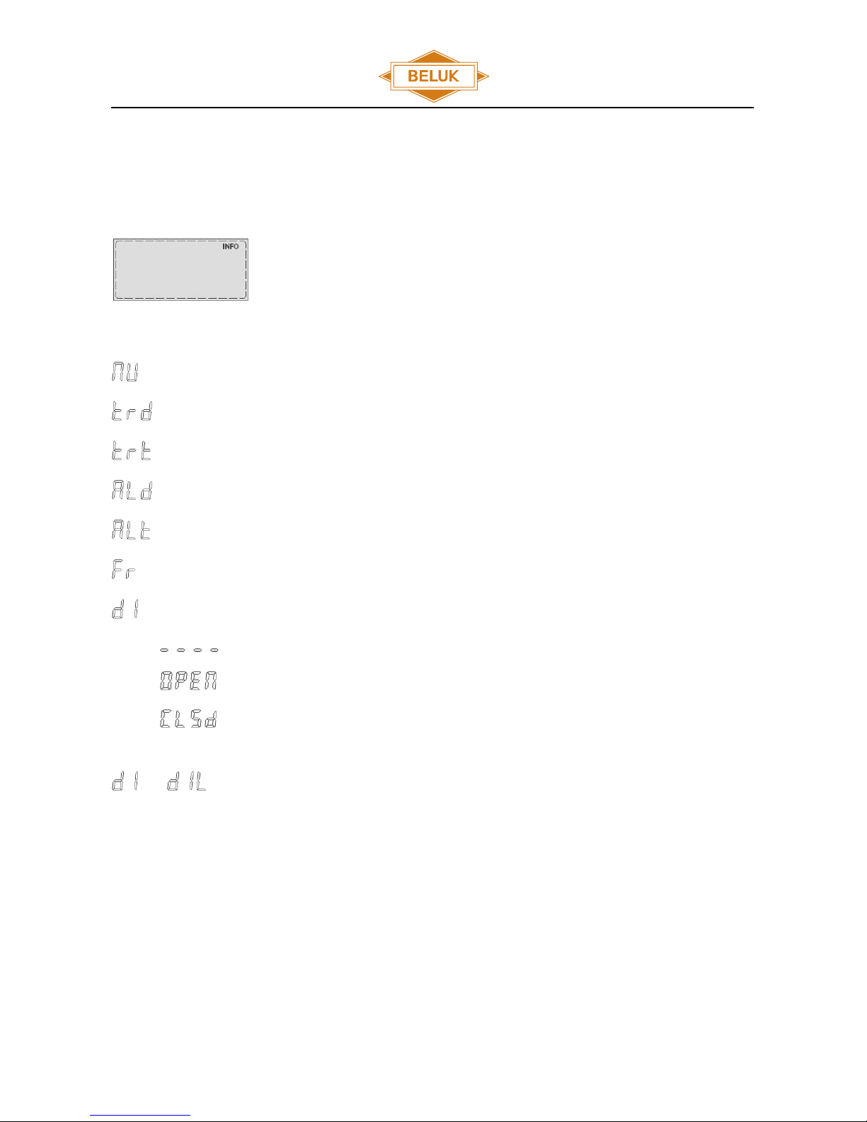
4.1 Info
The main menu "INFO” contains all information’s about the adjusted thresholds, delay times
for trip/alarm and the stored natural unbalance. In the Info menu, it is not possible to change
any values. To enter this menu use the button to select “Info” and enter the menu with
. Submenus can be selected by and .
Displays the stored value of the natural unbalanced current.
Displays the adjusted threshold for trip.
Displays the adjusted time delay for trip
Displays the adjusted threshold for alarm.
Displays the adjusted time delay for alarm.
Displays the software version of the device.
Displays the state of digital input. Possible readings are:
Blocking the monitoring system via DI1 and DI2 is switched off.
Terminals DI1 and DI2 are open.
Terminals DI1 and DI2 are closed.
The monitoring system can be blocked by the digital input. The corresponding settings are explained in the next chapter
and .

Reference Manual
Capacitor Bank Protect. Relay KSR1
Rev. 10
2018-09
11
4.2 Setup
The main menu “Setup” is split into two menu levels:
Level 1 is the “start menu”, it contains settings to commission the KSR1.
Level 2 is the “expert menu”, it contains the complete range of settings. This menu is protected by an additional
password.
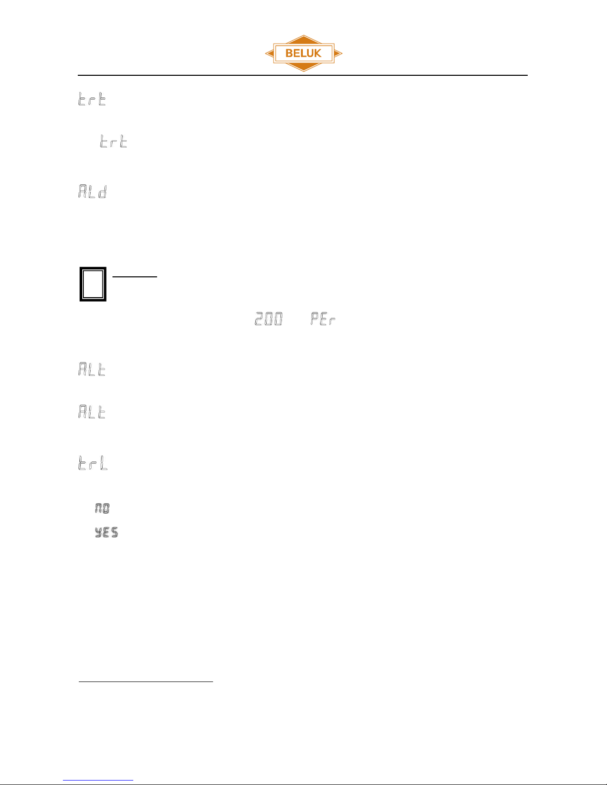
4.2.1 Start menu Password 242
To enter this menu, use the button to select “Setup” and confirm the selection by pushing
. To enter the menu use password (242). The menus can be selected by and , and
entered by .
This menu allows to set the natural unbalance for current or voltage of the monitored
capacitors. To store an entered value push the button . The second line of the display
starts blinking and shows the actual measured value. To store the shown value push the
button again. To set a new value of the natural unbalance push the button again. The stored value of the natural
unbalance is shown in the “Info” menu. The natural unbalance is evaluated as absolute value. Thus, a drop below the
stored value is also shown and evaluated as an increase.
Here, the trip threshold is set. The threshold can be set in a range of 0,2 –20 V for voltage and 20 mA –5 A for current
1
.
It is also possible to set the threshold by a percent value, which refers to the related nominal range of current or voltage.
In factory setting, the absolute value has to be set.
Attention: This value is adapted automatically by subsequent changes of the transformer ratio.
The input can be changed to percent in menu under .
1
When using a VT / CT the set thresholds are multiplied by the adjusted transformer ratio.
!
Reference Manual
Capacitor Bank Protect. Relay KSR1
Rev. 10
2018-09
12
This submenu set the trip delay time. In case, the trip trigger value (voltage or current) is exceeded for a longer period
than , contacts 11-14 will close and 11-12 will open.
Here, the threshold for an alarm can be set. The threshold can be set in a range of 0,2 –20 V for voltage and 20 mA –5
A for current
2
. It is also possible to set the threshold by a percent value, which refers to the related nominal range of
current or voltage. In factory setting, the absolute value has to be set.
Attention: This value is adapted automatically by subsequent changes of the transformer ratio.
The input can be changed to percent in menu under .
Sets the delay time for alarm. In case, the alarm trigger value (voltage or current) is exceeded for a longer period than
, the contacts 21-24 will close and 21-22 will open.
The trip relay output can be configured as either latch able or non-latch able output.
The trip relay goes back to inactive state as soon as the trip value falls below the adjusted threshold.
The trip relay remains in active state even when the trip value falls below the adjusted threshold. To
reset the relay, push the Button for 3 sec. After a brownout, the relay falls back into the state before
the brownout.
2
When using a VT / CT the set thresholds are multiplied by the adjusted transformer ratio.
!

Reference Manual
Capacitor Bank Protect. Relay KSR1
Rev. 10
2018-09
13
The alarm relay output can be configured as either latch able or non-latch able output.
The alarm relay goes back to inactive state as soon as the alarm value falls below the adjusted
threshold.
The alarm relay remains in active state even when the alarm value falls below the adjusted threshold.
To reset push the Button for 3 sec. After a brownout, the relay falls back into the state before the
brownout.
The relay 3 is free to program to become active state with trip, alarm or both. Following settings are possible:
relay 3 is always switched off
relay 3 becomes active with alarm relay
relay 3 becomes active with trip relay
relay 3 becomes active with trip and alarm relay
relay 3 becomes active with trip or alarm relay
The relay 3 output can be configured as either latch able or non-latch able output.
The trip relay 3 goes back to inactive state as soon as the trip / alarm value fall below the adjusted
threshold.
The trip relay 3 remains in active state even when the trip / alarm value falls below the adjusted
threshold. To reset push the Button for 3 sec. After a brownout, the relay falls back into the state
before the brownout.
Reference Manual
Capacitor Bank Protect. Relay KSR1
Rev. 10
2018-09
14
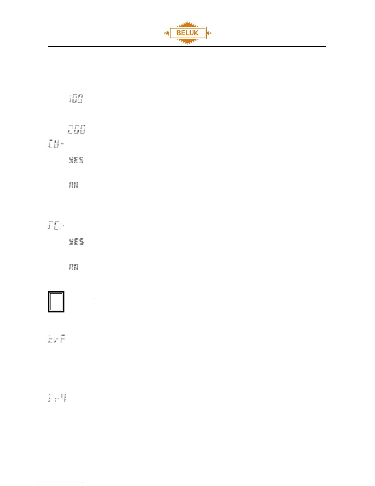
4.2.2 Expert menu Password 511
To enter this menu select “Setup” and enter the expert password (511). Select submenus 100 – 400 by using and .
Enter the submenus by pushing .
4.2.2.1 Start menu
Contains the same settings as start menu above.
4.2.2.2 Measurement menu
Current measuring
The KSR1 measures the current at input K and L. Trip and alarm thresholds are given in A or in
percentage of the nominal input range.
The KSR1 is measuring the voltage at input UM1 and UM2. Trip and alarm thresholds are given in V or
in percentage of the nominal input range.
Values in percent
All values are shown in percentage. The thresholds for voltage or current are set in percentage of the
nominal value of the input.
All values are shown as absolute value. The thresholds for voltage or current are set as absolute value.
Attention: A previous adjusted Transformerratio become set to 1 when altering this item.
Transformer factor
Voltage: adjustable VT ratio from 1-350.
Current: adjustable CT ratio from 1-4000.
Frequency
Here, it is possible to adjust the mains frequency. Possible settings are 50 Hz and 60 Hz. The frequency setting should
be correct otherwise the measurement does not work proper.
!

Reference Manual
Capacitor Bank Protect. Relay KSR1
Rev. 10
2018-09
15
4.2.2.3 Alarm menu
Trip active
When exceeding the adjusted threshold for trip, the trip relays switches and the message
blinks on the display.
An exceeding of the trip threshold is ignored.
Store trip in “Alarm buffer”
Trips are stored with the trigger value in the “Alarm buffer”.
Trips are not stored.
Alarm active
When exceeding the adjusted threshold for trip, the trip relays switches and the message
blinks on the display.
An exceeding of the trip threshold is ignored.
Store alarm in “Alarm buffer”
Alarms are stored with the trigger value in the “Alarm buffer”.
Alarms are not stored.
Drop off ratio (hysteresis)
It is possible to set the hysteresis to 50% –100% of the adjusted thresholds for current and voltage. The “drop off ratio”
defines the threshold, which resets a trip or an alarm when the measured value falls below the adjusted threshold. For
example:
Case 1: Threshold for trip is 0.5 A and “drop of ratio” is 100% => trip is reset when the current falls below 0.5 A.
Case 2: Threshold for trip is 0.5 A and “drop of ratio” is 50% => trip is reset when the current falls below 0.25 A.

Reference Manual
Capacitor Bank Protect. Relay KSR1
Rev. 10
2018-09
16
The KSR1 uses absolute values. For this reason, shown values are always positive independent of their actual
direction (meas. value increases / decreases).
Digital input active
the monitoring system can be blocked via the digital input.
the monitoring system cannot be blocked via the digital input.
Digital input open or closed
monitoring system is blocked when terminals DI1 & DI2 are closed.
monitoring system is blocked when terminals DI1 & DI2 are open.
Attention: The digital input is activated or deactivated by opening or closing the contact DI1 and DI2. Connecting
a voltage signal can destroy the KSR1.
4.2.2.4 Reset menu
reset trip
reset alarm
reset stored alarms and trips
reset natural unbalance
reset the device to factory settings.
change password “setup”. Possible adjustment 000-999. Master password 242.
change password “expert”. Possible adjustment 000-999. Master password 511.
To switch off the password protection, set to 000.
!
!

Reference Manual
Capacitor Bank Protect. Relay KSR1
Rev. 10
2018-09
17
4.3 Alarm
The submenu “Alarm” contains the last 5 trips and the last 5 alarms. The alarms and trips are stored together with the
value, which has triggered the event. The alarm storage is a ring buffer, which means an upcoming trip/alarm deletes
the oldest event if the buffer is full. It is also possible to clear all trips or alarm in menu 400 “Reset menu”.
To select the “Alarm” menu, the button is used. In order to enter the menu has to be
pushed. Select the events by pushing the buttons and .

Reference Manual
Capacitor Bank Protect. Relay KSR1
Rev. 10
2018-09
18
5 Technical Data KSR1
Auxiliary voltage
40 –250 V AC, 45 –65 HZ / 40 –300 V DC, 5 VA; max. fuse 6 A
Voltage measuring
0,1 –20 V; burden 284 kOhm; vt-ratio from 1 –350, with low pass filter
Continuous overload: 120 V
Short term overload: 500 V for ten seconds
Accuracy: 0.5 % from upper range value
Current measuring
15 mA –5 A; burden 20 mOhm; ct-ratio from 1-4000, with low pass filter
Continuous overload: 25 A
Short term overload: 100 A for one second
Accuracy: 0.5 % from upper range value
Relay outputs
4 output relays, change over contact, potential-free, max fuse 6 A
Function:
Relay 1: Trip
Relay 2: Alarm
Relay 3: Adjustable: Alarm, trip or both
Relay 4: Status
Max. output rating AC: 1250 VA, max switching voltage: 440 V AC
Max. output rating DC (ohmic): 30 V / 5 A; 60 V / 1 A; 110 V / 0,5 A; 220 V / 0,3 A
Digital input
Blocking Alarm / Trip via digital input.
Interface
TTL, rear (optional accessories TTL-USB converter)
Ambient temperature
Operation: -20 °C –70 °C, storage: -40 °C –85 °C
Humidity
0 % - 95 %, without moisture condensation
Overvoltage class
II, pollution degree 3 (DIN VDE 0110, Teil 1 / IEC 60664-1)
Standards
DIN VDE 0110 part 1 (IEC 60664-1:1992)
VDE 0411 part 1 (DIN EN 61010-1 / IEC 61010-1:2001)
VDE 0843 part 20
(DIN EN 61326 / IEC 61326: 1997 + A1:1998 +A2: 2000)
Conformity and listing
CE
Terminals
screw-type, max. 2,5 mm2
Casing
front: instrument casing plastic (UL94-VO), rear: metal
Protection class
Front: IP50, (IP54 by using a gasket), Rear: IP20
Weight
ca. 0,65 kg
Dimensions
144 x 144 x 58 mm (h x w x d), cutout 138+0,5 x 138+0,5 mm

Reference Manual
Capacitor Bank Protect. Relay KSR1
Rev. 10
2018-09
19
6 Menu overview
MEAS U / I
INFO
SETUP
ALARM
In % / V / A
242
100
Natural unbalance U / I („NU“)
511
100
Natural unbalance U / I („NU“)
Trip value "trd"
Trip value "trd"
Trip time "trt"
Trip time "trt"
"tr1"
Alarm value "Ald"
Alarm value "Ald"
"tr2"
Alarm time "Alt"
Alarm time "Alt"
"tr3"
Software version "Fr"
Trip latchable "trL"
"tr4"
Di state "dl"
Alarm latchable "ALL“
"tr5"
Relay 3 "r3"
"AL1"
Relay 3 latchable "r3L"
"AL2"
"AL3"
200
Current / voltage metering "Cur“
"AL4"
Display absolute value or % "Per"
"AL5"
Transformer factor "trF"
Line frequency "Frq"
300
Trip active "tr"
Store trip in buffer "trs"
Alarm active "AL"
Store alarm in buffer "ALS"
Drop off ratio "dor"
Activate DI "dl"
DI open or closed "dIL"
400
Reset trip "rtr"
Reset alarm "rAL"
Reset stored alarms "rSE"
Reset natural unbalance "rNU"
Reset to factory settings "rFS"
Password setup "PS"
Password expertmenu "PE"

Reference Manual
Capacitor Bank Protect. Relay KSR1
Rev. 10
2018-09
20
7 Dimensions
Table of contents
Other Beluk Other manuals


Popular Other manuals by other brands


KSB
KSB Hya-Duo D FL Compact Installation & operating manual

Honeywell
Honeywell GasAlertQuattro Operator's manual

Horse Power Ignition
Horse Power Ignition HPI 210 installation manual

COBHAM
COBHAM ERU50-001 Installation and operation manual

Lenovo
Lenovo S90-A quick start guide

inveo
inveo RFID IND-U2 user manual