Beluk KSR User manual

Reference Manual
Capacitor Bank Protection-Relay KSR
Rev. 13
2018-07
Beluk GmbH
Taubenstrasse 1
86956 Schongau
Germany
Tel.: +49/(0)8861/2332-0
Fax: +49/(0)8861/2332-22
E-Mail: [email protected]
Web: http://www.beluk.de
Reference Manual
Capacitor-Bank Protection-Relay
KSR

Reference Manual
Capacitor Bank Protection-Relay KSR
Rev. 13
2018-07
2
Revision history
Date
Name
Revision
Change
26.05.04
CE
01
initial document release
15.12.04
CE
02
new firmware (V1.05)
21.03.05
ATh
03
new firmware (V1.06)
11.04.06
ATh
04
new firmware (V1.8.1)
14.03.07
ATh
05
general additions
04.04.07
ATh
06
new firmware (V1.12.x)
09.10.08
Le
07
new firmware (V1.14.x)
17.06.09
Le
08
add fault recorder
28.05.10
Le
09
new firmware (V1.16.x)
27.08.10
27.09.11
09.12.15
Le
MR
RH
10
11
12
add option –E
new Document
correct Password
17.07.18
SO
13
correct contents

Reference Manual
Capacitor Bank Protection-Relay KSR
Rev. 13
2018-07
3
Contents
1. Overview ................................................................................................................................................................ 5
2. Protection Function and Other Features ................................................................................................................. 6
2.1 Introduction.......................................................................................................................................................... 6
2.2 Protection Elements ............................................................................................................................................. 7
2.2.1 Overload and Unbalance protection...................................................................................................................... 7
2.2.2 Overvoltage and Undervoltage Protection ............................................................................................................ 7
2.2.3 Hysteresis of threshold values ............................................................................................................................... 7
2.2.4 Output contacts ..................................................................................................................................................... 8
2.3 Other features ...................................................................................................................................................... 9
2.3.1 Natural unbalance compensation.......................................................................................................................... 9
2.3.2 Metering functions ................................................................................................................................................ 9
2.3.3 Alarm system ......................................................................................................................................................... 9
2.3.4 Digital Input ......................................................................................................................................................... 10
2.3.5 Fault recorder ...................................................................................................................................................... 10
2.3.6 Usage ................................................................................................................................................................... 12
3. Technical Specifications .........................................................................................................................................24
3.1 General ................................................................................................................................................................24
3.2 Current and Voltage Input ...................................................................................................................................24
3.3 Auxiliary Supply ...................................................................................................................................................24
3.4 Temperature Measuring ......................................................................................................................................24
3.5 Settings................................................................................................................................................................25
3.6 Output Contacts...................................................................................................................................................25
3.7 Connections .........................................................................................................................................................25
3.8 Interface ..............................................................................................................................................................26
3.9 Environmental Withstand ....................................................................................................................................26
3.10 Standards...........................................................................................................................................................26
4. Drawings................................................................................................................................................................27
4.1 Connection diagram.............................................................................................................................................27
4.2 Dimensions ..........................................................................................................................................................28
4.3 Diagram ...............................................................................................................................................................29
5. Applications...........................................................................................................................................................30

Reference Manual
Capacitor Bank Protection-Relay KSR
Rev. 13
2018-07
4
6. Commissioning Guide ............................................................................................................................................31
6.1 Test......................................................................................................................................................................31
6.2 Installation...........................................................................................................................................................31
6.3 Connection ..........................................................................................................................................................31
6.4 Preparation..........................................................................................................................................................32
7. Maintenance .........................................................................................................................................................33
8. Appendix ...............................................................................................................................................................34

Reference Manual
Capacitor Bank Protection-Relay KSR
Rev. 13
2018-07
5
1. Overview
KSR Capacitor Bank protection device has been designed to protect the capacitors from overload, over
voltage and unbalance with the advanced and flexible microprocessor technology.
A wide range of protection elements are supplemented by advanced features such as control, metering, data
storage, fault recorder, remote communications, supervision and self-monitoring features.
An LCD display on the front of the device gives user-friendly access to read the measurements, view and edit
relay settings and operational annunciations. The backlit provides a good visibility even in the poor room
illumination. Four context soft keys facilitate easy and flexible parameterization through LCD display without
the need of manual.
An interface is provided at the rear side of the device for remote communications via RS485 with MODBUS
protocol.

Reference Manual
Capacitor Bank Protection-Relay KSR
Rev. 13
2018-07
6
2. Protection Function and Other Features
2.1 Introduction
KSR device accepts 4 current inputs and 3 voltage inputs.
A full range “Fast Fourier Transformation” is performed on the input data of all channels (3 Voltage channels,
4 Current channels). Thus provides information about the harmonic contents which distort the sine waveform
of the current and voltage channels.
Current inputs are available with two options either 1A input or 5A input.
Current IL1IL2IL3 inputs used to achieve overload protection, while IUB achieves unbalance protection. Current
measurements are derived from these inputs.
Voltage VL1VL2VL3 inputs used to achieve over voltage and under voltage protection. Voltage measurements
are derived from these inputs.

Reference Manual
Capacitor Bank Protection-Relay KSR
Rev. 13
2018-07
7
2.2 Protection Elements
2.2.1 Overload and Unbalance protection
Current IL1IL2IL3 and IUB elements provide Overload and Unbalance protection respectively. Each element can
be programmed to have two independent stages for current setting and DTL (definite time lag) characteristic
as described in section 3.
Samples of the current input signals are taken at a frequency of 12.8 kHz. This enables KSR to act as a True
RMS measuring device (TRMS) over a wide frequency range.
The KSR relay comes with an automatic damping function of the current inputs inputs. This
damping function is used to avoid accidental deployments.
The damping function works as an exponential curve. For every new measurement it took 10%
of the former measurement. Depending on the ratio between signal level on the input and adjusted
threshold, it can result some delay before starting the real delay time.
The real delay time is only starting when the adjusted threshold is exceeded.
2.2.2 Overvoltage and Undervoltage Protection
Voltage VL1VL2VL3 elements provide Over-voltage and Under-voltage. Each element can be programmed to
have two independent stages for current setting and DTL (definite time lag) characteristic as described in
section 3.
Samples of the voltage input signals are taken at a frequency of 12.8 kHz. This enables KSR to act as a True
RMS measuring device (TRMS) over a wide frequency range.
2.2.3 Hysteresis of threshold values
For the adjusted alarm thresholds, the KSR uses depending on the trigger a pickup respectively a dropout
ratio. In case of monitoring a value "greater than", the device triggers an alarm at the adjusted value and go
back to normal at value * 0,97. For the monitoring of values "less than", the function works vice versa (value
* 1,03).
!

Reference Manual
Capacitor Bank Protection-Relay KSR
Rev. 13
2018-07
8
2.2.4 Output contacts
KSR relays are available with two types of output contacts
-two change over contacts
-four normally open contacts
Output contacts are user programmable to operate from protection characteristic, DTL for different
protection functions and relay self-monitoring feature (watchdog). These output contacts are shown in de-
energized state in the drawing under section 4.
Under normal mode of operation, output contacts remain energized for at least 100ms or for the duration of
fault detected by the protection function. Alternatively, outputs can be programmed to operate as latching
contacts, if required. It is also possible to invert the operation of the output contacts.

Reference Manual
Capacitor Bank Protection-Relay KSR
Rev. 13
2018-07
9
2.3 Further features
2.3.1 Natural unbalance compensation
The KSR contains the function "natural unbalance compensation". This function allows to measure and store
the natural unbalance current (Inuc)at the protected capacitor banks. The value of the natural unbalance
current depends on production tolerances. During the normal operation the KSR subtracts the stored Inuc
value from the current In. The result of this operation should be "0". In case of variations of this result it is
possible to set a limit between 0.01A and 50kA to trigger an alarm.
2.3.2 Metering functions
The KSR metering features provide continuous measurement of Currents and Voltages which are connected
as analogue inputs. The signal processor calculates different values from these inputs.
VLine to Neutral TRMS Voltages VL1-N, VL2-N, VL3-N
VLine to Line TRMS Voltages VL1-L2, VL2-L3, VL3-L1
I TRMS Current IL1, IL2, IL3, IUB
If RMS values of fundamental waves of currents (without harmonics)
Harmonics Order of (2-63) for current and voltages
THD THD –factors for voltages (VLine to Neutral) and all 4 currents
Ith exponentially damped current values to simulate thermal measurement
1
T ambient temperature
2.3.3 Alarm system
The KSR allows the programming of the output relays to produce alarms or trips. The alarm or trip system
works with two separate facilities:
The output relays can be programmed separately. Each relay implements an inversion feature as well as
a hold state in which the user must manually reset the relay after activating alarm or trip has become
1
Please check Appendix A for detailed explaination of thermal damping function.

Reference Manual
Capacitor Bank Protection-Relay KSR
Rev. 13
2018-07
10
inactive again. The relays receive signals to “activate themselves” from one or more of the 32
configurable alarms. Depending on its inversion setting, the relay closes or opens on activation.
A maximum of 32 alarms or trips can be assigned. Each of them continuously compares a value to an
assigned limit. If a selectable alarm or trip condition is true (value>limit or value<limit), a delay timer is
started. After the selected delay time is over, the alarm or trip sends the activation signals to all output
relays, which are programmed as “targets” for this alarm or trip. A second, configurable timeout delay
can be set for the time between the reset of the alarm condition and the transmission of the deactivation
signals to the output relays. Additional to the adjustable delay times, the KSR contains an separate
dropout respectively pickup ratio to avoid a hunting of the alarm condition. This function works
depending on the adjusted trigger. For a trigger "greater than" the alarm condition is not is true at the
adjusted limit and untrue at adjusted limit * 0.97. For trigger "less than" the function works vice versa. A
graphical display message can be used to show the alarms in the LCD of the device. This message can be
programmed either with manually or automatically reset. The alarm display message is treated as if it
was another output relay (so it can simply be selected as target for an alarm). Also it is possible to store
for each alarm event date and time for activating and deactivating the alarm.
The high flexibility of this alarm system is achieved due to the following points:
1. One alarm or trip can cause the activation of one or more output relays.
2. One relay can be activated from more than one alarm or trip. If two or more alarms use the same relay
as output, a logical OR condition is used: one active alarm or trip suffices to cause the relay to switch.
Both, relays and alarms, are invertible in their function.
2.3.4 Digital Input
Each trip or alarm can be blocked via the DI. This input is detected as active, when there is a voltage between
50 - 132 V DC. See details at chapter 2.3.5.8.
2.3.5 Fault recorder
If the KSR is equipped with the integrated fault recorder, it is possible to store each triggered Alarm event.
The integrated fault recorder of the KSR provides 64 memory cells. Each of them stores one Event (ON/OFF).
Each event is stored with the following information:

Reference Manual
Capacitor Bank Protection-Relay KSR
Rev. 13
2018-07
11
Seite 1:________________________________________________________________________________
RECORD: Indicates in, which place of the memory the alarm is stored.
ALARM XX: Shows which alarm was triggered ON: Alarm active
OFF: Alarm inactive
DATE: Date of the alarm event.
TIME: Time of the alarm event.
Date and time can be set under „setup parameter“.
LIMIT: Which limit was exceeded.
EXT-VAL: Shows the maximum limit exceedance in the moment of the alarm event.
Button „“ is used to visit the next page.
Seite 2:________________________________________________________________________________
RECORD: Indicates in which part of the memory the alarm is stored.
ALARM XX: Shows which alarm was triggered ON: Alarm active
OFF: Alarm inactive
Value in the moment of the alarm event
U (in Volt) I(in Ampere)
L12 0.00 1 0.0
L23 0.00 2 0.0
L31 0.00 3 0.0
UB 0.0
Button „“ is used to visit the next page.
Seite 3:________________________________________________________________________________
RECORD: Indicates in which part of the memory the alarm is stored.
ALARM XX: Shows which alarm was triggered ON: Alarm active
OFF: Alarm inactive
DELAY: Time Delay from exceeding the adjusted level to activate an alarm.
RELAY: What happens in case of an alarm (display alarm / activate relay / etc.).

Reference Manual
Capacitor Bank Protection-Relay KSR
Rev. 13
2018-07
12
2.3.6 Usage
The device provides 4 keys to the user to accept any inputs. The keys are numbered key 1... key 4 from left
to right. The actual function of a certain key changes due to the actual context. The keys function is indicated
by small pictograms in the bottom line of the display.
After turning on the supply power, the KSR automatically starts with displaying values of the measurement
menu. The key, which is labelled with capital letters „M“ can be used to switch to the main menu.
2.3.6.1 Main menu
In the main menu, one can choose between the following possibilities:
measurement = display measured values
harmonics = display harmonics
setup = device setup sub-menu
device info = display device information
reset alarms = reset all relays, configured with “manual reset”
fault recorder = displays all recorded alarms with time stamp and grid data's
Use the keys „“ and „“ to place the desired entry next to the tiny arrow („>“) on the left side. Press the
„“ - key to activate the selected entry.
Whenever a capital “M” is used as key symbol in any sub-menu, pressing the key will switch
straight to the main menu.
!
Reference Manual
Capacitor Bank Protection-Relay KSR
Rev. 13
2018-07
13
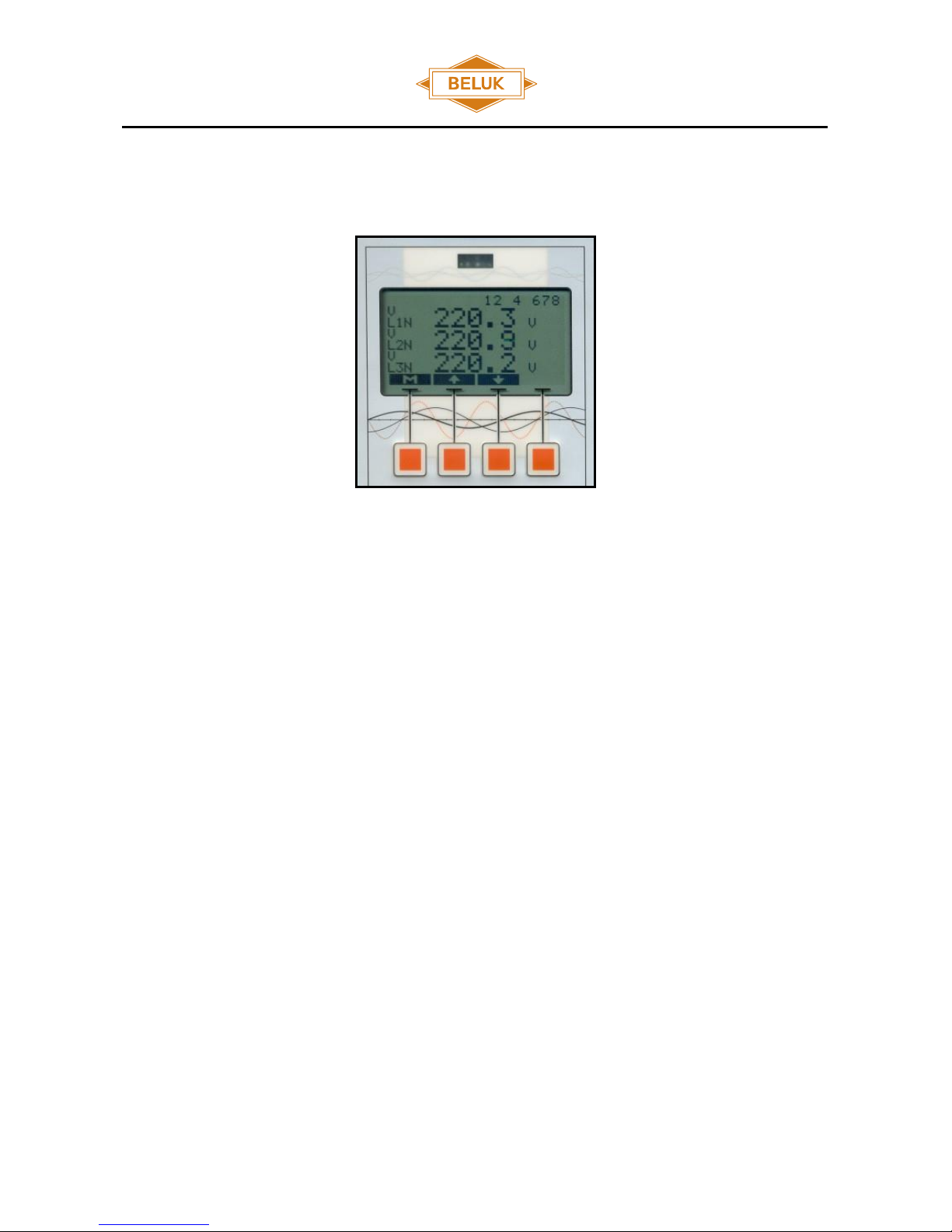
2.3.6.2 Menu “measurement”
This menu holds nearly all the measured values. Each value is displayed together with its name (VLN, Ith,... )
and its origin (L1, L2, L3, N). The units of the measured values are also displayed. Use keys „“ and „“ to
select from the variety of measured values.
In the top line the actual state of the assembled relays is shown with the backlit on each number. A dark
number on bright ground represents an inactive relay. Inverse display (bright number on dark ground)
indicates an activated relay.
The „M“ - key switches back to the main menu.
Reference Manual
Capacitor Bank Protection-Relay KSR
Rev. 13
2018-07
14
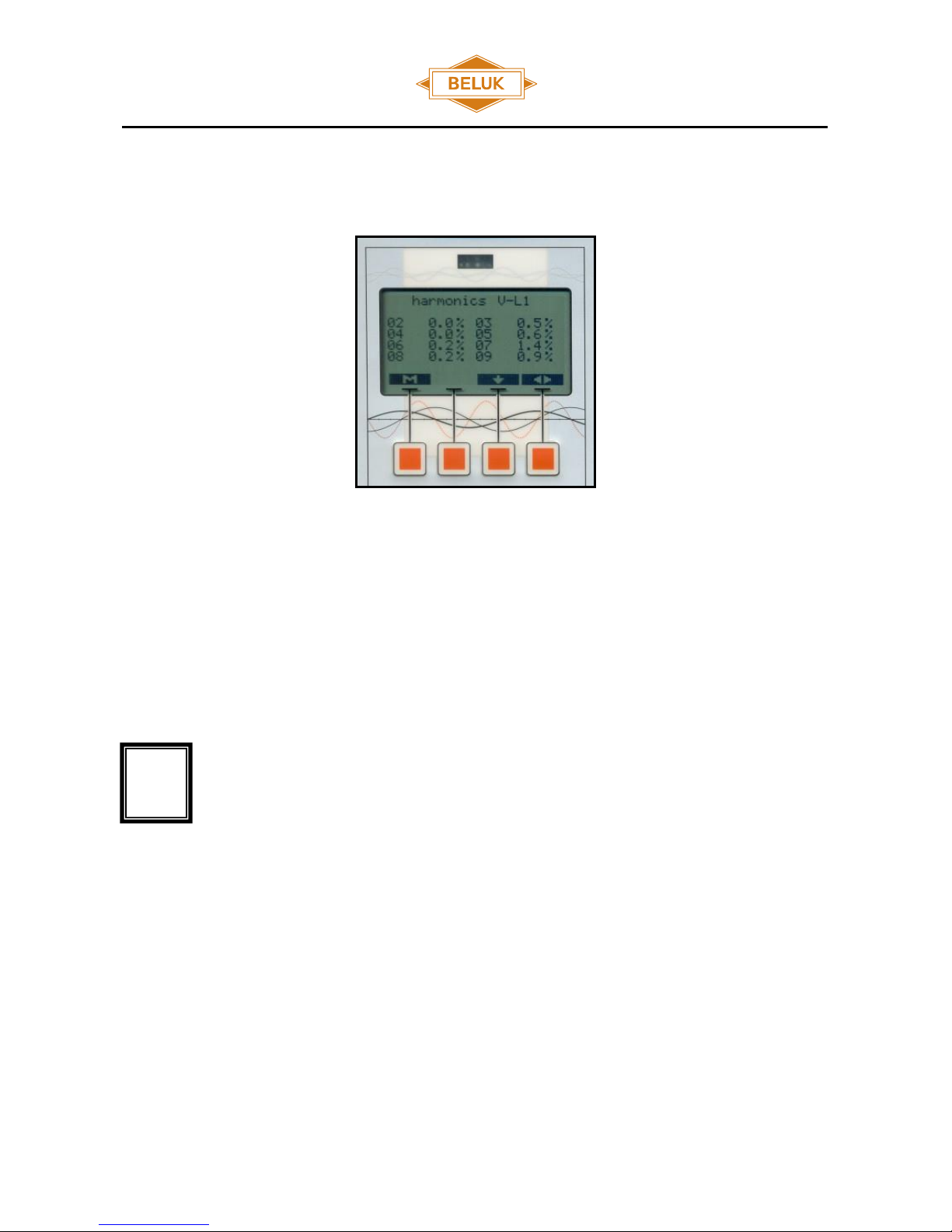
2.3.6.3 Menu “harmonics”
All harmonics are normalized to 100% of the fundamental harmonic. Key ““ selects the data source
(voltages, currents), ““ and ““ move the display to higher and lower harmonics. The index, which is shown
with each harmonic, specifies its order. The fundamental harmonic (index 01) is not shown as it is always
100%.
If the harmonic display quotes “not available”, the current or voltage, which sources the
harmonic calculation is below a certain limit or even not present. This makes the FFT
calculation of the harmonics very inaccurate or impossible.
!

Reference Manual
Capacitor Bank Protection-Relay KSR
Rev. 13
2018-07
15
2.3.6.4 Menu “setup”
The „setup“-menu is protected from unauthorized usage by means of a password. The password is fixed
(„2402“). Because of the huge amount of setup possibilities, a set of submenus is used.
At certain points the user will be confronted with the need to enter numeric values. The KSR will prompt with
the old or a default value. One digit of this value will be marked with a “-“ below it. Now this digit can be
changed with the „+“ and „-“ keys. „“ will switch to the next digit which can then be altered as described.
After you have reached the last digit, press the right button once more and the new value will be used by the
device.
Reference Manual
Capacitor Bank Protection-Relay KSR
Rev. 13
2018-07
16
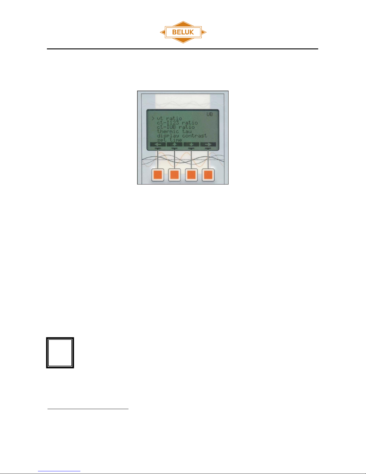
2.3.6.5 Menu “setup->parameter”
System parameters:
„vt ratio“ - ratio of a VT
„ct-I123 ratio“ - ratio of CT for L1, L2 L3
„ct-Iub ratio“ - ratio of a CT for current 4 (unbalance current)
„thermic tau“ - time constant for calculation of Ith
2
„display contrast“ - display contrast setting
"set time" –time and date for the integrated data storage
„set UB comp.“ – measure and store the value for the natural unbalance
„clear UB comp.“ – clear the stored value for the natural unbalance (Appears only when UB current is
set)
Top right you can see if the UB current is set or not. If the UB current is set, the UB sign is
marked in black.
2
Please check Appendix A for detailed explaination of thermal damping function.
!
Reference Manual
Capacitor Bank Protection-Relay KSR
Rev. 13
2018-07
17
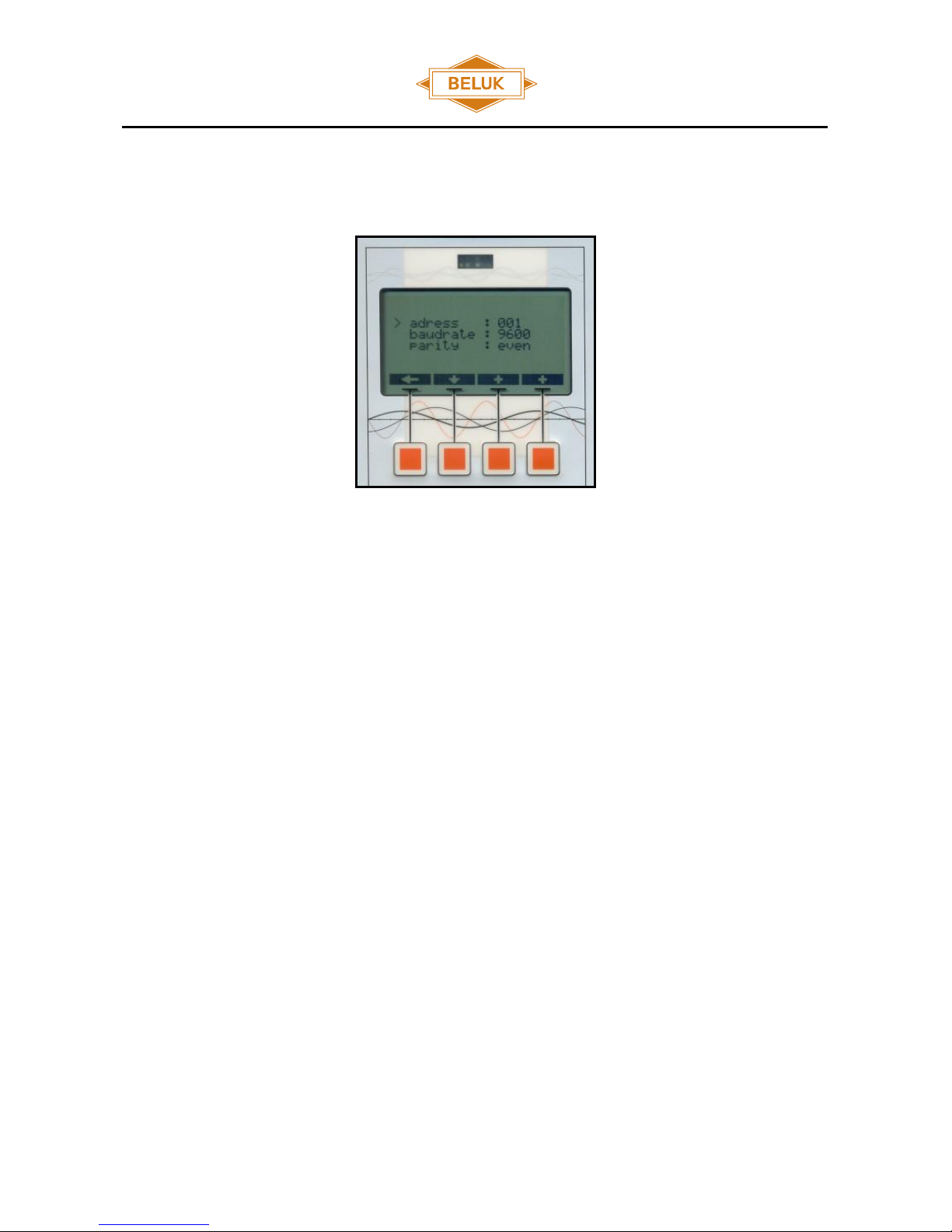
2.3.6.6 Menu “setup->modbus”
This menu contains all MODBUS settings:
address - modbus slave address of the device
baudrate - data transfer speed over serial RS485 connection
parity - parity setting for serial connection
For details consult the separate technical documentation for KSR Modbus.
Reference Manual
Capacitor Bank Protection-Relay KSR
Rev. 13
2018-07
18
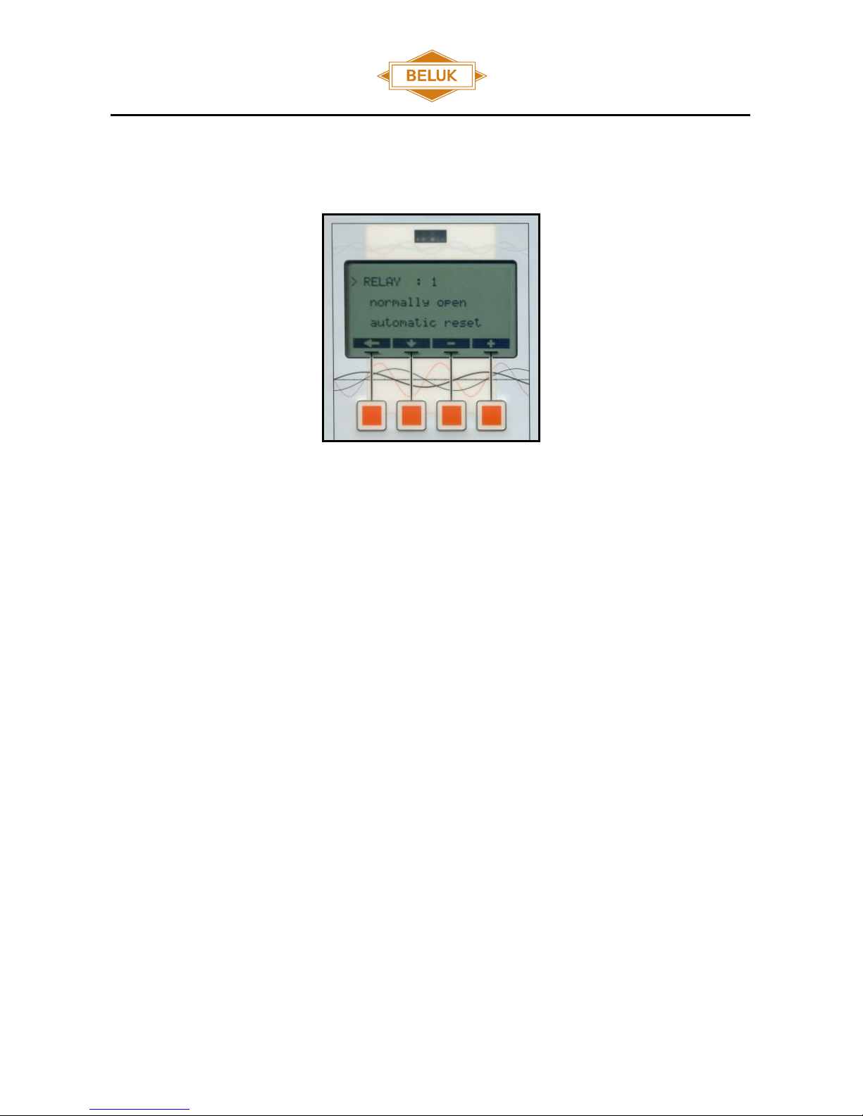
2.3.6.7 Menu “setup->relay”
Setup for the relays:
„normally open normally closed“ - this selects the relay inversion. If one chooses „normally open“,
the relay will be open in inactive state and it will close on activation. “normally closed” inverts this
behaviour.
„automatic reset manual reset“ - If a relay is set to “manual reset”, it will stay activated once it has
been triggered by an alarm or trip, even if the alarm or trip is inactive again (hold state). If “automatic
reset” is used, the relay will fall back to inactive state automatically once the activating alarms or trips
have become inactive again.
Reference Manual
Capacitor Bank Protection-Relay KSR
Rev. 13
2018-07
19
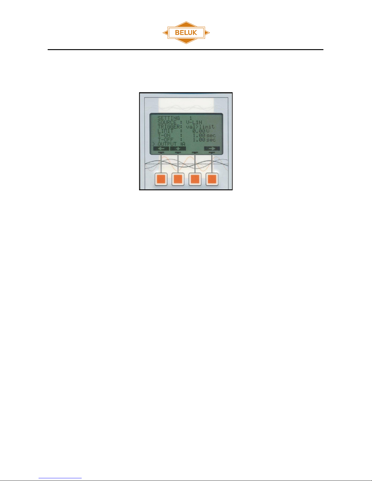
2.3.6.8 Menu “setup->protection settings”
SOURCE : this selects the data source
TRIGGER : trigger condition
LIMIT : selection of the limit value
T-ON : turn-on delay time ( 0 –600s )
T-OFF : turn-off delay time ( 0 –600s )
OUTPUT : selection of the relays, which shall be activated if alarm condition is true and after T-ON is over.
The alarm display feature can be selected here too, as if it was another relay output. For each display
alarm a display message can be adjusted, it is possible to select the following messages: UB alarm or trip,
OV alarm or trip, UV alarm or trip, OL alarm or trip. The setting for automatic or manual reset works the
same as with output relays. Also it can be adjusted if a alarm is stored in the fault recorder and if the
alarm is disabled when the DI is active.

Reference Manual
Capacitor Bank Protection-Relay KSR
Rev. 13
2018-07
20
2.3.6.9 Menu “setup ->set password”
This submenu allows to change password from factory setting (2402) to customer requirement.
2.3.6.10 Menu "setup -> clear faultrecorder"
This function allows to delete the content of the storage cells from the fault recorder.
Other manuals for KSR
1
Table of contents
Other Beluk Other manuals


Popular Other manuals by other brands


Bosch
Bosch ACS 561 Repair instructions

Fluval
Fluval Roma instruction manual

Roger Technology
Roger Technology BIONIK Instruction and warnings for the installer

ASCOM
ASCOM VOWIFI SYSTEM - brochure

Unical
Unical Unisun Slim Installation and Servi?ing Manual

HURST
HURST Mastershift 3-Speed Installation Kit installation instructions

CertainTeed
CertainTeed STRUCTURAL PORCH POST Step-By-Step Instructions

Boulevard
Boulevard DVLL41FP92(N Installation instructions and owner's manual

BRADEN
BRADEN PD12C Series MATERIAL LIST AND INSTALLATION INSTRUCTIONS

Aion Electronics
Aion Electronics ANTIPODE manual

Opticon
Opticon OPL-9815 quick start guide

Paradyne
Paradyne ACCULINK 3161 quick reference