Boulevard DVLL41FP92(N Quick start guide

LUXURY DIRECT VENT ZERO CLEARANCE
GAS FIREPLACE HEATER
CONTEMPORARY
DVLL41FP92(N,P)-3
TRADITIONAL
DVTL41BP90(N,P)-1
UL FILE NO. MH30033
INSTALLATION INSTRUCTIONS
AND
OWNER’S MANUAL
WARNING: If not installed, operated and maintained
in accordance with the manufacturer’s instructions,
this product could expose you to substances in fuel
or from fuel combustion which can cause death or
serious illness.
This appliance may be installed in
an aftermarket, permanently located,
manufactured home (USA only) or mobile
home, where not prohibited by state or local
codes.
This appliance is only for use with the type
of gas indicated on the rating plate. This
appliance is not convertible for use with other
gases, unless a certied kit is used.
WARNING
FIRE OR EXPLOSION HAZARD
Failure to follow safety warnings exactly
could result in serious injury, death or
property damage.
— Do not store or use gasoline or other am-
mable vapors and liquids in the vicinity of
this or any other appliance.
— WHAT TO DO IF YOU SMELL GAS
• Do not try to light any appliance.
• Do not touch any electrical switch; do
not use any phone in your building.
• Leave the building immediately.
• Immediately call your gas supplier
from a neighbor’s phone. Follow the
gas supplier’s instructions.
• If you cannot reach your gas supplier,
call the re department.
— Installation and service must be per-
formed by a qualied installer, service
agency or the gas supplier.
INSTALLER: Leave this manual with the appliance.
CONSUMER: Retain this manual for future reference.
�
GAS-FIRED
Page 1

33598-6-0115Page 2
TABLE OF CONTENTS
IMPORTANT SAFETY INFORMATION ......................................................................................... 3
SAFETY INFORMATION FOR USERS OF LP GAS ..................................................................... 4
REQUIREMENTS FOR MASSACHUSETTS ................................................................................ 5
INTRODUCTION ........................................................................................................................... 6
SPECIFICATIONS ......................................................................................................................... 7
FIREPLACE DIMENSIONS ........................................................................................................... 7
CLEARANCES .............................................................................................................................. 8
LOCATING FIREPLACE................................................................................................................ 9
GAS SUPPLY .............................................................................................................................. 10
SPECIAL VENT SYSTEMS ......................................................................................................... 11
INSTALLATION....................................................................................................................... 11-13
VENTING FIREPLACE...........................................................................................................14-19
EXAMPLES - TOP VENT RUN...............................................................................................20-21
TERMINATION CLEARANCES................................................................................................... 22
VENT CLEARANCES.................................................................................................................. 23
VENT SYSTEM IDENTIFICATION .............................................................................................. 24
VENTING FRAMING AND FINISHING...................................................................................25-26
HORIZONTAL TERMINATION..................................................................................................... 27
VERTICAL TERMINATION .....................................................................................................28-29
DVVK-4F FLEX VENT INSTRUCTIONS ..................................................................................... 30
FINISHING THE WALL...........................................................................................................31-32
DVTL LOG & EMBER PLACEMENT ........................................................................................... 33
DVLL DECORATIVE MEDIA INSTALLATION.............................................................................. 34
LIGHTING INSTRUCTIONS........................................................................................................ 35
OPERATING INSTRUCTIONS...............................................................................................36-37
MAINTENANCE INSTRUCTIONS..........................................................................................37-38
WIRING DIAGRAM...................................................................................................................... 38
MAINTENANCE AND SERVICE ................................................................................................. 39
ACCESSORIES........................................................................................................................... 40
OPTIONAL PORCELAIN PANELS (DVTL ONLY) ....................................................................... 40
OPTIONAL DECORATIVE GLASS PANELS (DVLL ONLY)........................................................ 41
DVLL PARTS LIST....................................................................................................................... 42
DVLL EXPLODED VIEW ............................................................................................................. 43
DVTL PARTS LIST....................................................................................................................... 44
DVTL EXPLODED VIEW ............................................................................................................. 45
MASTER PARTS DISTRIBUTOR LIST ....................................................................................... 46
HOW TO ORDER REPAIR PARTS ............................................................................................. 46
JUNCTION BOX WIRING INSTALLATION INSTRUCTIONS...................................................... 47
ACCENT LAMP LIGHT REPLACEMENT - DVLL........................................................................ 47
QUICK REFERENCE GUIDE.................................................................................................48-49
WARRANTY ................................................................................................................................ 50
APPLIANCE SERVICE HISTORY ............................................................................................... 51
SECTION PAGE

33598-6-0115 Page 3
DO NOT OPERATE THIS APPLIANCE WITHOUT GLASS FRONT PANEL INSTALLED
Before enclosing the vent pipe assembly, operate the appliance to ensure it is venting properly.
• If this appliance is installed directly on carpeting,
tile or other combustible material other than wood
ooring the appliance shall be installed on a metal
or wood panel extending the full width and depth of
the appliance.
The base referred to above does not mean the
reproof base as used on wood stoves. The protection
is for rugs that are extremely thick and light colored
tile.
• Children and adults should be alerted to the hazards
of high surface temperatures and should stay away
to avoid burns or clothing ignition.
• Young children should be carefully supervised when
they are in the same room as the appliance.
• Clothing or other ammable material should not be
placed on or near the appliance.
• Adequate accessibility clearances for servicing and
proper operation.
• This appliance must not share or be connected to a
ue serving a separate solid-fuel burning appliance.
• Keep the area around your appliance clear of
combustible materials, gasoline and other ammable
vapor and liquids.
• Under no circumstances should any solid fuels
(wood, coal, paper or cardboard etc.) be used in this
appliance.
• The ow of combustion and ventilation air must not
be obstructed in any way.
• Young children should be carefully supervised
when they are in the same room as the appliance.
Toddlers, young children, and others may be sus-
ceptible to accidental contact burns. A physical
barrier is recommended if there are at-risk individ-
uals in the house. To restrict access to a replace
or stove, install an adjustable safety gate to keep
toddlers young children, and other at-risk indiv-
icuals out of the room and away from hot surfaces.
• A barrier designed to reduce the risk of burns from
the hot viewing glass is provided with this appli-
ance and shall be installed for the protection of
children and other at-risk individuals.
• If the barrier becomes damaged, the barrier shall
be replaced with the manufacturer’s barrier for
this appliance.
• Any safety screen, guard, or barrier removed for
servicing an appliance must be replaced prior to
operating the appliance.
• Due to high temperatures the appliance should be
located out of trafc and away from furniture and
draperies.
• Theglassfrontoranypartremovedforservicingthe
appliance must be replaced prior to operating the
appliance.Workshouldbedonebyaqualiedservice
person.
• Keepburnerandcontrolcompartmentclean.
• Ventcapishotwhilereplaceisinoperation.
• Installationandrepairshouldbedonebyaqualied
service person. The appliance should be inspected
beforeuseandatleastannuallybyaqualiedservice
person.Morefrequentcleaningmayberequireddue
toexcessivelintfromcarpeting,beddingmaterials,etc.
Itisimperativethatcontrolcompartments,burnersand
circulatingairpassagewaysoftheappliancebekept
clean.
• Donotputanythingaroundthereplacethatwillobstruct
theowofventilationair.
• Clearanceinaccordancewithlocalinstallationcodes
andtherequirementsofthegassupplier.
• Do keep the appliance area clear and free from
combustible material, gasoline and other ammable
vaporsandliquids.
• Doexamineventingsystemperiodicallyandreplace
damagedparts.
• Domakeaperiodicvisualcheckofpilotandburners.
Cleanandreplacedamagedparts.
• CAUTION:Theglassusedinyourreplaceisceramic
glass.Iftheglassiscrackedordamagedinanyway,it
shouldbereplacedonlywithacompleteglassframe
assemblyfromEmpire.See parts list on Pages 42
to 45.
• Donotusethisreplaceifanyparthasbeenunder
water.Immediatelycallaqualiedservicetechnician
to inspect the heater and to replace any part of the
controlsystemand anygascontrolwhichhas been
underwater.
• Any safety screen or guard removed for servicing
anappliancemustbereplacedpriortooperatingthe
appliance.
IMPORTANT SAFETY INFORMATION

33598-6-0115Page 4
Some people cannot smell well. Some people cannot smell the
odor of the chemical put into the gas. You must nd out if you
can smell the odorant in propane.Smokingcandecreaseyour
abilitytosmell.Beingaroundanodorforatimecanaffectyour
sensitivityorabilitytodetectthatodor.Sometimesotherodorsin
theareamaskthegasodor.Peoplemaynotsmellthegasodor
ortheirmindsareonsomethingelse.Thinkingaboutsmellinga
gasodorcanmakeiteasiertosmell.
The odorant in LP-Gas is colorless, and it can fade under
some circumstances.Forexample,ifthereisanunderground
leak,themovementofthegasthroughsoilcanltertheodorant.
OdorantsinLP-Gasalsoaresubjecttooxidation.Thisfadingcan
occurifthereisrustinsidethestoragetankorinirongaspipes.
Theodorantinescapedgascanadsorborabsorbontoorintowalls,
masonryandothermaterialsandfabricsinaroom.Thatwilltake
someoftheodorantoutofthegas,reducingitsodorintensity.
LP-Gasmaystratifyinaclosedarea,andtheodorintensitycould
varyatdifferentlevels.Sinceitisheavierthanair,theremaybe
moreodoratlowerlevels.Alwaysbesensitivetotheslightestgas
odor.Ifyoudetectanyodor,treatitasaseriousleak.Immediately
gointoactionasinstructedearlier.
Propane (LP-Gas) is a ammable gas which can cause res
and explosions. In its natural state, propane is odorless and
colorless. You may not know all the following safety precautions
which can protect both you and your family from an accident.
Read them carefully now, then review them point by point
with the members of your household. Someday when there
may not be a minute to lose, everyone’s safety will depend
on knowing exactly what to do. If, after reading the following
information, you feel you still need more information, please
contact your gas supplier.
• Learn to recognize the odor of LP-Gas. Your local LP-Gas
Dealercangiveyoua“ScratchandSniff”pamphlet.Useitto
ndoutwhatthepropaneodorsmellslike.Ifyoususpectthat
yourLP-Gashasaweakorabnormalodor,callyourLP-Gas
Dealer.
• Ifyouarenotqualied,donotlightpilotlights,performservice,
ormakeadjustmentstoappliancesontheLP-Gassystem.If
youarequalied,consciouslythinkabouttheodorofLP-Gas
priortoandwhilelightingpilotlightsorperformingserviceor
makingadjustments.
• Sometimes a basement or a closed-up house has a musty
smellthatcancoveruptheLP-Gasodor.Donottrytolight
pilotlights,performservice,ormakeadjustmentsinanarea
wheretheconditionsaresuchthatyoumaynotdetecttheodor
iftherehasbeenaleakofLP-Gas.
• Odorfade,duetooxidationbyrustoradsorptiononwallsof
newcylindersandtanks,ispossible.Therefore,peopleshould
beparticularlyalertandcarefulwhennewtanksorcylinders
areplacedinservice.Odorfadecanoccurinnewtanks,or
reinstalledoldtanks,iftheyarelledandallowedtosettoo
longbeforerelling.Cylindersandtankswhichhavebeenout
ofserviceforatimemaydevelopinternalrustwhichwillcause
odorfade.Ifsuchconditionsaresuspectedtoexist,aperiodic
snifftestofthegasisadvisable.If you have any question
about the gas odor, call your LP-Gas dealer. A periodic
sniff test of the LP-Gas is a good safety measure under
any condition.
• If,atanytime,youdonotsmelltheLP-Gasodorantandyou
thinkyoushould,assumeyouhavealeak.Thentakethesame
immediateactionrecommendedabovefortheoccasionwhen
youdodetecttheodorizedLP-Gas.
• Ifyouexperienceacomplete“gasout,”(thecontainerisunder
novaporpressure),turnthetankvalveoffimmediately.Ifthe
containervalveislefton,thecontainermaydrawinsomeair
throughopeningssuchaspilotlightorices.Ifthisoccurs,some
newinternalrustingcouldoccur.Ifthevalveisleftopen,then
treatthecontainerasanewtank.Alwaysbesureyourcon-
tainerisundervaporpressurebyturningitoffatthecontainer
beforeitgoescompletelyemptyorhavingitrelledbeforeitis
completelyempty.
• Donotoperateelectricswitches,lightmatches,useyourphone.
Donotdoanythingthatcouldignitethegas.
• Geteveryoneoutofthebuilding,vehicle,trailer,orarea.Do
thatIMMEDIATELY.
• Closeallgastankorcylindersupplyvalves.
• LP-Gasisheavierthanairandmaysettleinlowareassuchas
basements.Whenyouhavereasontosuspectagasleak,keep
outofbasementsandotherlowareas.Stayoutuntilreghters
declarethemtobesafe.
• Useyourneighbor’sphoneandcallatrainedLP-Gasservice
person and the re department. Even though you may not
continuetosmellgas,donotturn onthegasagain.Donot
re-enterthebuilding,vehicle,trailer,orarea.
• Finally,lettheservicemanandreghterscheckforescaped
gas.Havethemairouttheareabeforeyoureturn.Properly
trained LP-Gas service people should repair the leak, then
checkandrelightthegasapplianceforyou.
SOME POINTS TO REMEMBER
NO ODOR DETECTED - ODOR FADE
LP-GAS WARNING ODOR
If a gas leak happens, you should be able to smell the gas because of the odorant put in the LP-Gas.
That’s your signal to go into immediate action!
SAFETY INFORMATION FOR USERS OF LP GAS

33598-6-0115 Page 5
REQUIREMENTS FOR MASSACHUSETTS
Forallsidewallhorizontallyventedgasfueledequipmentinstalled
ineverydwelling,buildingorstructureusedinwholeorinpartfor
residential purposes, including those owned or operated by the
Commonwealthandwherethesidewallexhaustventtermination
is less than seven (7) feet above nished grade in the area of
the venting, including but not limited to decks and porches, the
followingrequirementsshallbesatised:
1. INSTALLATION OF CARBON MONOXIDE DETECTORS.
At the time of installation of the side wall horizontal vented
gasfueledequipment,theinstallingplumberorgasttershall
observethatahardwiredcarbonmonoxidedetectorwithan
alarmandbatteryback-upisinstalledontheoorlevelwhere
thegasequipmentistobeinstalled.Inaddition,theinstalling
plumber or gastter shall observe that a battery operated
or hard wired carbon monoxide detector with an alarm is
installedoneachadditionallevelofthedwelling,buildingor
structureservedbythesidewallhorizontalventedgasfueled
equipment.Itshallbetheresponsibilityofthepropertyowner
tosecuretheservicesofqualiedlicensedprofessionalsfor
theinstallationofhardwiredcarbonmonoxidedetectors
a. In the event that the side wall horizontally vented gas
fueledequipmentisinstalledinacrawlspaceoranattic,
thehardwiredcarbonmonoxidedetectorwithalarmand
battery back-up may be installed on the next adjacent
oorlevel.
b. Intheeventthattherequirementsofthissubdivisioncan
notbe metatthe timeofcompletion ofinstallation, the
ownershallhaveaperiodofthirty(30)daystocomplywith
theaboverequirements;provided,however,thatduring
said thirty (30) day period, a battery operated carbon
monoxidedetectorwithanalarmshallbeinstalled.
2. APPROVED CARBON MONOXIDE DETECTORS. Each
carbonmonoxidedetectorasrequiredinaccordancewiththe
aboveprovisionsshallcomplywithNFPA720andbeANSI/
UL2034listedandIAScertied.
3. SIGNAGE. A metal or plastic identication plate shall be
permanently mounted to the exterior of the building at a
minimumheightofeight(8)feetabovegradedirectlyinline
with the exhaust vent terminal for the horizontally vented
gas fueled heating appliance or equipment. The sign shall
read, in print size no less than one-half (1/2) inch in size,
“GAS VENT DIRECTLY BELOW. KEEP CLEAR OF ALL
OBSTRUCTIONS”.
4. INSPECTION. The state or local gas inspector of the side
wall horizontally vented gas fueled equipment shall not
approvetheinstallationunless,uponinspection,theinspector
observes carbon monoxide detectors and signage installed
in accordance with the provisions of 248 CMR 5.08(2)(a) 1
through4.
(b) EXEMPTIONS:Thefollowingequipmentisexemptfrom
248CMR5.08(2)(a)1through4:
1. The equipment listed in Chapter 10 entitled
“EquipmentNotRequiredToBeVented”inthemost
currenteditionofNFPA54asadoptedbytheBoard;
and
2. ProductApprovedsidewallhorizontallyventedgas
fueled equipment installed in a room or structure
separate from the dwelling, building or structure
usedinwholeorinpartforresidentialpurposes.
(d) MANUFACTURER REQUIREMENTS - GAS
EQUIPMENT VENTING SYSTEM NOT PROVIDED.
When the manufacturer of a Product Approved side
wallhorizontallyventedgasfueledequipment doesnot
providethepartsforventingtheuegases,butidenties
“special venting systems”, the following requirements
shallbesatisedbythemanufacturer:
1. Thereferenced“specialventingsystem”instructions
shall be included with the appliance or equipment
installationinstructions;and
2. The “special venting systems” shall be Product
Approved by the Board, and the instructions for
that system shall include a parts list and detailed
installationinstruction.
(e) A copy of all installation instructions for all Product
Approved side wall horizontally vented gas fueled
equipment, all venting instructions, all parts lists for
ventinginstructions,and/orallventingdesigninstructions
shall remain with the appliance or equipment at the
completionoftheinstallation.

33598-6-0115Page 6
Instructions to Installer
1. Installer must leave instruction manual with owner after
installation.
2. Installermusthaveownerlloutandmailwarrantycardsupplied
withthereplace.
3. Installer should show owner how to start and operate the
replace.
Thisdirectvent gasreplaceheateris designedtooperatewith
allcombustionairbeingsiphonedfromtheoutsideofthebuilding
andallexhaustgasesexpelledtotheoutsideofthebuilding.The
informationcontainedinthismanualpertainstoallmodelsandgas
controlsystemsunlessotherwisenoted.
Warning: This unit is not for use with solid fuels.
Appliance Certication
This replace is design certied in accordance with American
NationalStandard/CSAStandardANSIZ21.88/CSA2.33andby
UnderwritersLaboratoriesasaDirectVentGasFireplaceHeater
andshallbeinstalledaccordingtotheseinstructions.
Consultyourlocalbuildingcodeagency,priortoinstallation,toensure
compliancewithlocalcodes-includingpermitsandinspections.
The replace, when installed, must be electrically grounded in
accordancewithlocalcodesor,inabsenceoflocalcodes,withthe
National Electric Code ANSI/NFPA 70 or Canadian Electric code,
CSA C22.1,ifanexternalelectricalsourceisutilized.
Thesemodelsmaybeinstalledinabedroomorbed-sittingroom
intheU.S.A.andCanada.
Qualied Installing Agency
Installationandreplacementofgaspiping,gasutilizationequipment
or accessories and repair and servicing of equipment shall be
performedonlybyaqualiedagency.Theterm“qualiedagency”
meansanyindividual,rm,corporationorcompanywhicheitherin
personorthrougharepresentativeisengagedinandisresponsiblefor
(a)theinstallationorreplacementofgaspipingor(b)theconnection,
installation,repairorservicingofequipment,whoisexperiencedin
suchwork,familiarwithallprecautionsrequiredandhascomplied
withalltherequirementsoftheauthorityhavingjurisdiction.
StateofMassachusetts:Theinstallationmustbemadeby
alicensedplumberorgastterintheCommonwealthof
Massachusetts.
Theinstallationmustconformwithlocalcodesor,intheabsenceof
localcodes,withtheNational Fuel Gas Code ANSI Z223.1/NFPA
54* Natural Gas and Propane Installation Code, or CSA B149.1 in
Canada. *Available from the American National Standards Institute,
Inc. 11 West 42nd St., New York, N.Y. 10036.
Warning:ANYCHANGETOTHISFIREPLACEORITS
CONTROLS CAN BE DANGEROUS.
Improperinstallationoruseofthereplacecancause
seriousinjuryordeathfromre,burns,explosions,orcarbon
monoxidepoisoning.
Any alteration of the original design, installed other than as
shown in these instructions or use with a type of gas not
shown on the rating plate is the responsibility of the person
and company making the change.
Important
AllcorrespondenceshouldrefertocompleteModelNumber,Serial
Numberandtypeofgas.
High Altitude
Wheninstalling thisunit atan elevationabove 2000feet (inthe
UnitedStates)itmaybenecessarytodecreasetheinputratingby
changingthe existingburneroricetoa smallersize.Generally,
inputshouldbereduced4percentforeach1000feetabovesea
level.However,iftheheatingvalueofthegashasbeenreduced,
thisgeneralrulemaynotapply.Checkwithlocalgasutilityforproper
oricesizeidentication.
Canadian High Altitude
Altitude:0-4500feet(0-1370m)
Wheninstallingthisunitatanelevationabove4500feet(inCanada),
checkwithlocalauthorities.
Consultyourlocalgasutilityforassistanceindeterminingtheproper
oriceforlocation.
Preparation
Thisdirectventgasreplaceanditscomponentsaretestedand
safe when installed in accordance with this Installation Manual.
Reporttoyourdealeranypartsdamagedinshipment,specically
checkglasscondition.Donotinstallunitwithdamaged,incomplete,
orsubstituteparts.Readallinstructionsbeforestartinginstallation
andfollowtheseinstructionscarefullyduringinstallationtoinsure
maximumbenetandsafety.Failuretofollowthemwillvoidyour
warrantyandmaypresentarehazard.
Thewarrantywillbe voidedby,andthewarranterdisclaimsany
responsibilityforthefollowingactions:
• Installation of any damaged fireplace or vent system
component.
• Modicationofthereplaceordirectventsystem.
• InstallationotherthanasinstructedbyEmpireComfortSystems,
Inc.
• Improperpositioningofthelogs,glassdoorordecorativemedia.
• Installationand/oruseofanycomponentpartnotmanufactured
orapprovedbymanufacturer.
INTRODUCTION

33598-6-0115 Page 7
Figure 1
NOTE: Airshuttersettingsarefactoryminimumsettings.Someventingcongurationsmayrequireminorairshutteradjustmentsfor
optimumperformance.
SPECIFICATIONS
FIREPLACE DIMENSIONS
DVLL NAT DVLL LP DVTL NAT DVTL LP
InputBtu/hrMaximum 34,500 31,500 34,500 31,500
Btu/hrMinimum 18,000 20,500 17,000 16,700
KWH(Maximum) 10.1 9.2 10.1 9.2
(Minimum) 5.3 6.0 5.0 4.9
Orice #32, P211 #51, P210 #32, P211 #51, P210
Min.RateScrew #41 #52 #41 #52
AirShutterOpening-Front 9/16in. FULL OPEN 9/16 FULL OPEN
Heightwithoutstandoff 24-1/4in.(616mm) 24-1/4in.(616mm) 24-1/4in.(616mm) 24-1/4in.(616mm)
Width 51-1/16in.(129.7cm) 51-1/16in.(129.7cm) 51-1/16in.(129.7cm) 51-1/16in.(129.7cm)
Depth 15-13/16in.(402mm) 15-13/16in.(402mm) 15-13/16in.(402mm) 15-13/16in.(402mm)
GasInletShutoffValve
(Pipe) 1/2NPT 1/2NPT 1/2NPT 1/2NPT
DIMENSIONS
ininches(metric)
DVLL(DVTL)
A51-1/16
(129.7cm)
B44-1/2
(113.0cm)
C16-1/2
(419mm)
D36-5/8
(930mm)
E24-5/8
(625mm)
F15-13/16
(402mm)
G6-9/16
(167mm)
H9-1/4
(235mm)
I23-7/8
(606mm)
J1-9/16
(40mm)
K1-1/4
(32mm)
E
JUNCTION BOX
K
12”
(305mm)
LEFT SIDE VIEW
RIGHT SIDE VIEW
TOP VIEW
A
B
C
D
JUNCTION BOX FRONT VIEW

33598-6-0115Page 8
Mantel Chart
A20"(508mm) J17-1/2"(444mm)
B21-1/2"(546mm) K17"(431mm)
C13-1/2"(343mm) L16-1/2"(419mm)
D12"(305mm) M16"(406mm)
E20-1/2"(521mm) N15-1/2"(394mm)
F19-1/2"(495mm) O15"(381mm)
G19"(482mm) P14-1/2"(368mm)
H18-1/2"(469mm) Q14"(356mm)
I18"(457mm) R13"(330mm)
Figure 4
Ceiling Height and Side Wall Clearances
Minimum ceiling height is 46-3/4" (1.17m) from top of replace
opening.
Clearancefromsideofreplacetoadjacentsidewallis2"(51mm).
Note:Somedecorativefrontsrequiremorethan2"clearancedue
tofrontsize.
Figure 5
CLEARANCES
Clearance to Combustibles - Shown in inches (metric)
Back 1-1/4(32mm)
Side 3-1/8(79mm)
Floor 0(0mm)
TopStand-off 12(305mm)
TopFramingEdge 12(305mm)
MinimumHeightfromTopofFireplace
OpeningToCeiling 46-3/4(1.17m)
Figure 2
Combustible Material
Nogreetingcards,stockingsorornamentationofanytypeshould
be placed on or attached to the replace. The ow of heat can
ignitecombustibles.
ONLY NON-COMBUSTIBLE MATERIALS
ALLOWED OVER THE FIREPLACE FACE
ON EACH SIDE
3-1/8” (79mm) 3-1/8” (79mm)
1-1/4” (3mm)
Figure 3
Television Considerations
Installingatelevisionaboveareplacehasbecomeincreasingly
popular;however,theareaaboveanyreplacegetshotandmost
TVmanufacturersrecommendagainstplacingtheirproductsnear
aheatsource.
Ifyouinstallatelevisionabovethisreplace,EmpireComfortSys-
temsacceptsnoresponsibilityfordamageorinjuries.Followthe
television manufacturer’s installation instructions, including any
recommendationsregardingproximitytoheatsources.
IfyouhaveaTVaboveyour replace,turnoffthereplaceand
letitcoolcompletelybeforeservicingortouchinganybuttonson
theTV.

33598-6-0115 Page 9
Figure 6
CORNER INSTALLATION
ANGLED CORNER
INSTALLATION
ISLAND
INSTALLATION
ROOM DIVIDER
INSTALLATION
FLUSH WALL
INSTALLATION
CABINET
INSTALLATION
LOCATING FIREPLACE
Note: IslandandRoomDividerinstallationispossibleaslongasthehorizontalportionoftheventsystemdoesnotexceed
20feet(609.6cm)withaminimumverticalrunof8feet(243.8cm).SeedetailsinVentingSection.See Figure 6.
33598-6-0115Page 10
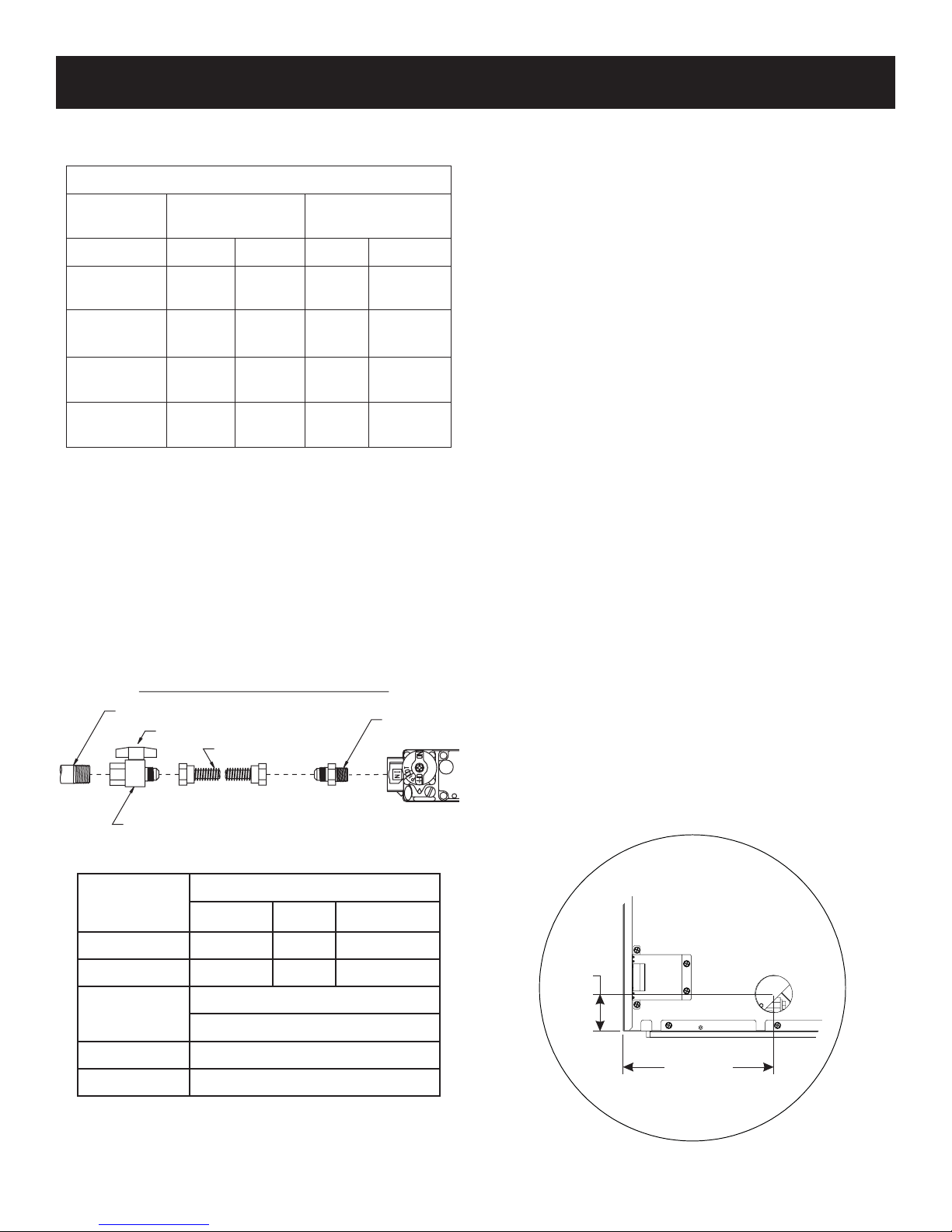
GAS SUPPLY
The gas pipeline can be brought in through the left side of the
appliance.ConsultthecurrentNationalFuelGasCode,ANSIZ223.1
CAN/CGA-B149(.1or.2)installationcode.
Recommended Gas Pipe Diameter
Pipe Length Schedule 40 Pipe
Inside Diameter
Tubing, Type L
Outside Diameter
Nat. L.P. Nat. L.P.
0-10ft
0-3m
1/2in.
12.7mm
3/8in.
9.5mm
1/2in.
12.7mm
3/8in.
9.5mm
11-40ft
4-12m
1/2in.
12.7mm
1/2in.
12.7mm
5/8in.
15.9mm
1/2in.
12.7mm
41-100ft
13-30m
1/2in.
12.7mm
1/2in.
12.7mm
3/4in.
19mm
1/2in.
12.7mm
101-150ft
31-46m
3/4in.
19mm
1/2in.
12.7mm
7/8in.
22.2mm
3/4in.
1.9mm
Note:Neveruseplasticpipe.Checktoconrmwhetheryourlocal
codesallowcoppertubingorgalvanized.
Note:Sincesomemunicipalitieshaveadditionallocalcodes,itis
alwaysbesttoconsultyourlocalauthorityandinstallationcode.
Theuseofthefollowinggasconnectorsisrecommended:
— ANSZ21.24ApplianceConnectorsofCorrugatedMetalTubing
andFittings.
— ANSZ21.45AssembledFlexibleApplianceConnectorsofOther
ThanAll-MetalConstruction
Theaboveconnectorsmaybeusedifacceptablebytheauthority
having jurisdiction. The state of Massachusetts requires that a
exibleapplianceconnectorcannotexceedthreefeetinlength.
▲
►
▼
◄
◄
FLEXIBLE GAS LINE CONNECTION
GAS SUPPLY
TEE HANDLE
FLEX TUBING
FLARE SHUT OFF VALVE
FLARE
FITTING
Figure 7
GasSupplyPressure(inchesw.c.)
Minimum Normal Maximum
NaturalGas 5.0 7.0 14.0
LP(Propane) 10.8 11.0 14.0
ManifoldPressure(inchesw.c.)
Normal(HI)
NaturalGas 3.5
LP(Propane) 10.0
Installing a New Main Gas Cock
Eachapplianceshouldhaveitsownmanualgascock.
Amanualmaingascockshouldbelocatedinthevicinityoftheunit.
Wherenoneexists,orwhereitssizeorlocationisnotadequate,
contactyourlocalauthorizedinstallerforinstallationorrelocation.
Compoundsusedonthreadedjointsofgaspipingshallberesistant
totheactionofliqueedpetroleumgases.Thegaslinesmustbe
checkedforleaksbytheinstaller.Thisshouldbedonewithasoap
solutionwatchingforbubblesonallexposedconnections,andif
unexposed,apressuretestshouldbemade.
Never use an exposed ame to check for leaks. Appliance must
be disconnected from piping at inlet of control valve and pipe
capped or plugged for pressure test. Never pressure test with
appliance connected; control valve will sustain damage!
NOTE:Thegascontrolsareequippedwithacapturedscrewtype
pressuretestpoint,thereforeitisnotnecessarytoprovidea1/8in.
testpointupstreamofthecontrol.
Whenusingcopperorexconnectoruseonlyapprovedttings.
Theapplianceanditsindividualshutoffvalvemustbedisconnected
fromsupplypipingsystemduringanypressuretestingofthatsystem
attestpressuresinexcessof1/2psig(3.5kPa).
Theappliancemustbeisolatedfromthegassupplypipingsystem
byclosingitsindividualmanualshutoffvalveduringanypressure
testingofthegassupplypipingsystemattestpressuresequalto
orlessthan1/2psig(3.5kPa).
Attention!Ifoneoftheproceduresresultsinpressuresinexcess
of1/2psig(14in.w.c.)(3.5kPa)onthereplacegasvalve,itwill
resultinahazardouscondition.
Checking Manifold Pressures
Both Propane and Natural gas valves have a built-in pressure
regulatorinthegasvalve.Naturalgasmodelswillhaveamanifold
pressureofapproximately3.5in.w.c.(.871kPa)atthevalveoutlet
withtheinletpressuretothevalvefromaminimumof5.0in.w.c.
(1.245kPa)forthepurposeofinputadjustmenttoamaximumof
14.0in.w.c.(3.484kPa).Propanegasmodelswillhaveamanifold
pressure approximately 10.0 in. (2.49kPa) at the valve outlet
withtheinletpressuretothevalvefromaminimumof10.8in.w.c.
(2.68kPa) for the purpose of input adjustment to a maximum of
14.0in.w.c.(3.484kPa).
2-7/16”
(61 mm)
8-1/4”
(209.5mm)
Figure 8

33598-6-0115 Page 11
Vent Pipe Clearance
Note:Maintainoneinch(1in.)ofclearancearoundverticalvent
pipe.See Figure 9.Forhorizontalvent,maintainaminimum1in.
clearancetothebottom,twoinchestothesidesofthevent,and3
in.clearancetocombustiblesabovetheventpipe.See Figure 10.
►
◄
VENT PIPE
1” (25mm) MINIMUM
CLEARANCE AROUND VENT PIPE
Figure 9
2” (50.8mm)
TOP OF VENT PIPE
4”
DIAMETER
FLUE
6-5/8”
DIAMETER
INTAKE VENT
3” (76mm)
1”
(25.4mm)
Figure 10
INSTALLATION
Attention: Horizontal venting through a wall requires a wall
thimbleontheinteriorsideofthewallabovethepipe.
SPECIAL VENT SYSTEMS
ThefollowingventsystemsareacceptableforusewithDV(TL,LL)41FPseriesreplaces:
Simpson Duravent® GS 4" - 6 5/8"
Selkirk Direct-Temp® 4" - 6 5/8"
Security Secure Vent® 4" - 6 5/8"
EmpireFlexventKitDVVK-4F,refertopage30.
33598-6-0115Page 12
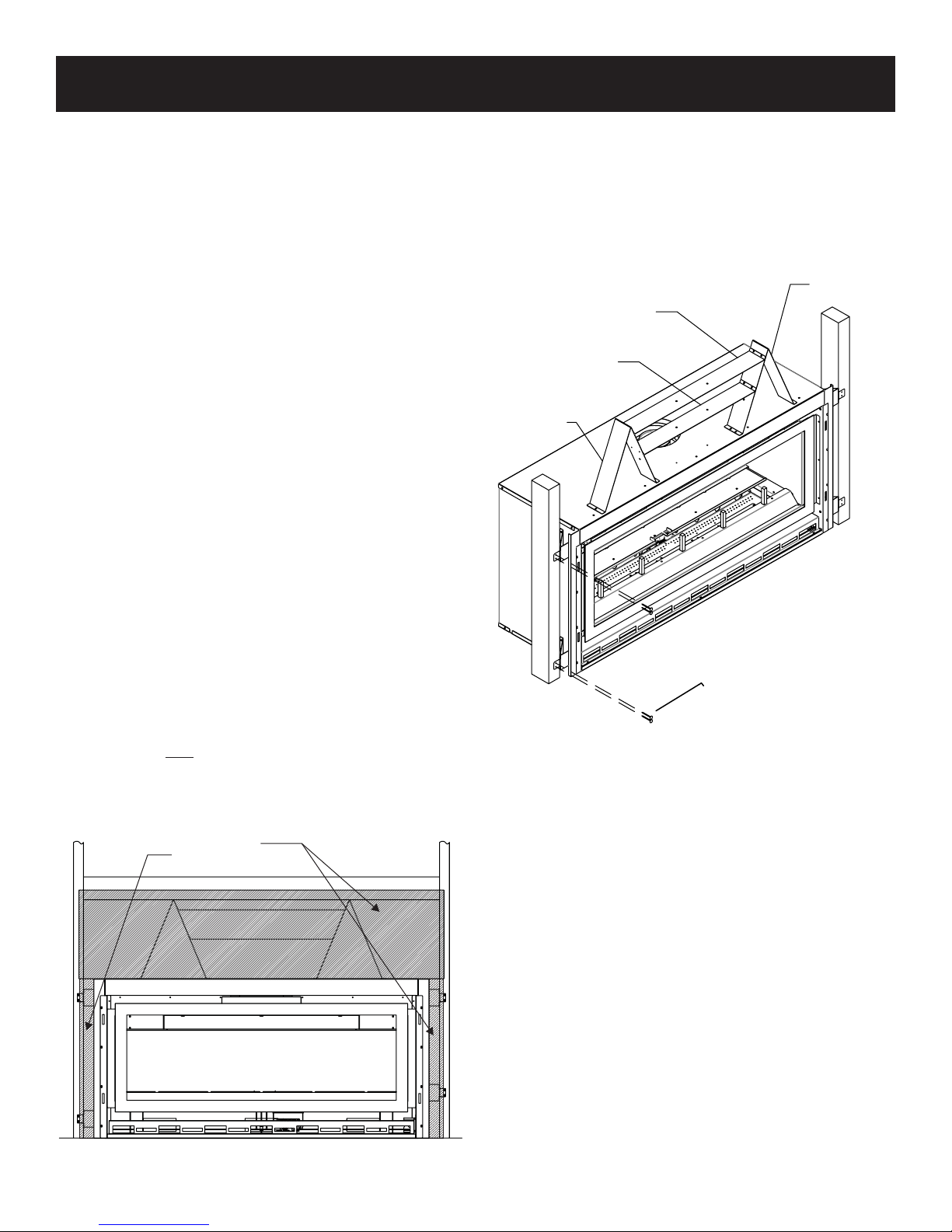
INSTALLATION
Framing and Finishing
NOTE: You must use the standoffs that are supplied with the
replace. The standoffs are shipped in a at-state on top
of the replace.
1. Locatethetwo(2)steelstandoffsandtwo(2)headershields
attachedtothebackofthereplace.
2. Removethetwo(2)screwsthatsecurethestandoffsandheader
shieldsinplace;savethescrews.
3. Therightandleftstandoffshaveaperforationlocatedinthe
middle.Bendthemattheperforationtoalittlemorethan90°.
4. Bendtheshorttabsoneachendtheoppositedirection.Secure
thestandoffstothereplacetopwiththree(3)screwseach
fromthehardwarebag.Therearepilotholeslocatedinthe
topofthereplaceforeachstand-off.
5. Verifythatthefrontofthestandoffsare1/2in.(13mm)back
from the face of the replace. Verify that the stand-off is
12in.(305mm)tall.
6. Locatethebottomheadershield;itistheshorterone.Using
four(4)screws,attachitbetweenthestandoffs.
7. Locatethetopheadershield;itisthelongerone.Usingfour
(4)screws,attachitbetweenthestandoffs.See Figure 12.
8. Removethenon-combustibleboardthatisshippedbetween
thereplaceandpallet.
9. Frameinreplacewithaheaderacrossthetop.
IMPORTANT:Allowfornishedfacewhensettingthedepth
oftheframe.
10. Attachthereplacetotheframing.See Figure 12.
11. Installthenon-combustibleboardacrossthetopandsidesof
thereplace.Theboardsitsonthe1/2in.surfaceontopofthe
replaceandinfrontofthestandoffs.See Figure 11.
IMPORTANT: IN ORDER TO USE SOME OPTIONAL FRONTS
YOU MUST RAISE THE FIREPLACE ON A HEARTH SO THE
BOTTOM OF THE FIREPLACE IS A MINIMUM DISTANCE
ABOVE THE TOP OF THE HEARTH EXTENSION FINISHING
MATERIAL. CHECK DECORATIVE FRONT DIMENSIONS
PRIOR TO SETTING THE HEIGHT OF THE FIREPLACE
HEARTH EXTENSION.
NON-COMBUSTIBLE
BOARD
Figure 11
Flush Mount Mantel Installation
The fireplace must extend 3/4 in. (19mm) beyond finished
wall surface when using a ush mount mantel. Refer to Figure
12 to locate nailing anges on replace sides. Mark and drill
four (4) 1/8 in. holes into replace side to mount each nailing
flange. Use eight (8) 1/2 in. hex-head screws supplied in
hardware package to attach nailing anges to replace sides.
◄
▼
▼
STAND-OFF
STAND-OFF
TOP
HEADER SHIELD
BOTTOM
HEADER SHIELD
NAIL OR OTHER SUITABLE
FASTENER
▼
Figure 12

33598-6-0115 Page 13
Finishing
Finishthewallswiththematerialofyourchoice.Figure4onpage8
showstheminimumverticalandcorrespondingmaximumhorizontal
dimensionsofmantelsorothercombustibleprojectionsabovethe
topfrontedgeofthereplace.Onlynon-combustiblematerialsmay
beusedtocoverthemetalreplaceface.
Flush Wall Installation
▼
►
▼
▼
HEADER: A DOUBLE HEADER
OR PLACING THE HEADER
VERTICALLY IS RECOMMENDED
STANDOFF 12” (305mm)
HEIGHT ABOVE TOPOF
THE FIREPLACE
FIRST 13-1/2” (343mm)
NON-COMBUSTIBLE
FINISHED WALL
TOP OF THE
FIREPLACE
Figure 14
Combustible Surround Installation
COMBUSTIBLE MANTLE
FINISHED WALL
2 X 4 HEADERS
STANDOFFS
NON-COMBUSTIBLE MA
TERIAL
13-1/2” (343mm)
NON-COMBUSTIBLE MA
TERIAL
SUPPLIED WITH FIREPLACE
Figure 15
Framing
Fireplaceframingcanbebuiltbeforeorafterthereplaceisset
inplace.Framingshouldbepositionedtoaccommodatewall
coveringandreplacefacingmaterial.Thereplaceframing
shouldbeconstructedof2x4lumberorheavier.Theframing
headersmayrestonthereplacestandoffs.Refer to Figure 13
for minimum framing dimensions.
CAUTION: MEASURE FIREPLACE DIMENSIONS AND VERIFY
FRAMING METHODS,AND WALL COVERING DETAILS BEFORE
FRAMING CONSTRUCTION BEGINS.
B
C
A
DVLL/DVTL
A36-7/8in.(937mm)
B54-1/2in.(138.4cm)
C17-1/16in.(433mm)
Figure 13
Framing dimension "A" includes a 12 in. (304 mm)
clearance for standoffs on rebox. After installing rebox
into framing, the nished wall surface must cover the
12 in. (304mm) opening above the rebox. Board provided
with replace.
ATTENTION: Ifabaseormantelisnotusedandtheapplianceis
installeddirectlyoncarpeting,tileorothercombustiblematerialother
thanwoodooring,itshallbeinstalledonametalorwoodpanel
extendingthe fullwidthanddepthof theappliance.Thevertical
dimensioninFigure 13mustbeadjustedwhenametalorwood
panelisplacedbeneaththeappliance.
CAUTION:Ifthejointsbetweenthenishedwallandthereplace
surround (top and sides) are sealed, a 300°F minimum sealant
materialmustbeused.Thesejointsarenotrequiredtobesealed.
Onlynon-combustiblematerial(using300°Fminimumadhesiveif
needed),canbeappliedasfacingtothereplacesurround.
INSTALLATION

33598-6-0115Page 14
Attention: Cold climate installation recommendation:
When installing this unit against a non-insulated exterior
wall, it is recommended that the outer walls be insulated to
conform to applicable insulation codes.
Vent Runs
Inplanningtheinstallationforthereplace,itisnecessarytoinstall
certaincomponentsbeforetheapplianceiscompletelypositioned
andinstalled.Theseincludethedirectventsystem,gaspipingfor
theapplianceandtheelectricalwiring.
Theappliancecanbemountedonanyofthefollowingsurfaces:
1. Aat,hardcombustiblesurface.
2. Araisedwoodenplatform.
3. Four(4)cornersupports.(Example:Four(4)concretemasonry
blocks.)Thesesupportsmustbepositionedsotheycontactall
four(4)perimeteredgesonthebottomoftheunitandunderthe
centerlegsupports.Twomoresupportsspacedevenlyforfront
andbackmayberequiredpendinglocalcode.
Vertical, 90° Elbow With Horizontal Termination
3” (76mm)
MINIMUM CLEARANCE
TO COMBUSTIBLES
57-3/4”
(146.7cm)
VENT CAP/THIMBLE
WALL FIRESTOP
Figure 16
IMPORTANT:
MINIMUM HEIGHT OFF THE TOP REQUIREMENTS
DVLL & DVLT -MUSTUSEa2ft.(610mm)verticalventpipeas
therstsectionBEFOREinstallingtheelbow.
Vertical, 90° Elbow To
Horizontal Out The Wall
◄
►◄
►
◄
◄
90°
ELBOW
VENT
CAP
WALL
FIRESTOP
A
PIPE LENGTH
B
C
A B C
6in. 11-3/4in.to12-3/4in.
(298mmto323mm)
4-3/4in.to6-1/4in.
(121mmto159mm)
9in. 14-1/4in.to15-3/4in.
(362mmto400mm)
7-3/4in.to9-1/4in.
(197mmto235mm)
12in. 17-1/4in.to18-3/4in.
(438mmto476mm)
10-3/4in.to12-1/4in.
(273mmto311mm)
Figure 17
VENTING FIREPLACE

33598-6-0115 Page 15
Maximum Horizontal Run For A Minimum Vertical Rise
20” (50.8 cm)
MAXIMUM
24” (609.6mm)
MINIMUM VENT
PIPE LENGTH
Figure 19
Minimum Vertical Rise For Maximum Horizontal Run
20’
(6.1M)
8’ (243.8cm)
TO TOP
OF UNIT
Figure 20
Corner Installation Vertical, 90° Elbow
To Horizontal Out The Wall
▲
►
▼
◄
►
▼
▲
►
▼
◄
◄
B
A
C
◄►
E
D
*
NOTE: YOU MUST USE A2’ (609.6mm) VERTICAL
VENT PIPE
AS YOUR FIRST SECTION BEFORE
INST
ALLING THE ELBOW.
VENT CAP
THIMBLE
WALL
FIRESTOP
*
DVLL/DVTL
A62-1/4in.
(158.1cm)
B44-1/16in.
(111.9cm)
C24-5/8in.
(62.6cm)
D88-1/16in.
(223.7cm)
E24in.
(60.9mm)
Figure 18
Note:Cornerinstallationmayrequiremoreverticalventpipe
thanjusttheminimumrequireddependingonwallthicknessand
horizontaldimension.
VENTING FIREPLACE

33598-6-0115Page 16
EXAMPLE A:
Iftheverticaldimensionfromthetopoftheunitis35ft.(10.67m),the
horizontalruntotheouterwallangemustnotexceed5ft(1.52m).
EXAMPLE B:
Iftheverticaldimensionfromthetopoftheunitis5ft.(1.52m),the
horizontalruntotheouterwallangemustnotexceed11ft.(3.35m).
Special Note: Foreach45degreeelbowinstalledinthehorizontal
run, the length of the horizontal run MUST be reduced by 18"
(45cm).Thisdoesnotapplyifthe45degreeelbowsareinstalled
ontheverticalpartoftheventsystem.Reduce3ft.(91.4cm)for
every90°elbow.
Example:Accordingtothechartthemaximumhorizontalventlength
is20ft.(6.10m)andiftwo45degreeelbowsarerequiredinthe
horizontalventitmustbereducedto17ft.(5.18m).
The maximum number of 45 degree elbows permitted per side
wallinstallationistwo.Theseelbowscanbeinstalledineitherthe
verticalorhorizontalrun.
NOTE:Therstelbowdoesnotgetcounted.
Vertical Venting
Whenventinglongstraightverticalsections,useoftheverticalvent
bafesmayberequiredforoptimalameperformance.
Toinstallverticalventbafes,alignthetwoholesonthevertical
ventbafewiththetwoholesintheuebafe.Securethevertical
ventbafewiththescrewsprovided.Repeatforbothsidesofthe
uebafe.
Figure 22
VENTING FIREPLACE
To Use the Vent Graph
1. Determinetheheightofthecenterofthehorizontalventpipe.
Usingthis dimensiononthe SidewallVentGraph, locatethe
pointitintersectswiththeslantedgraphline.
2. Fromthepointof thisintersection,drawavertical linetothe
bottomofthegraph.
3. Selecttheindicateddimension,andpositiontheunitinaccordance
withsame.
Acceptableverticalandhorizontalventrun.
(40ft.(12.19m)maximumverticaland20ft.(6.10m)maximum
horizontal)
Unacceptableverticalandhorizontalventrun.
Figure 21

33598-6-0115 Page 17
Example Of Possible Venting System Using One 90° Elbow
8 ft. (2.44 m) is listed as minimum vertical vent run with 20 ft.
(6.10m)ofmaximumhorizontalventrun.Verticaldimensionsare
basedoncenterlinetocenterlineofpipe.Horizontaldimensionsare
basedoncenterlineofpipetoexteriorofwall.
FIRE STOP AT
CEILING LEVEL
H
V
SEE GRAPH (Figure 21) FOR PERMISSIBLE
"H" AND "V" DIMENSIONS
Figure 24
Below Grade Installation
Whenitisnotpossibletomeettherequiredventterminalclearances
of12in.(305mm)abovegradelevel,asnorkelkitisrecommended.
Itallowsinstallationdepthdownto7in.(178mm)belowgradelevel.
The7in.(178mm)ismeasuredfromthecenterofthehorizontal
ventpipeasitpenetratesthroughthewall.
Ensure the sidewall venting clearances are observed. If venting
system is installed below ground, we recommend a window
well with adequate and proper drainage to be installed around
the termination area.
Typical Basement Installation
18”
(457mm)
MINIMUM
3” (76mm)
MINIMUM
COMBUSTIBLE
PROJECTION
PIPE STRAP
48”
(121.9cm)
12”
(305 mm)
ABOVE GRADE
Figure 23
VENTING FIREPLACE

33598-6-0115Page 18
Example Of Possible Venting System Using Two (2) 90° Elbows
Examplesofpossibleventingsystemsusingtwo(2)90°elbows.
VislistedasminimumverticaldimensionsandH1+H2islisted
astotalofmaximumhorizontaldimensions.Themaximumvertical
andhorizontaldistancesfortwo(2)90°elbowsasshownin Figure
25is37ft.(11.28m).
FIRE STOP AT
CEILING LEVEL
H1
H2
V
SEE GRAPH (Figure 21) FOR PERMISSIBLE
"H" AND "V" DIMENSION
NOTE: H1 AND H2 MUST BE ADDED TOGETHER TO USE
GRAPH THEN SUBTRACT 3' (91.4 cm) FOR THE SECOND
90° ELBOW
Figure 25
VENTING FIREPLACE

33598-6-0115 Page 19
VENT CAP
9” (229 mm)
MINIMUM TO SIDE WALL
Figure 27
VENTING FIREPLACE
10”
(254mm)
12”
(305mm)
A
CENTER OF FRAMING
(MINIMUM VENT)
V
CENTER
OF ELBOW
H
C
B
C
B
Figure 26
MINIMUM HOLE LOCATION DIMENSIONS FOR THROUGH THE
WALL HORIZONTAL INSTALLATIONS WITH 90 DEGREE ELBOW
OFF TOP OF FIREPLACE
Positioning the Fireplace
FIREPLACE
SERIES
HARD ELBOW DIMENSIONS
A B C
DVLL/DVTL 55-5/8in.
(141.3cm)
5in.
(127mm)
7in.
(178mm)
Determinethe exactposition ofthe applianceso thedirect vent
terminationwillbecentered(ifpossible)betweentwo(2)studs.This
willavoidanyextraframing.Allventkitpipesshouldbeassembled
ontheunitaftertheunitismovedintothenalposition.
Cutting the Hole
Afterthereplacehasbeenpositionedinitspermanentlocation,
theholethroughtheexteriorwallofthehousecanbecut.Thishole
mustbe12in.(305mm)highx10in.(254mm)widewithitscenter
linedeterminedbytheamountofverticalriseandhorizontalrunof
thetermination.See Figure 26. Whenlocatingtheholeitmustbe
notedthatthebottomofthecapmustbe12in.(305mm)abovethe
groundlevel,andtopofthecapmustbenolessthan18in.(457mm)
belowacombustibleprojection,andnocloserthan9in.(229mm)
toanywallrunningparalleltoventtermination.See Figure 27.

33598-6-0115Page 20
24”
(61 cm) MINIMUM CLEARANCE
TO COMBUSTIBLES
H1 H2
V1
Figure 28
H1 H2
V1
EXAMPLES - TOP VENT RUN
Iftotalhorizontalneedstobe8'(2.44m),thentheminimum
requiredverticalis5'(1.52m).
H=8'(+90°)=11'(equivalenthorizontal)
H=2.44m(+90°)=2.44m(equivalenthorizontal)
Fromthegraphtherequiredverticalis5'(1.52m). Figure 29
Iftotalhorizontalneedstobe10'(3.05m),thentheminimum
requiredverticalis7'(2.13m).
H=10'(90°+90°)=16'(equivalenthorizontal)
H=3.05m(90°+90°)=4.88m(equivalenthorizontal)
Fromthegraphtherequiredverticalis7'(2.13m).
This manual suits for next models
5
Table of contents


