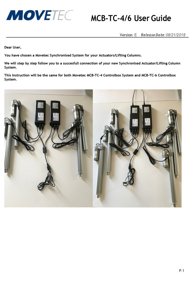
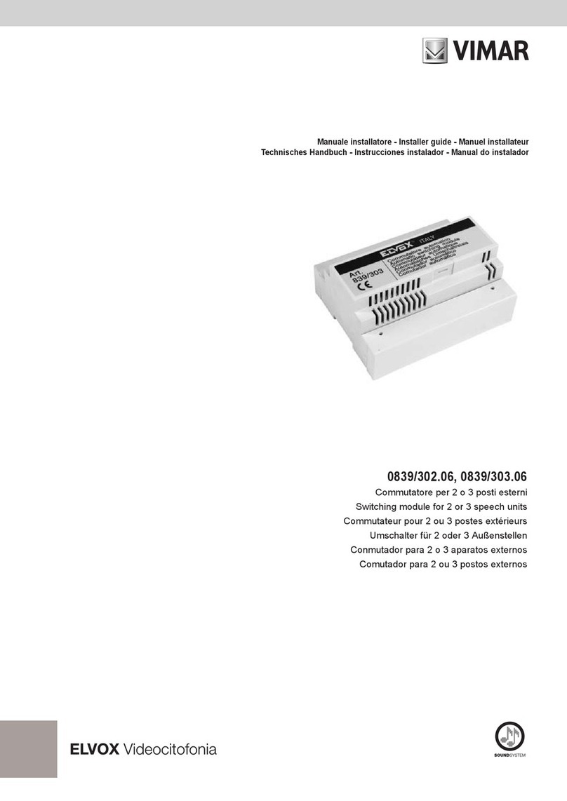
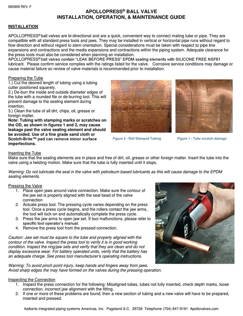
belven BV10S Series Manual

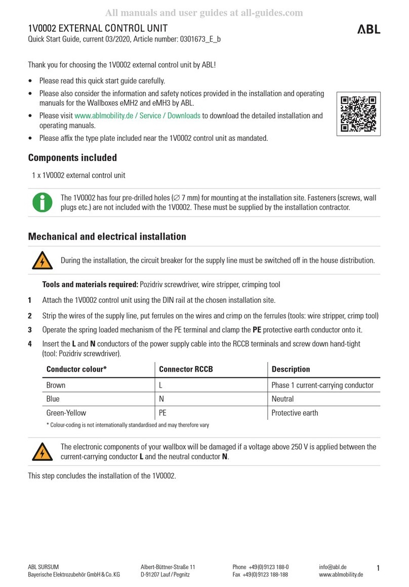
IOM BV10S -BV12S/ 20180522
Belven NV Blokhuisstraat 24 2800 Mechelen Belgium
Tel. +32 (0)15 29 40 70 Fax +32 (0) 15 20 14 13
info@belven.com www.belven.com
Pagina 1 van 15
We keep the right to change above mentioned information at any time without any prior or direct notice
1. Storage & Protection
Always visually inspect the valves at reception to determine if any damage has occurred during
shipping. Inspect the body for cracks or holes. For proper operation of the valves, the seat and disc
seal must be undamaged and free of foreign material. If damage is discovered, contact Belven
immediately, indicating the location and extent of the damage found, photographs of the packing and
damages are appreciated.
The Belven valves must be stored with the disc cracked off the seat (approx..10°). The connections
must be covered to protect the flange faces and internals for dust, dirt, oil or other impurities.
Store the valves indoors at a cool temperature between -4°C and 30°C in a dry place that is fire
resistant, weather tight and well ventilated. No corrosive chemicals should be present.
When an electric- or pneumatic actuator is mounted on the valve we recommend that it should be
cycled approximately every 30 days.
Any spare parts for the valve shall be stored in the original packaging and under the same conditions
as the valve is stored.
For storage longer than 4 months, the storage container should be inspected every four (4) months to
ensure it is in good condition, and any additional protective coverings or materials are in working order.
Ensure all parts are plugged, and bare metal is covered with a suitable rust inhibitor. The seat should
be coated with a suitable lubricant.
Avoid storage under direct sun exposure.
Do not stack unpacked valves.
After a long-term storage clean the Belven valve, especially the sealing surfaces, control that the
rubber seat is not dried out and check the valve tightness before installation.
INSTALLATION, OPERATION AND MAINTENANCE INSTRUCTIONS TYPE BV10S & BV12S

IOM BV10S -BV12S/ 20180522
Belven NV Blokhuisstraat 24 2800 Mechelen Belgium
Tel. +32 (0)15 29 40 70 Fax +32 (0) 15 20 14 13
info@belven.com www.belven.com
Pagina 2 van 15
We keep the right to change above mentioned information at any time without any prior or direct notice
Do not toss the valves and do not lift the valves by the lever, gearbox or actuator.
While moving large valves nylon slings, secured around the valve bearing areas, are recommended to
reduce the possibility of mechanical damage occurring to the valve body and actuator.
Please respect the lifting method as in below drawings.
2. Cautions
FOR SAFETY, FOLLOW THESE CAUTIONS BEFORE INSTALLING, REMOVING OR
DISASSEMBLING THE VALVE.
1. THE OPERATION OF BUTTERFLY VALVES AND THEIR CONTROLS MUST BE DONE BY
STAFF TRAINED IN ALL ASPECTS OF THEIR OPERATION
2. KNOW WHAT MEDIA IS IN THE PIPELINE.
3. MAKE SURE THE LINE IS DEPRESSURIZED.
4. USE PROTECTIVE CLOTHING AND EQUIPMENT TO AVOID INJURY. KEEP HANDS AND
OTHER BODY PARTS OUT OF THE VALVE.
5. ALWAYS ENSURE THE VALVE DISC IS FULLY INSIDE THE VALVE BODY BEFORE
INSTALLATION, REMOVAL OR DISASSEMBLY.
6. THE OUTER EDGE OF THE DISC IS DELICATELY FABRICATED TO ENSURE AN EXCELLENT
SEALING WITH THE RUBBER SEAT. PLEASE BE CAREFUL NOT TO DAMAGE THESE
SURFACES WHILE INSTALLING OR HANDLING THE VALVE.
7. CLEAN OFF THE FLANGE FACES BEFORE INSTALLATION IN THE PIPELINE.

IOM BV10S -BV12S/ 20180522
Belven NV Blokhuisstraat 24 2800 Mechelen Belgium
Tel. +32 (0)15 29 40 70 Fax +32 (0) 15 20 14 13
info@belven.com www.belven.com
Pagina 3 van 15
We keep the right to change above mentioned information at any time without any prior or direct notice
3. Installation
3.1. Warning Precautions
MAKE SURE THE VALVE CAN FULFILL THE REQUIREMENT OF THE PIPE EQUIPMENT.
The properties of the fluid in the valve, such as pressure, temperature, nature of the fluid must be
considered.
The Belven valves carry our label with our logo, our website, the Belven product type, the size, the
pressure class, body material, disc material, seat material, QR-code to our website and CE marking.
Always ensure that the requirements are within the range of the valve and the seat material.
Example:
And a separate label for the serial number
Example:
The serial number indicates the year of production and makes the valve retraceable to its production
order and sales order.
Always ensure that the requirements are within the range of the valve and the seat material.

IOM BV10S -BV12S/ 20180522
Belven NV Blokhuisstraat 24 2800 Mechelen Belgium
Tel. +32 (0)15 29 40 70 Fax +32 (0) 15 20 14 13
info@belven.com www.belven.com
Pagina 4 van 15
We keep the right to change above mentioned information at any time without any prior or direct notice
Below you find our seat overview with temperature and pressure limits.
Above mentioned ratings are for static non-shock conditions.
Above mentioned maximum temperature is suitable for maximum 1 bara working pressure. The
maximum allowable temperature will decrease as the working pressure increases.
Vacuum applications should be verified with Belven before ordering and the max. vacuum pressure of
the application should be explicitly mentioned on the purchase order.
MATERIAL
COLOR
CODE
SEATCODE
DENOMINATION
ISO1629
MINIMUM
TEMPERATURE°C
MAXIMUM
TEMPERATURE°C
MAX.PRESSUREPN16
VALVE
MAX.PRESSUREPN10
VALVE
EPDM‐ E
EPDM
‐15 120 16bar 10bar
FOODWHITEEPDM‐ WE ‐10 90
DN50‐DN150:10bar
DN200‐DN300:6bar
DN50‐DN150:10bar
DN200‐DN300:6bar
EPDM‐HT WHITE HE ‐20 130 16bar 10bar
EPDM‐HT(FDA)‐ EF ‐10 130 16bar 10bar
NITRILE‐ B
NBR
‐10 90 16bar 10bar
FOOD WHITENITRILE‐ WB ‐10 90 16bar 10bar
NBRGAS(DVGW) ‐ NG ‐10 90 16bar 10bar
HYDROGENATEDNBR‐ Z HNBR‐10 90 16bar 10bar
LOWTEMPER.NITRILE‐ NL NBR‐20 90 16bar 10bar
EPICHLORHYDRIN‐ CH ECO‐40 90 16bar 10bar
HYPALON‐ H CSM‐10 100 16bar 10bar
VITONRED V
FPM
‐5 200 16bar 10bar
VITONGF‐ VG ‐5 200 16bar 10bar
VITONBIOYELLOW VB ‐5 200 16bar 10bar
VITONLOWTEMPER.‐ VL ‐30 200 16bar 10bar
VITONBASES‐ V2 ‐5 200 16bar 10bar
FOODVITON‐ VF ‐5 200 16bar 10bar
SILICONE‐ Q
MVQ
‐55
200
10bar 10bar
FOODSILICONE‐ QF ‐55 10bar 10bar
STEAMSILICONEORANGE S ‐55 160 6bar 6bar
FLUORSILICONE‐ QO FMVQ‐55 200 10bar 10bar
AB/E ‐ FW ‐‐5 90 16bar 10bar
AB/P GREY FC ‐‐10 70 16bar 10bar
AB/N ‐ FO ‐0 90 16bar 10bar
AB/T ‐ FH ‐‐5 130 16bar 10bar

IOM BV10S -BV12S/ 20180522
Belven NV Blokhuisstraat 24 2800 Mechelen Belgium
Tel. +32 (0)15 29 40 70 Fax +32 (0) 15 20 14 13
info@belven.com www.belven.com
Pagina 5 van 15
We keep the right to change above mentioned information at any time without any prior or direct notice
Waterhammer and impact should be avoided.
Always ensure that the operation conditions comply with those specified on the drawing or datasheet.
The valves must be installed and operated in accordance with the local requirements and regulations of
industrial valves. Any violation of these regulations may become dangerous for health, environment or
the installation. Belven shall not bear responsibility for wrong installation or operation of its valves.
Before installation of the valve into the piping system, visually inspect the valve to determine if any
damage has occurred during storage or transport to site. For proper operation of the valves, the seat
and disc seal must be undamaged and free of foreign material. No cracks may appear in the body. If
the rubber seat is dried out (for example due to long storage) we recommend lubricating it with a
suitable grease or to replace it by a new seat. If damage is discovered, contact Belven immediately,
indicating the location and extent of the damage found
If it is necessary to clean the valve, use a soft cloth and an appropriate solvent. Be aware not to affect
the resilience of the rubber seat.
BE AWARE OF DISC CUTTING MOVEMENT
Keep hands, tools and other objects out of the open port and leave no foreign objects inside of the
pipeline. When the valve is actuated the disc functions as a cutting device. The position of the disc can
also change when moving the valve. Always ensure the disc can’t move during maintenance, always
move an actuator to its rest position and detach the pressure supply line and/or electrical supply before
performing any maintenance.

IOM BV10S -BV12S/ 20180522
Belven NV Blokhuisstraat 24 2800 Mechelen Belgium
Tel. +32 (0)15 29 40 70 Fax +32 (0) 15 20 14 13
info@belven.com www.belven.com
Pagina 6 van 15
We keep the right to change above mentioned information at any time without any prior or direct notice
3.2. Installation Procedures
Tests and inspections of the open and closed valve are necessary to see whether there is any trouble to
open/close the valve.
Prior to installation the pipeline must be cleaned from dirt and welding residues to avoid damage of the
valve during operation. The pipe needs to be depressurized and cold (e.g. no installation immediately
after pipe flange welding). The valves are suitable to be mounted between flanges EN 1092-2 and EN
1759-1 flanges. Ensure that the inside diameter of the adjacent pipe flange is large enough for the disc
to turn in fully open position without touching the flange or pipe. The outer edge of the disc may not
touch the flanges nor the piping to prevent damages.
The flanges facing of the adjoining pipework should be checked for correct size and contact face and
clean surface. All rust and dirt must be removed from the flange facings to prevent damage of the valve
seat and leakage after installation. We recommend using metal connection flanges to install our BV10S
and BV12S valve. Parallel alignment of the flanges is required for a proper installation of the valve. If a
condition is found which might cause leakage, it should be corrected before any attempt of installation.
The Belven BV10S-BV12S valve seat serves as gasket between the valve body and the connecting
flanges. No additional gaskets are necessary, they can cause over-compression and distortion of the
seat resulting in higher operating torques and premature seat wear.

IOM BV10S -BV12S/ 20180522
Belven NV Blokhuisstraat 24 2800 Mechelen Belgium
Tel. +32 (0)15 29 40 70 Fax +32 (0) 15 20 14 13
info@belven.com www.belven.com
Pagina 7 van 15
We keep the right to change above mentioned information at any time without any prior or direct notice
Set jack bolts or other flange spreaders to maintain the gap between the flanges to insert the valve. The
distance between the flanges should be 10mm wider than the valve body. The valve must be inserted
without interference with the flanges.
Ensure that the valve disc is inside the valve body prior to installation. We recommend the disc should
be about 10° in the open position. This way the disc stays inside the face of the seat preventing the disc
edges being damaged during installation. Do not fully close the valve, this may cause a compression
set to the seat creating higher operating torques and shorten the life time of the seat. Take special care
for valves with single acting actuators. We supply the valves with an air failure closed actuator with the
disc in fully closed position and valves with an air failure open actuator with the disc in fully open
position. Taken into account above mentioned remarks about damaging the disc edge or increasing the
operating torques or premature seat failure we recommend dismounting the actuators and putting the
valve disc on 10° before installing the valve: first mark actuator and valve and shaft (for proper
re-assembly of the actuator), dismount the actuator, install the valve properly and put the valve disc in
the correct original position and the re-mount the actuator in the correct configuration on the valve.
Never lift the valves by their lever, gearbox or actuator.
Carefully place the valve between the flanges, center it and insert the bolts through the lugs of the valve
but do not tighten the bolts yet. Slowly open the disc and ensure the disc does not touch the inside of
the connection flange or adjacent pipe.
Remove the jack bolts (flange spreaders) and hand tighten the bolts as per opposite angles respecting
further mentioned bolt tightening sequence.

IOM BV10S -BV12S/ 20180522
Belven NV Blokhuisstraat 24 2800 Mechelen Belgium
Tel. +32 (0)15 29 40 70 Fax +32 (0) 15 20 14 13
info@belven.com www.belven.com
Pagina 8 van 15
We keep the right to change above mentioned information at any time without any prior or direct notice
BOLT TIGHTENING SEQUENCE
Carefully close the valve disc to ensure proper clearance.
Open the valve disc and repeat the bolt tightening sequence ensuring a balanced tightening.
Do not over-tighten the valve and respect the max. torque of the bolts.
Re-check the disc can fully open/close without any obstruction.
We recommend mounting the valve with the stem in upright vertical position with the actuator on top of
the valve, with exception of applications with slurries or with particles for which we recommend to install
the valve with the shaft in horizontal position. In this way slurries will pass under the disc and will be
pushed away outside the valve.
We do not recommend installing the valves upside down.
Do not install the valves in a pipe bend or too close to pumps or other pipe elements to avoid
turbulences. Belven recommends that the length of straight pipe preceding the BV10S or BV12S
butterfly valves is at least 6x the pipe diameter. This distance is not always practical, but it is important
to respect it as much as possible to avoid premature failure and life cycle reduction. Always use an
expansion joint between pump and butterfly valve or check valve and butterfly valve.
Wafer type valves shall not be installed at the end of a pipe, they need a counter flange with extension tube.
Ensure that the valve and connection flanges are precisely aligned.
Test cycle the valve to be sure that there is no interference or clogging.
The pipes must be connected with the valve without generating tension.
When necessary support the pipeline to protect the valve from excess stress. Tensions should be
cushioned by expansion joints or compensators. If supports are necessary for the valve, they should
only support the dead weight of the valve and should not serve as base points for the pipeline.

IOM BV10S -BV12S/ 20180522
Belven NV Blokhuisstraat 24 2800 Mechelen Belgium
Tel. +32 (0)15 29 40 70 Fax +32 (0) 15 20 14 13
info@belven.com www.belven.com
Pagina 9 van 15
We keep the right to change above mentioned information at any time without any prior or direct notice
When a lug type valve is used as end-of-line valve and it will be pressurized, a counter flange should be
mounted to prevent personal injuries at leakages or unallowed opening of the valve.
While opening the disc turns out of the valve body and might cause injuries.
Always ensure the valve is completely mounted on both sides before operating the valve.
Before putting the system into service, flush it with water. Cleaning by air blowing
can be done on the outer surface of the piping system.
Pressurize the system and check for any leak by applying soapy water to them.
If leakage is found, check if all bolts are evenly torqued. When necessary tighten
up the respective bolts a little more.
Always turn the valve in fully open position when doing a hydrostatic testing of the system.
Never use the butterfly valve in closed position as “blind flange” for holding the test pressure.
All valves are tested according to EN-12266-1. The test conditions of the pipe section are applicable on
the valve keeping following restrictions in mind:
- The maximum hydrostatic test pressure is 1,5 x PN that is mentioned on the label with the disc in
fully open position (so for the example label in paragraph 3.1: 1,5 x 16 = 24 bar). Always respect
the pressure mentioned on the label
- The maximum hydrostatic test pressure with the disc in closed position is 1,1 x PN that is
mentioned on the label (so for the example label in paragraph 3.1: 1,1 x 16 = 27,6 bar). Exceeding
of this pressure might cause overload on the disc/stem connection.
4. Operation & Maintenance
4.1. Operation
Respect the allowable pressures/temperatures as indicated on the datasheets and IOM.
Please ensure that all wetted parts of the valve are suitable for the fluid. The material of all valve parts is
indicated on page 9 of this document
A hand lever or handwheel should be operated by hand only. Do not use an extension bar on the lever
nor a “F” wrench on a handwheel for opening/closing the valve. No excessive force should be applied
with a wrench, pipe or other “tools”.
The medium inside the valve may be very hot or very cold, making the outside surface and hand
lever/handwheel also very hot or cold. Use protective clothes and gloves when operating the valves to
prevent burns or injuries.

IOM BV10S -BV12S/ 20180522
Belven NV Blokhuisstraat 24 2800 Mechelen Belgium
Tel. +32 (0)15 29 40 70 Fax +32 (0) 15 20 14 13
info@belven.com www.belven.com
Pagina 10 van 15
We keep the right to change above mentioned information at any time without any prior or direct notice
At commissioning ensure that no dirt or foreign objects are left inside the valve or pipeline. In case of
doubt flush the pipeline carefully with water.
If the valve was not in use for a long duration open and close it several times before actual operation.
During a long period of shut down operate the valve several times every two weeks.
Prevent waterhammer when starting up a pump.
Waterhammer creates a torque peak at the disc and can damage the disc/stem connection.
Any unsuitable operation action will cause leaking or other problems.
Never untighten a flange bolt when the valve is in service.
When there is pipeline vibration, the valve must be supported so that pipeline stresses are not
transmitted to the valve and actuator.
4.2. Maintenance
No routine lubrication is required.
The valve should be periodically checked to ensure of its proper operation. For a correct function of the
valve it is recommended that the valve is cycled several times from fully open to fully closed every
month. A higher checking frequency is recommended when the valve is working under severe
conditions.
Periodical overhaul should be made to check the tightness, body corrosion or wear, aging or tear of the
seat. Please note when the valve is working under dry applications the seat might sooner lose its
resilience and should be replaced to ensure proper tightness. If any of the problems above is found,
maintenance or replacement should be performed immediately.
Before dismounting the valve make sure the system is depressurized, cooled down and drained.
Before carrying out any maintenance ensure this operating- and maintenance manual and/or relevant
drawings are available to facilitate identification and location of the component parts.
The medium inside the valve might be corrosive or toxic, ensure to wear protective clothing before
dismounting the valve.
Please protect the environment by intercepting all media that accidently flows out of the valve.

IOM BV10S -BV12S/ 20180522
Belven NV Blokhuisstraat 24 2800 Mechelen Belgium
Tel. +32 (0)15 29 40 70 Fax +32 (0) 15 20 14 13
info@belven.com www.belven.com
Pagina 11 van 15
We keep the right to change above mentioned information at any time without any prior or direct notice
NEVER DISMANTLE OR REMOVE THE VALVE FROM THE PIPELINE WHEN IT IS PRESSURIZED.
Always isolate the relevant part of the pipeline, release the pressure from the valve and remove the
medium before dismantling the valve. Be aware of the type of medium involved. Protect people and
environment from any harmful or poisonous substances. Make sure no medium can enter the pipeline
during valve maintenance. The system fluid should be completely drained before dismantling the valve.
BE AWARE OF VERY COLD OR HOT VALVE
The valve body may be very cold or very hot during use. Always protect yourself against cold injuries
and burns always wear proper protective clothes and shoes when dismounting a valve.
DISCONNECT ALL ACTUATORS
Ensure all electric supply and air pressure supply of the actuators are disconnect before removing the
valve out of the system. The disc of the valve might be sharp and is hard, while moving it might harm or
cut somebody.
THE VALVE SHOULD BE IN ALMOST CLOSED POSITION BEFORE REMOVING IT FROM THE
PIPELINE
If the valve is equipped with a fail-open actuator, disconnect the actuator then close the valve manually
up to 10° before removing from the pipeline.
Attach nylon slings to the body shoulders of the valve and around the body of the actuator.
Remove the bolts holding the valve to the pipeline flanges
Use jack bolts to give enough space for the valve to be removed without damaging the seat facing.
DISASSEMBLY
Only trained personnel should disassemble/assemble the Belven valves.
Rinse the valve with a proper fluid or gas to ensure that all media is out of the valve before disassembly.
All the valve parts for replacement shall be the same as the original ones in size and material.
Only use the original Belven spares to replace the parts in the valve.
Use lubricating grease compatible with metal parts, soft parts and medium. Apply a thin layer of grease
in the sealing grooves and to the surface of the shaft.
Don’t let the valve remain disassembled in the work shop, it can only higher the risk of dirt entering the
valve or corrosion of the metal parts.
Place the valve on a bench or other suitable working surface with the drive shaft side of the valve up.
When the valve is placed in a vice use proper material to protect the coating from getting damaged and
ensure the seat of the BV10S or BV12S in not clamped in the vice.

IOM BV10S -BV12S/ 20180522
Belven NV Blokhuisstraat 24 2800 Mechelen Belgium
Tel. +32 (0)15 29 40 70 Fax +32 (0) 15 20 14 13
info@belven.com www.belven.com
Pagina 12 van 15
We keep the right to change above mentioned information at any time without any prior or direct notice
Remove the lever, gearbox or actuator from the valve.
1. Unscrew the 2 philip screws (10) from the body top
2. Remove the retainer plate (9)
3. Gently pull out a part of the stem (5) and remove the retaining ring (8)
4. Pull out the stem (5)
5. Push the disc (4) out of the seat ring, always protect the disc edges
6. Take out the seat (3)
7. Remove the upper bushing (7) and the O-ring (6)
8. Remove the bottom bushing (2)
DRAWING WITH PARTS LIST
BV10S -WAFER
ITEM PARTNAME
1BODY
2LOWERBUSHING
3SEAT
4DISC
5STEM
6O‐RING
7UPPERBUSHING
8 RETAININGRING
9RETAINERPLATE
10 PHILIPSSCREWS

IOM BV10S -BV12S/ 20180522
Belven NV Blokhuisstraat 24 2800 Mechelen Belgium
Tel. +32 (0)15 29 40 70 Fax +32 (0) 15 20 14 13
info@belven.com www.belven.com
Pagina 13 van 15
We keep the right to change above mentioned information at any time without any prior or direct notice
BV12S -LUG TYPE
ITEM PARTNAME
1BODY
2LOWERBUSHING
3SEAT
4DISC
5STEM
6O‐RING
7UPPERBUSHING
8 RETAININGRING
9 RETAINERPLATE
10 PHILIPSSCREWS

IOM BV10S -BV12S/ 20180522
Belven NV Blokhuisstraat 24 2800 Mechelen Belgium
Tel. +32 (0)15 29 40 70 Fax +32 (0) 15 20 14 13
info@belven.com www.belven.com
Pagina 14 van 15
We keep the right to change above mentioned information at any time without any prior or direct notice
ASSEMBLY
Before assembly ensure that every part is clean and free of any damage or defect.
Use always Belven spare parts to ensure good quality and proper fitting.
1. Insert the new O-ring (6) and the new stem bushings (2 + 7).
2. If the stem bushings and O-ring were not removed inspect them for any damages or wear.
3. Put a little grease, suitable for the body- and seat material, into the inner body before inserting the
seat. Push the valve seat (3) into an oval and push it into the body bottom first. The seat stem
holes should be exactly aligned with the corresponding holes in the body (1).
4. Put a light coating of silicone grease on the inside diameter of the seat, always ensure that the
used grease is suitable for the seat material and the medium. Insert the disc (4) into the seat and
line up the disc hole with the stem hole of the seat
NOTE: ensure the disc is not installed upside down. The octagonal connection in the disc must be
towards the bottom of the valve body.
5. Put a light grease coating on the shaft (5) and push it through the upper body hole until the bottom
of the shaft is in the upper part of the seat. Turn the shaft in almost the correct position towards the
disc. The line on top of the shaft should give the position of the disc. Because the shaft has
octagonal connection the shaft can be installed in different configurations with the disc.
Press the shaft downwards and rotate it back and forth until the stem touches the bottom of the
body stem hole. Re-assure that the dent on top of the square shaft is parallel with the disc.
6. Mount the circlip (8) on the stem (5).
7. Assemble the retainer plate (9) and fix it with the philip screws (10) into the body.
DECOMMISSIONING
If the valve is not repairable ensure that all parts are fully decontaminated before they enter the recycle
process.
5. ATEX application
The Belven type BV10SA and BV12SA valves are suitable for use in potential explosive atmospheres
outside the valve, equipment group II (not for mining)-atmosphere around the valve outside Zone 1/21
or Zone 2/22 for gas and dust.
Please use in combination with this IOM also the specific IOM of the BV10SA and BV12SA for its
installation-, operation- and maintenance instructions.

IOM BV10S -BV12S/ 20180522
Belven NV Blokhuisstraat 24 2800 Mechelen Belgium
Tel. +32 (0)15 29 40 70 Fax +32 (0) 15 20 14 13
info@belven.com www.belven.com
Pagina 15 van 15
We keep the right to change above mentioned information at any time without any prior or direct notice
6. Troubleshooting
In the event of malfunction check that the valve is installed according to above installation instructions
and ensure that all of above operation instructions are respected.
Check if the malfunction can be eliminated with the help of below table:
TypeofMalfunction Possiblecause Correctivemeasure
Connectionboltswerenot
properlytightened
Re‐tightentheboltswithrespectingthebolt
tighteningsequenceofpage8
Valveisnotproperly
installed
Ensurethatallconnectionsurfaceswereproperly
cleanedandthatInstallationProcedure,above
item3.2wascompletelyrespected
Misallignmentofthe
connectingpipe
Checkthattheconnectingflangesofthepipesare
completelyparallelwitheachotherandarenot
causingtensionsonthevalve
Damagedseatsurface Replacetheseatofthebutterflyvalve*
Leakageatthestem(medium
flowatthetopflange) StemO‐ringisdamaged O‐ringhastobereplaced*
Thevalveisnotproperly
closed
Closethevalvecompletelyandwhenusingend
stops(gearbox,actuator)re‐adjusttheendstops
Checkifthemaximumworkingpressureofthe
plantisnotexceedingthemaximumworking
pressureofthevalve
Whenusingelectric/pneumaticactuatorscheckif
theiroperatingtorquesaresufficienttofullyclose
thevalves
Mediumiscontaminatedand
blockingthevalve
Trytorinsethevalvewithcleanmediumandtryto
openandclosethevalvesseveraltimes.Whenthe
valveisstillleakingtherubberseatmightbe
damaged:replacetheseat*andinstallastrainer
tokeepthemediumclean
Checkiftheactuatorisstillworkingproperlyand
thattheactuatorhassufficientairpressureand
voltage.
Incaseofdoubtremovetheactuatorandtryto
operatethevalvemanuallytocheckifthevalveis
blocked
Valveisblocked
Thevalvehastoberemovedfromthepipelinefor
inspection.Therubberseatanddiscmightbe
damagedbytheitemblockingthevalveorthe
rubberreactedwiththemedium.Thedamaged
partsmustbereplaced*
Leakageattheflange
connectionofthepiping
Pressuredifferenceistoo
high
Leakageintheflowdirection
(mediumflowbetweendisc
andseat)
Malfunctionoftheautomatic
operator
Valvewillnotopenorclose,
willnotmove
* Always respect the safety regulations and instructions & warnings of paragraph 4.2
This manual suits for next models
1
Table of contents
Other belven Control Unit manuals
Popular Control Unit manuals by other brands
CARDINAL DVM
CARDINAL DVM SYSWALL45 Series Assembly and Configuration Instructions
Warn Industries
Warn Industries 89960 installation guide
Allen-Bradley
Allen-Bradley Compact 5000 user manual
Moeller
Moeller EMR4-I1-1-A Operating and installation instructions

Elfa
Elfa 75-576-22 manual
Keithley
Keithley 7752 user guide

