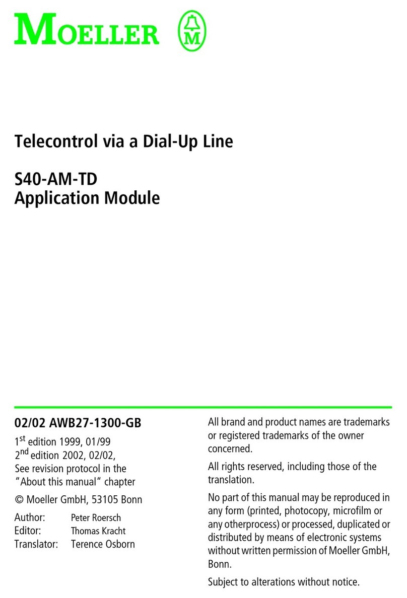
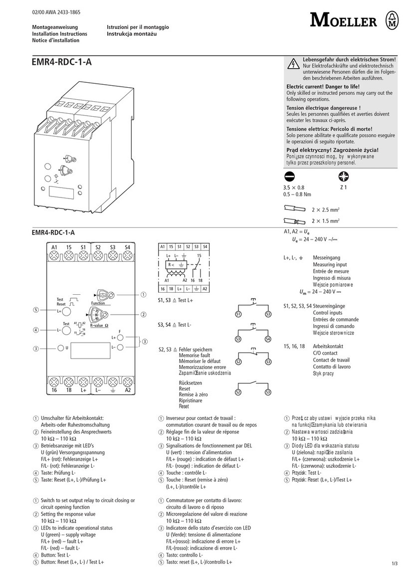
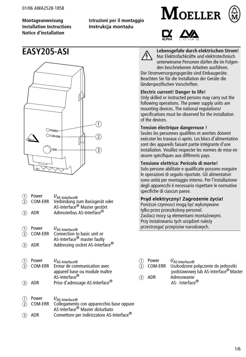
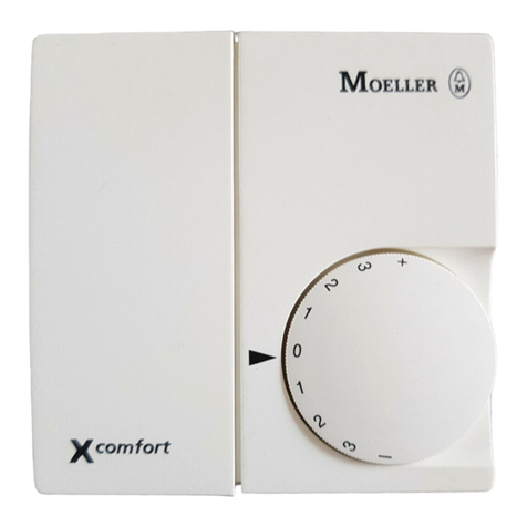
Moeller EMR4-I1-1-A User manual

4 439 842 10 00 0 07/06 AWA2431-2352
Printed in the Fed. Rep. of Germany
EMR4-I1-1-A
EMR4-I15-1-A, EMR4-I15-1-B
(D) Betriebs- und Montageanleitung
Einphasige Stromüberwachungsrelais, EMR4 Reihe
Hinweis: Diese Betriebs- und Montageanleitung enthält
nicht sämtliche Detailinformationen zu allen Typen der
Produktreihe und kann auch nicht jeden Einsatzfall der
Produkte berücksichtigen. Alle Angaben dienen aus-
schließlich der Produktbeschreibung und sind nicht als
zugesicherte Eigenschaften im Rechtssinne aufzufassen.
Weiterführende Informationen und Daten erhalten Sie in
den Katalogen und Datenblättern der Produkte, über die
örtlichen Moeller-Niederlassungen sowie auf der Moeller
Homepage unter http://www.moeller.net. Technische
Änderungen jederzeit vorbehalten. In Zweifelsfällen gilt der
deutsche Text.
Nur von einer entsprechend qualifizierten Fachkraft
zu installieren. Dabei landesspezifische Vorschriften
(z.B. VDE, etc.) beachten. Vor der Installation diese
Betriebs- und Montageanleitung sorgfältig lesen
und beachten. Die Geräte sind wartungsfreie
Einbaugeräte.
(GB) Operating and installation instructions
Single-phase current monitoring relays, EMR4 range
Note: These operating and installation instructions
cannot claim to contain all detailed information of all
types of this product range and can even not consider
every possible application of the products. All statements
serve exclusively to describe the product and have not to
be understood as assured characteristics with legal
force. Further information and data is obtainable from the
catalogues and datasheets of this product, from the local
Moeller sales organisations as well as on the Moeller
homepage http://www.moeller.net. Subject to change
without prior notice. The German text applies in cases of
doubt.
The device must be installed by qualified persons
only and in accordance with the specific national
regulations (e.g., VDE, etc.). Before installing this
unit, read these operating and installation
instructions carefully and completely. The devices
are maintenance-free chassis-mounted units.
(F) Instructions de service et de montage
Contrôleurs de courant monophasé, gamme EMR4
Note: Ces instructions de service et de montage ne
contiennent pas toutes les informations relatives à tous
les types de cette gamme de produits et ne peuvent pas
non plus tenir compte de tous les cas d’application.
Toutes les indications ne sont données qu’à titre de
description du produit et ne constituent aucunes
obligations légales. Pour de plus amples informations,
veuillez-vous référer aux cataloges et aux fiches
techniques des produits, à votre agence Moeller ou à
notre site http://www.moeller.net. Sous réserve de
modifications techniques. En cas de divergences, le texte
allemand fait foi.
L’installation de ces produits doit être réalisée
uniquement par une personne compétente et en
conformité avec les prescriptions nationales
(p.e. VDE, etc.). Avant linstallation de cet appareil
veuillez lire lintégralité de ces instructions.
Ces produits sont des appareils encliquetables
qui ne nécessitent pas d’entretien.
(PL)Instrukcja instalowania i obsługi
Jednofazowe przekaźniki kotroli prądu
serii EMR4
Uwaga:Niniejsza instrukcja nie zawiera wszystkich
szczegółowych informacji każdego typu produktów z tego
typoszeregu i nie uwzględnia wszystkich możliwych zastosowań
tych produktów. Wszytskie stwierdzenia służą wyłącznie do
opisania produktu i nie powinny być rozumiane jako
gwarantowane cechy. Więcej informacji i danych można
uzyskać z katalogów i dokumentacji DTR produktu, z lokalnych
biur sprzedaży firmy Moeller, jak również ze strony internetowej
http://www.moeller.net. Zmiany techniczne zastrzeżone.
W przypadku wątpliwosci stosować tekst w języku niemieckim.
Urządzenia muszą być instalowane tylko przez
przeszkolony personel oraz zgodnie z obowiązującyi
przepisami (np.VDE, etc.). Przed zainstalowaniem tego
urządzenia, przeczytaj dokłądnie i w całosci niniejszą
instrukcję instalowania i obsługi. Urządzenia te są
przeznaczone do montażu na płycie montażowej
i nie wymagają konserwacji.
(I) Istruzioni per l’uso ed il montaggio
Relè di controllo di corrente monofase, serie EMR4
Nota: Le presenti istruzioni per l’uso ed il montaggio non
contengono tutte le informazioni dettagliate su tutta la
gamma di prodotto e non possono trattare tutti i casi
applicativi. Tutte le indicazioni servono esclusivamente a
descrivere il prodotto e non sono da interpretare come
caratteristiche garantite con valore di legge. Per ulteriori
informazioni consultare i cataloghi ed i data sheet dei
prodotti, o la nostra homepage http://www.moeller.net,
oppure rivolgersi alla locale filiale Moeller. Ci riserviamo
di eventuali modifiche tecniche. In caso di differenze o
problemi è valido il testo tedesco.
Installazione solo a cura di personale
specializzato. Bisogna osservare le specifiche
norme nazionali (p.e. VDE, etc.). Prima
dell’installazione leggere attentamente le seguenti
istruzioni. Questi prodotti sono apparecchi ad
incasso, che non hanno bisogno di manutenzione.
(D) Plombierbare Klarsichtabdeckung anbringen
(GB) Fix sealable transparent cover
(F) Fixation du capot transparent condamnable
(PL)Zaplombuj przezroczystą osłonę
(I) Fissare la copertura trasparente sigillabile
(D) Produkt anbringen
(GB) Fix product
(F) Monter le produit
(PL) Zamontuj produkt
(I) Montare il prodotto
(D) Produkt entfernen
(GB) Remove product
(F) Démonter le produit
(PL)Usuń produkt
(I) Rimuovere il prodotto
0,8 Nm
2 x 0,5 ... 4 mm
2
2 x 20 ... 12 AWG
2 x 0,75 ... 2,5 mm
2
2 x 18 ... 14 AWG
ø 4,5 mm / H 1
2 x 0,75 ... 2,5 mm
2
2 x 18 ... 14 AWG
2CDC 252 283 F0005 2CDC 252 282 F0005 2CDC 252 281 F0005
2

4
2
3
1
I
2CDC 252 152 F0006
5
I Frontansicht mit Bedienelementen
Betriebsanzeige mit LEDs
I: LED rot – Anzeige des Messstroms
Schalterstellung R-
VÜberstrom
Schalterstellung Q-
WUnterstrom
R: LED gelb – Anzeige der Schaltstellung des
Ausgangsrelais
Vangezogen
U/T: LED grün – Anzeige Versorgungsspannung und
Zeitablauf
VVersorgungsspannung
liegt an
ZAuslöseverzögerung
TVaktiv
Einstellung der Rückschaltschwelle (Hysterese)
Einstellung des Schwellwertes
Einstellung der Auslöseverzögerung TV(0; 0,1-30 s)
II DIP-Schalter Stellungen
DIP-Schalter zur Einstellung von:
1 ON = Unterstromüberwachung
OFF = Überstromüberwachung
2 keine Funktion
Auslieferungszustand: Alle DIP-Schalter in Position OFF
III DIP-Schalter Position
IV Anschlussdiagramm
1) A1-A2 Versorgungsspannung
2) B1/B2/B3-C Messstrom
3) 11(15)-12(16)/14(18) Ausgangsrelais 1
4) 21(25)-22(26)/24(28) Ausgangsrelais 2
1
2
3
4
5
Deutsch
IV
2CDC 252 272 F0005
II
III
2CDC 252 205 F0005
EMR4-I1-1-A
EMR4-I15-1-A/-B
Messbereich
B1-C 3-30 mA
B2-C 10-100 mA
B3-C 0,1-1 A
B1-C 0,3-1,5 A
B2-C 1-5 A
B3-C 3-15 A1)
1) Bei Messströmen > 10 A ist ein seitlicher Abstand von
10 mm erforderlich
2CDC 252 151 F0006
3

English I Face avant avec dispositifs de
commande
Indication de fonctionnement par LED
I: LED rouge – Etat du courant par rapport au seuil
Position de l’interrupteur R-
Vsurintensité
Position de l’interrupteur Q-
Wsous-intensité
R: LED jaune
– Indication de l’état relais
Vexcité
U/T: LED verte
– Indication tension d’alimentation
et temporisation
VTension d’alimentation
appliquée
ZTemporisation de
déclenchement TVactive
Réglage de l’hystérésis
Réglage de la valeur du seuil
Réglage de la temporisation de déclenchement TV
(0,1-30 s)
II Fonctions des micro-interrupteurs
Micro-interrupteurs pour le réglage de:
1 ON = surveillance de sous-
intensité
OFF = surveillance de
surintensité
2 pas de fonction
Etat de livraison: Tous les micro-interrupteurs en
position OFF
III Position des micro-interrupteurs
IV Schéma de connexion
1) A1-A2 Tension d’alimentation
2) B1/B2/B3-C Courant à surveiller
3) 11(15)-12(16)/14(18) Relais de sortie 1
4) 21(25)-22(26)/24(28) Relais de sortie 2
Français
I Front view with operating controls
Status display with LEDs
I: red LED – Status indication of the measured
current
Switch position R-
Vovercurrent
Switch position Q-
Wundercurrent
R: yellow LED – Status indication of the output relay
Venergized
U/T: green LED –Status indication of supply voltage
and timing
VSupply voltage applied
ZTripping delay TVactive
Adjustment of the release threshold (hysteresis)
Adjustment of the threshold value
Adjustment of the tripping delay TV(0; 0.1-30 s)
II DIP switch functions
DIP switches for the adjustment of:
1 ON = undercurrent monitoring
OFF = overcurrent monitoring
2 no function
State of delivery: All DIP switches in position OFF
III DIP switch position
IV Wiring diagram
1) A1-A2 Supply voltage
2) B1/B2/B3-C Measured current
3) 11(15)-12(16)/14(18) Output relay 1
4) 21(25)-22(26)/24(28) Output relay 2
1
2
3
4
5
EMR4-I1-1-A
EMR4-I15-1-A/-B
Measuring range
B1-C 3-30 mA
B2-C 10-100 mA
B3-C 0.1-1 A
B1-C 0.3-1.5 A
B2-C 1-5 A
B3-C 3-15 A1)
1) In case of measured currents > 10 A, lateral spacing has
to be min. 10 mm
EMR4-I1-1-A
EMR4-I15-1-A/-B
Gamme de mesure
B1-C 3-30 mA
B2-C 10-100 mA
B3-C 0,1-1 A
B1-C 0,3-1,5 A
B2-C 1-5 A
B3-C 3-15 A1)
1) Dans le cas de courants mesurés supérieure à 10 A,
l’espace latérale doit être de 10 mm au minimum
1
2
3
4
5
4

Polski Italiano
I Vista frontale con gli elementi
di comando
LED di visualizzazione dello stato di
funzionamento
I: LED rosso – Indicazione della corrente misurata
Posizione interruttore R-
Vsovracorrente
Posizione interruttore Q-
Wsottocorrente
R: LED giallo
– Indicazione dello stato del relè
d’uscita
Veccitato
U/T: LED verde – Indicazione tensione di alimentazione
e stato della temporizzazione
VTensione di
alimentazione applicata
ZRitardo di intervento TV
attivo
Impostazione della soglia di ripristino (isteresi)
Impostazione del valore di soglia
Impostazione del ritardo di intervento TV(0; 0,1-30 s)
II Funzioni degli interruttori DIP
Interruttori DIP per l’impostazione di:
1 ON = Controllo di sottocorrente
OFF = Controllo di sovracorrente
2 senza funzione
Impostazione di fabbrica: Tutti interruttori DIP in posizione
OFF
III Posizione degli interruttori DIP
IV Schema di collegamento
1) A1-A2 Tensione di alimentazione
2) B1/B2/B3-C Corrente misurata
3) 11(15)-12(16)/14(18) Relè di uscita 1
4) 21(25)-22(26)/24(28) Relè di uscita 2
EMR4-I1-1-A
EMR4-I15-1-A/-B
Campo di misura
B1-C 3-30 mA
B2-C 10-100 mA
B3-C 0,1-1 A
B1-C 0,3-1,5 A
B2-C 1-5 A
B3-C 3-15 A1)
1) Nel caso che la corrente misurata è > 10 A, lo spazio
laterale deve essere min. 10 mm
1
2
3
4
5
IWidok od przodu elementów
sterowania
Wskazania stanu diodami LED
I: LED czerwona Wskazanie mierzonego prądu
Pozycja wskaźnika R-
Vnadprądowy
Pozycja wskaźnika Q-
Wpodprądowy
R: LED żółta Wskazanie zadziałania przekaźnika
wyjsciowego
Vpobudzony
U/T: LED zielona Wskazanie napięcia zasilania
i zwłoki czasowej wyzwlania
VNapięcie zasilania
obecne
ZZwłoka czasowa TV
wyzwalania aktywna
Regulacja progu wyzwalania (histereza)
Regulacja wartosci progowej
Regulacja zwłoki czasowej wyzwlania T V(0; 0.1-30 s)
IIFunkcje przełącznika DIP
Przełącznik DIP dla regulacji:
1 ON=kontrola podprądowa
OFF=kontrola podprądowa
2 bez funkcji
Stan przy dostawie: Wszystkie przełączniki DIP w pozycji OFF
IIIPozycja przełączników DIP
IVSchemat połączeń
1)A1-A2Napięcie zasilania
2)B1/B2/B3-CPrąd mierzony
3)11(15)-12(16)/14(18)Wyjscie przekaźnikowe 1
4)21(25)-22(26)/24(28)Wyjscie przekaźnikowe 2
EMR4-I1-1-A
EMR4-I15-1-A/-B
Zakres pomiarowy
B1-C 3-30 mA
B2-C 10-100 mA
B3-C 0,1-1 A
B1-C 0,3-1,5 A
B2-C 1-5 A
B3-C 3-15 A1)
1) W przypadku pomiaru prądów > 10 A, zachować odległosć
pomiędzy urządzeniami min. 10 mm
1
2
3
4
5
5

Diagramy funkcjonalne
VKontrola nadprądowa
VIKontrola podprądowa
1
2
3
4
5
6
7
8
1
4
3
2
5
6
7
8
9
9
2CDC 252 210 F 0205 - BMA
2CDC 252 211 F 0205 - BMA
7

Arbeitsweise
Die Stromüberwachungsrelais können in einphasigen AC- oder
DC-Netzen je nach Konfiguration zur Über- Roder
Unterstromüberwachung Qeingesetzt werden. Der zu über-
wachende Strom (Messwert) wird dazu an den Klemmen
B1/B2/B3-C eingespeist.
Die Geräte arbeiten nach dem Arbeitsstromprinzip.
Über- bzw. unterschreitet der Messwert den eingestellten
Schwellwert, ziehen die Ausgangsrelais nach der eingestellten
Auslöseverzögerung TVan. Unter- bzw. überschreitet der
Messwert den Schwellwert minus bzw. plus die eingestellte
Hysterese, fallen die Ausgangsrelais in ihre Ruhestellung zurück.
Die Hysterese ist in einem Bereich von 3-30 % des Schwellwerts
einstellbar.
Funktionsdiagramme
V Überstromüberwachung
VI Unterstromüberwachung
햲Versorgungsspannung A1-A2
햳Schwellwert
햴Hysterese
햵Messwert
햶Ausgangsrelais 1
햷LED grün
햸LED rot
햹LED gelb
햺Ausgangsrelais 2
Deutsch
9

English Français
Operating principle
Depending on the configuration, the current monitoring relays
can be used for over- Ror undercurrent monitoring Qin
single-phase AC or DC systems. The current to be monitored
(measured value) is applied to terminals B1/B2/B3-C. The
devices work according the open-circuit principle.
If the measured value exceeds resp. drops below the adjusted
threshold value, the output relays energize after the set tripping
delay TV.
If the measured value exceeds resp. drops below the threshold
value plus resp. minus the adjusted hysteresis, the output relays
de-energize.
The hysteresis is adjustable within a range of 3-30 % of the
threshold value.
Function diagrams
V Overcurrent monitoring
VI Undercurrent monitoring
햲Supply voltage A1-A2
햳Threshold value
햴Hysteresis
햵Measured value
햶Output relay 1
햷green LED
햸red LED
햹yellow LED
햺Output relay 2
Principe de fonctionnement
Selon la configuration, les contrôleurs de courant peuvent être
utilisés pour surveiller une sur- Rou sous-intensité Qdans
des réseaux monophasés AC ou DC. Le courant à surveiller
(valeur mesurée) est appliqué aux bornes B1/B2/B3-C. Les
relais fonctionnent en logique positive.
Si la valeur mesurée dépasse ou chute en dessous de la valeur
de seuil ajustée, les relais de sortie s’excitent avec la
temporisation de déclenchement TVajustée.
Les relais de sortie retombent, si la valeur mesurée dépasse ou
chute en dessous de la valeur de seuil plus ou moins
l’hystérésis ajustée.
L’hystérésis est ajustable dans une gamme de 3-30 % de la
valeur du seuil.
Diagrammes de fonctionnement
V Surveillance de surintensité
VI Surveillance de sous-intensité
햲Tension d’alimentation A1-A2
햳Valeur du seuil
햴Hystérésis
햵Valeur mesurée
햶Relais de sortie 1
햷LED verte
햸LED rouge
햹LED jaune
햺Relais de sortie 2
10

Polski Italiano
Funzionamento
Dipendentemente dalla configurazione, i relè di controllo di
corrente possono essere utilizzati per controllare sovra- Ro
sottocorrenteQin sistemi CA/CC monofasi. La corrente da
controllare (valore misurato) viene applicata ai morsetti B1/B2/
B3-C. Gli apparecchi lavarono a secondo del principio di
funzionamento normalmente aperto.
Se il valore misurato aumenta o diminuisce oltre il valore di soglia
impostato, i relè di uscita si eccitano con il ritardo di intervento TV
impostato.
Se il valore misurato diminuisce o aumenta oltre il valore di soglia
meno o più l’isteresi impostata, i relè si diseccitano nuovamente.
L’isteresi è regolabile nel range da 3-30 % del valore di soglia.
Diagrammi di funzionamento
VControllo di sovracorrente
VIControllo di sottocorrente
햲Tensione di alimentazione A1-A2
햳Valore di soglia
햴Isteresi
햵Valore misurato
햶Relè di uscita 1
햷LED verde
햸LED rosso
햹LED giallo
햺Relè di uscita 2
Zasada działania
W zależnosci od konfiguracji, przekaźniki kontroli prądu mogą
być użyte do monitorowania wartosci nadprądowej lub podprądowej
w jednofazowych sieciach AC lub DC. Monitorowany prąd
(wartosc pomierzona) jest doprowadzany do zacisków B1/B2/
B3-C. Urządzenia działają wg zasady otwartego obwodu.
Jeżeli wartosc mierzona przekracza względnie spada poniżej nastawionej
wartosci progowej, to po czasie zwłoki wyzwalania Tvpobudzone zostają
przekaźniki wyjsciowe.
Jeżeli pomierzona wartosc przekracza względnie spada poniżej wartosci
progowej plus/minus nastawiona histereza, to przekażniki wyjsciowe
zostają odwzbudzone.
Histereza jest regulowana w zakresie 3 - 30% wartosci progowej.
Diagramy funkcjonalne
VKontrola nadprądowa
VI Kontrola podprądowa
햲Napięcie zasilania A1-A2
햳Wartosć progowa
햴Histereza
햵Wartosć pomierzona
햶Przekaźnik wyjsciowy 1
햷LED zielona
햸LED czerwona
햹LED żółta
햺Przekaźnik wyjsciowy 2
11
This manual suits for next models
2
Table of contents
Other Moeller Control Unit manuals

Moeller
Moeller DILM32-XTE Series User manual

Moeller
Moeller S40-AM-TD User manual

Moeller
Moeller NZM3-XD User manual

Moeller
Moeller EMR4-RDC-1-A User manual

Moeller
Moeller XIOC AWB2725-1452GB User manual

Moeller
Moeller Xcomfort CAEE-02/01 User manual

Moeller
Moeller RA-MO Series User manual

Moeller
Moeller XC-CPU101 Series Guide

Moeller
Moeller WINbloc eco PROFIBUS-DP Series User manual

Moeller
Moeller Room-Manager User manual