Benchmark MyTemp Mini CO2 User manual
Operations Manual

Page 2/ 12
NO.
CONTENTS
PAGE
1
GENERAL INFORMATION ON PRECAUTION
3
2
CONFIGURATION
5
3
FEATURES AND SPECIFICATIONS
7
4
INSTALLATION
8
5
OPERATION
9
6
SERVICE AND CONTACT
12
Page 3/ 12
1. General Information and Precautions
Safety Symbols:
1.1. Precautions related to the power cable
Always leave at least 3cm between the power cable and the back wall to ensure that the power cable
is not pressed to firmly against the power inlet.
Always use the power supply and plug that was supplied with this product.
Never make contact with the power code with wet hands. (This can result in electric shock.)
Never use a damaged power cord or outlet.
In the event of smoke or a burning smell, immediately remove the power cord from the outlet.
1.3. Precaution for use
Do not attempt to disassemble this product. If service is required, please contact your local
representative.
Never operate a flammable spray near the product. (This can result in a fire hazard.)
Always use caution when using flammable substances such as benzene, alcohol
and LP gas. ( Failure to do so can result in a fire hazard.)
Make sure to prevent foreign substances from getting into the sealing silicon of the door. (The
inflow of outside air can cause the change of temperature in chamber and discoloration of the
packing part by a foreign substance.)
Permissible ambient temperature range for transport: -10℃to 60℃.
Page 4/ 12
Please check the voltage & Hertz written on serial label.
(Over-voltage, under-voltage can damage the product and poor performance.)
When you install the product, you have to put the distance of at least
30cm from the wall. To completely separate the unit from the power supply, power plug
must be disconnected. Install the unit in the way that the power plug is easily accessible
and can be easily pulled in case of danger.
Install the unit at a flat surface, free from vibration and in a well-ventilated location.
(If the ground is not flat, it can cause an excessive vibration of the product.)
Excessive CO2 is harmful to human when in high concentrations.
Any excess amount of CO2 has to be led out via ventilation or by connection to a suitable
exhaust system.
Page 5/ 12
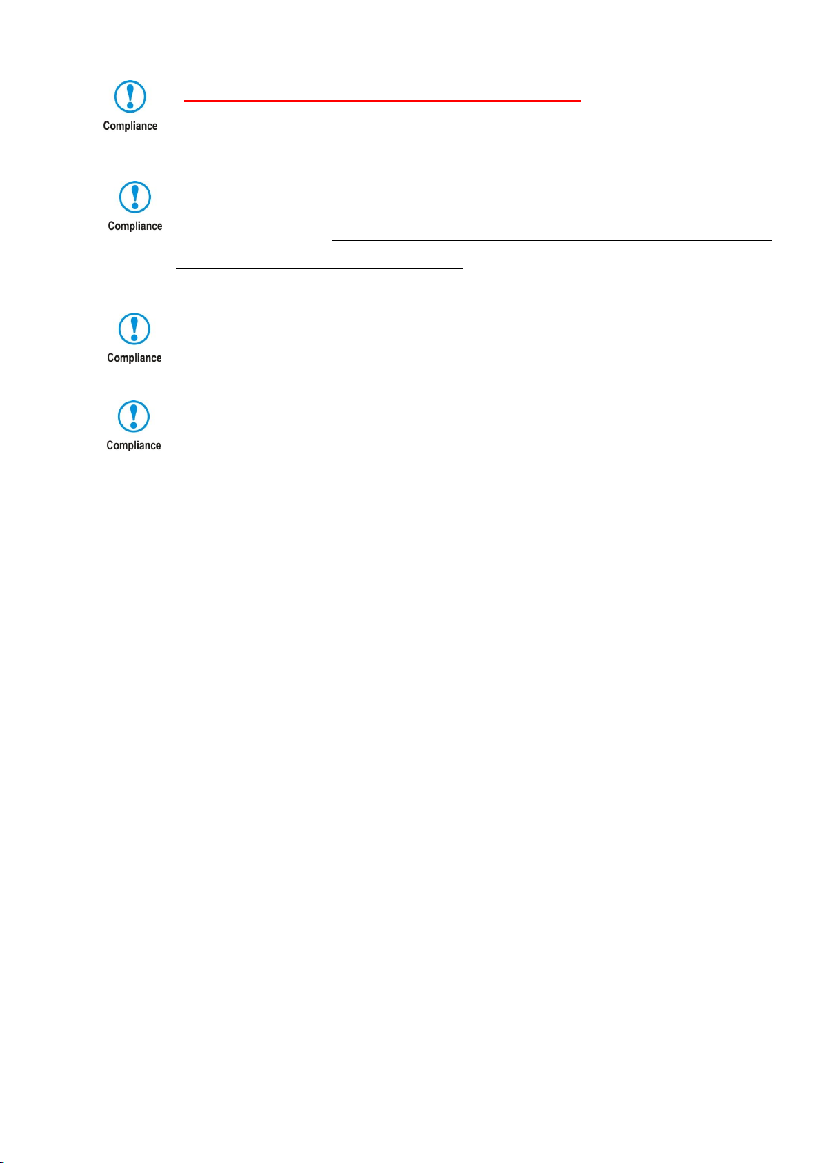
2. Configuration. Figure 1. Front side
Handle for transport
Control panel
Door Handle
Figure 2. Inner Chamber
Duct for Air flow
Stainless
Steel shelf
Air Circulation Fan
Water Container
for Humidity
Support, for closing the door
I
IR CO₂sensor

Page 6/ 12
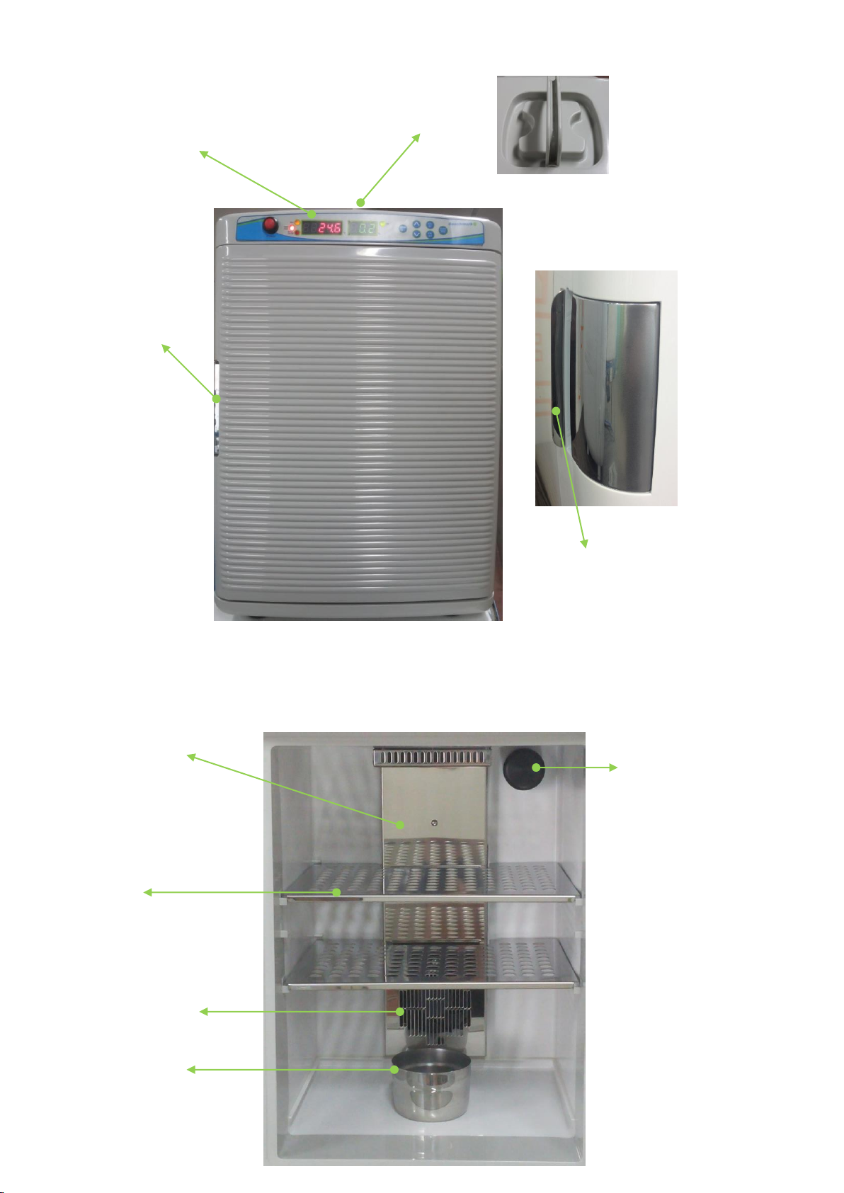
Figure 3. Back of Incubator
CO₂Sample Port
Serial Label
CO₂Inlet Port
Non-Slip Rubber Feet
Do not confuse CO₂Inlet Port and Sample Port. Tube from gas cylinder must be connected to CO
₂Inlet Port. Sample Port is used to check the CO₂density with an external analyzer.
Figure 4. Control Panel
2 3 11
1 4 5 6 7 8 9 10 12
1. Main Power Key
2. HOT/COOL LED Indicator : RED(heating) BLUE(Peltier –cooling)
3. RUN LED Indicator: Normal –Slow flashing Failed –Fast flashing
4. Alarm LED Indicator : RED –Alarm Off No Light –Alarm On
5. Temperature display
6. CO₂Display
7. CO₂Injecting Indicator
8. Temperature Set Key
9. Up & Down Key (for setting the temperature and CO2 percentage)
10. Calibration Mode Key
11. CO₂Set Key
12. ALARM/MUTE Key: Press and hold for 3 seconds to switch Alarm on or off. (Press quickly
to temporarily deactivate the alarm)
DC12V
Power Inlet
Ventilation Fan

Page 7/ 12
3. Features and Specifications
3.1. Features
1. Light weight, compact and portable.
2. Precise temperature control by Peltier. (ambient -10’C, lowest temp. is 15’C at 25’C RT)
3. Advanced air circulation for improved uniformity
4. Natural Humidification System with included water tray
5. 12V vehicle adapter for use in cars or boats
3.2. Specifications
Item
Specification
Chamber volume
20L
Temperature range
15℃~ 60ºC at ambient 25ºC
Temperature uniformity
±0.25℃(at 37ºC)
Temperature
accuracy(display)
±1℃
CO2 range
0~20%
CO2 sensor
Dual beam IR sensor
CO2 accuracy
±0.1% (at 5%)
Humidity
70 to 80%
Gas inlet pressure
1 bar
Display
LED display
Cooling & Heating
By peltier elements
Shelf
2 each, stainless steel
In & Outside material
Interior
10.3 x 9.3 x 12.8 in. / 26 x 23.5 x 32.5 cm
Exterior
13.2 x 14.5 x 18.7 in. / 33.5 x 37 x 47.5 cm
Weight
8.5kg
Power
DC12V/5A, AC100 ~ 240V, 50Hz~60Hz
Power consumption
Hot : 75W / Cool : 75W

Page 8/ 12
4. Installation
Before beginning the installation, always:
Inspect the packaging for damage –When the instrument is received, inspect the item carefully to check
any transit damage. In the event of damage, always report the damage to the shipping carrier and your
local representative immediately.
Included in the package:
1. Stainless Steel Perforated shelf –2 Pcs
2. Power Cord –1 Pcs
3. Main Power Adapter 12V DC(100 ~ 230V, 50 ~60Hz) –1Pcs
4. 12V DC Car Jack –1 Pcs
5. Stainless Steel Water Container for humidity- 1P
6. CO₂Gas Tubing with in-line CO₂Gas filter –1Pcs
7. Operating Manual- 1Pcs
Above parts are packed inside incubator. When received, open the door of incubator and remove all
parts to check confirm receipt.
Cleaning before use
Before conducting cell culture in this mini incubator, It is recommended to clean up entire chamber and
shelves and water container by using soft cloth with at least 70% Ethanol mixed of 30% distilled water.
Do not make hot air or H₂O₂or UV decontamination in this plastic housing incubator.
Installation Procedure:
1. Place the incubator at the desired location.
Always avoid placing the incubator in:
- An area near equipment generating heat or cold air to incubator.
- Direct sunlight
- An uneven surface or table.
- A place with heavy vibration
- A place with little air ventilation space behind the incubator.
2. Place the shelves and water container as shown in chapter “CONFIGURATION”. If desired, place
the stainless steel water container at bottom of chamber toward the back of incubator (in order to get it
to be close to circulation fan). This increases the humidity.
Distilled water is recommended in order to avoid contamination and corrosion.
If possible, use warm (~37℃) distilled water for immediate humidification.

Page 9/ 12
3. Connect the CO₂Gas supply
The Gas tubes provided are combined with 4mm (dia.) and 6mm (dia.) tube. Insert the 4mm edge of tube
to gas inlet port and connect 6mm edge of tube to gas regulator which is installed on the cylinder or gas
line in your lab.
DO NOT connect the gas supply to CO₂“SAMPLE PORT”
-Turn on the gas supply with the pressure set to 1 Bar (or 14.5 Psi)
NOTE! : To confirm that there are no leaks in the CO₂connections, a “bubble check”is recommended.
Apply soapy water to each fitting and check if any bubbles are generated. If so, readjust the fitting.
4. Connect the power cord.
-This incubator is provided with 12V DC adopter which is available at the range of voltage from 100 to
240V.
-Plug the connector to power receptacle and back of incubator (refer to CONFIGURATION)
-Plug the power plug to the outlet.
5. Operation
5.1 Power switch on
Turn on the power switch. The digital LED will display current temperature and CO₂% in the chamber.
5.2 Setting temperature
a. Press the "TEMP SET" key, then, the LED screen will flash and display current programmed
temperature.
b. Set up the desired temperature by pressing UP (▲) or DOWN (▼).
c. Press "TEMP/SET" key after adjustment. The “SAVE” message is shown on the display.
Note: If you don't press "SET" key after set-up, the new set-up value will not be saved.
5.3 Setting CO2
a. Press "CO2 SET" key. Then, LED screen will be flashing.
b. Input the desired value of Co2 density by adjusting UP (▲) or DOWN (▼) key
c. Press "SET" key again after input. “SAVE” is shown up on LED screen as below.
Note: If you don't press "CO2 SET" key after set-up, the new set-up value will not be saved.

Page 10 / 12
5.4 Calibration for temperature and CO2
In the event that recalibration is required for the temperature or CO2 percentage, please follow
the procedure below:
Measure CO₂density and Temperature after incubator is stabilized (after 2 hours of having
reached the desired settings)
a. Press and hold “CAL”key for 10 seconds. Then, LED will be flickering as below.
Channel one refers to the temperature calibration. To adjust:
Press UP (▲) to increase the setting by as much as the difference between the measured value and
the displayed value.
Press DOWN (▼) to decrease the setting by as much as the difference between the measured value
and the displayed value.
Ex.) If measured temperature is 38℃and display shows 37℃- Then press up 1℃.
Note
* Calibration range for temperature is ±5℃
* To go to next channel, press “CAL/SET”button. After 5th channel, the LED is back to the
temperature display.
Channel 2 does not refer to an adjustable function. Please skip this channel by
pressing the set button once.
Channel 3 does not refer to an adjustable function. Please skip this channel by
pressing the set button once.
Page 11 / 12
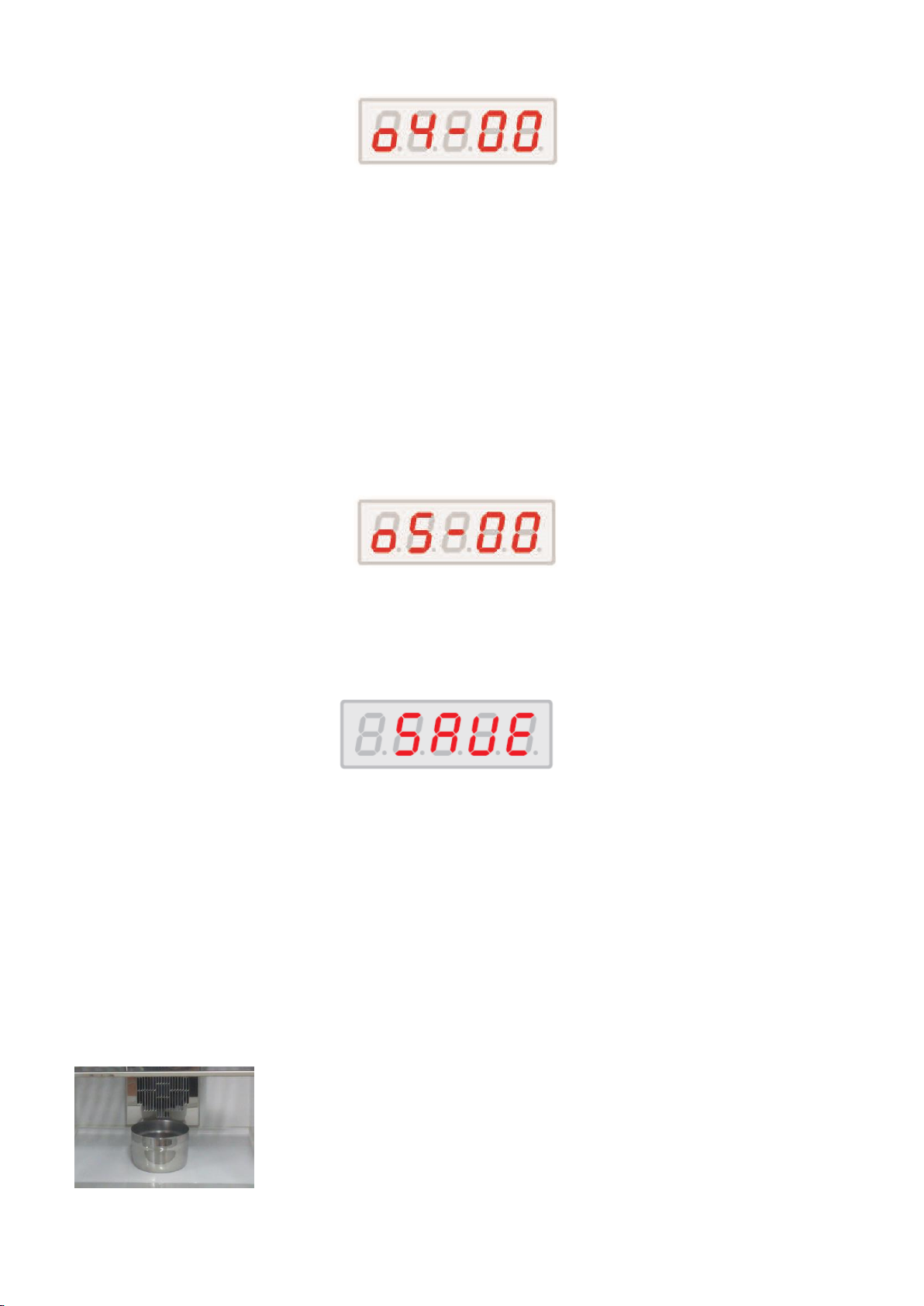
d. The fourth channel is the “CAL SET”
☞
CO2 density calibration
Channel 4 is at CO2 density calibration stage.
Press UP (▲) to increase the setting by as much as the difference between the measured value and
the displayed value.
Press DOWN (▼) to decrease the setting by as much as the difference between the measured value
and the displayed value.
Ex) If measured CO2 value is 5% and Display shows 4%, then press up 1%.
e. Channel 5 does not refer to an adjustable function.
Please skip this channel by pressing the set button once.
f. Channel 6 does not refer to an adjustable function.
Please skip this channel by pressing the set button once.
When all 6 channels have been passed, press the SAVE button to save all adjusted values.
5.5. Humidity
Mini CO2 incubator adopts natural humidity system using a water tray/container.
For adding humidity, fill with distilled water up to the water line. With the door closed, this should result
in a proper humidity level (at about 80%) during operation of incubator.
Place the water container close to back of chamber so the container is more exposed to heated air from
the fans and element.
NOTE: It is not recommended to transport the incubator without emptying the water container first.
In case that humidity is necessary during transportation, ensure the water
container to be securely held at bottom of chamber (e, with tape).

Page 12 / 12
5.6 Alarms
Alarm System On or Off
1. Turn on alarm system by pressing alarm button for about 5 seconds. When switching alarm on or
off, a short audible alarm will come out for notice and the pilot lamp of Alarm will either flash or not.
When alarm system is armed, alarm pilot lamp is no lighting. When Alarm system is disarmed, LED
LAMP of alarm is lighting to indicate to user to be noted.
2. When the alarm system is switched on, or after any values have been reprogrammed, the Alarm
system is inactive until the set pointvalues (±1) are achieved and maintained for more than 3 minutes,
after which the Alarm System is armed. This is to activate alarm after stabilization of temp and CO₂
percentage.
Alarm
If an alarm occurs, a beep will be heard and a fast flashing will occur on the RUN lamp indicator.
- If temperature deviates more than ±1℃ from set point for more than 8 min. the alarm will occur.
-Pressing mute button once will temporarily deactivate (10 minute delay). If temperature is not
recovered in this delay time, alarm occurs again.
-Alarm will automatically stop once temperature is recovered into tolerance range (±1℃)
-If CO₂deviate more than ± 1% from set point for 8 min., the alarm will occur.
-Alarm will automatically stop once temperature is recovered into tolerance range.
-Pressing mute button once will temporarily deactivate (10 minute delay). If temperature is not
recovered in this delay time, alarm occurs again.
If the door is left open for +30 seconds, the alarm will occur.
- If door closed during alarming, alarm will stop immediately.
- Pressing mute button when door open will temporarily delay the alarm for 3 minutes.
6. Service and Contact
Service on the instrument should only be performed by qualified service personnel. To request service
or technical support, please contact Benchmark Scientific or your local Benchmark Scientific
representative.
Ph: +1-908-769-5555
Fax: +1-732-313-7007
Em: Info@BenchmarkScientific.com
Web: www.BenchmarkScientific.com
P.O. Box 709 Edison, NJ 08817, USA
Table of contents
Other Benchmark Accessories manuals


