Benchmark BAKER ATLAS 5715XA User manual

AMS4A040 PANEL USER MANUAL Rev H Nov 2006 Page 1 of 39
OPERATIONS AND MAINTENANCE MANUAL
WINCH OPERATORS PANEL
BAKER ATLAS 5715XA PANEL
F140529000
Kerr p/n AMS4A040
TABLE OF CONTENTS
SECTION DESCRIPTION
1.0 GENERAL DESCRIPTION
2.0 DETAILED DESCRIPTION OF FEATURES
3.0 MENUOPERATINGINSTRUCTIONS
OPENHOLEMODE
4.0 MENUOPERATINGINSTRUCTIONS
CASED HOLE MODE
5.0 SYSTEM OPERATING INSTRUCTIONS
6.0 DRAWINGS, SETUP PROCEDURES AND
PARTS LISTS
7.0 INSTALLINGNEWSOFTWARE
8.0 CABLE DRAWINGS
9.0 CETESTCERTIFICATES
AMS4A040 PANEL USER MANUAL Rev H Nov 2006 Page 2 of 39
1.0 INTRODUCTION
1.1 GENERAL DESCRIPTION
This panel is designed to acquire and display depth, tension, and magnetic
mark data from a wireline logging winch unit. The panel provides the
operator a means to set and make adjustments to the data as necessary.
Depth is displayed from data provided from an encoder mounted on a
measuring device. The encoder quadrature pulses are passed through to
the acquisition system. The tension data is provided by a load pin and is
also passed through to the acquisition system.
The panel can be set in either open hole logging or cased hole logging
modes. This is done by installing jumper J3 on the main processor board
for cased hole mode or removing the jumper for open hole mode.

AMS4A040 PANEL USER MANUAL Rev H Nov 2006 Page 3 of 39
1.2 FEATURES AND SPECIFICATIONS
-- Digital displays for depth, line speed, tension and magnetic marks (or CCL offset)
-- Analog incremental tension meter, 4 inch (108 mm) dia., 270 degree
-- Differential or Incremental tension zero push button switch
-- Excessive tension alarm setting allows operator to set tension alarm to a
predetermined value. Contact closure is provided for winch shutdown
-- Zero Depth button - sets depth to 0. Depressing button again resets depth to
previous setting. Only works when line speed is zero
-- Approaching surface alarm
-- Depth adjust up or down switches. Only works when winch is stopped
-- Load cell zero & calibrate controls. Only works when there is no load on cable
-- Depth & tension saved in non-volatile memory at power loss
-- Outputs for Magnetic Marks, Tension and Encoder to interface to an acquisition
system.
-- RS485 Interface for additional control and data outputs.
-- Can be set to display either English or Metric units.

AMS4A040 PANEL USER MANUAL Rev H Nov 2006 Page 4 of 39
2.0 DETAILED DESCRIPTION OF FEATURES
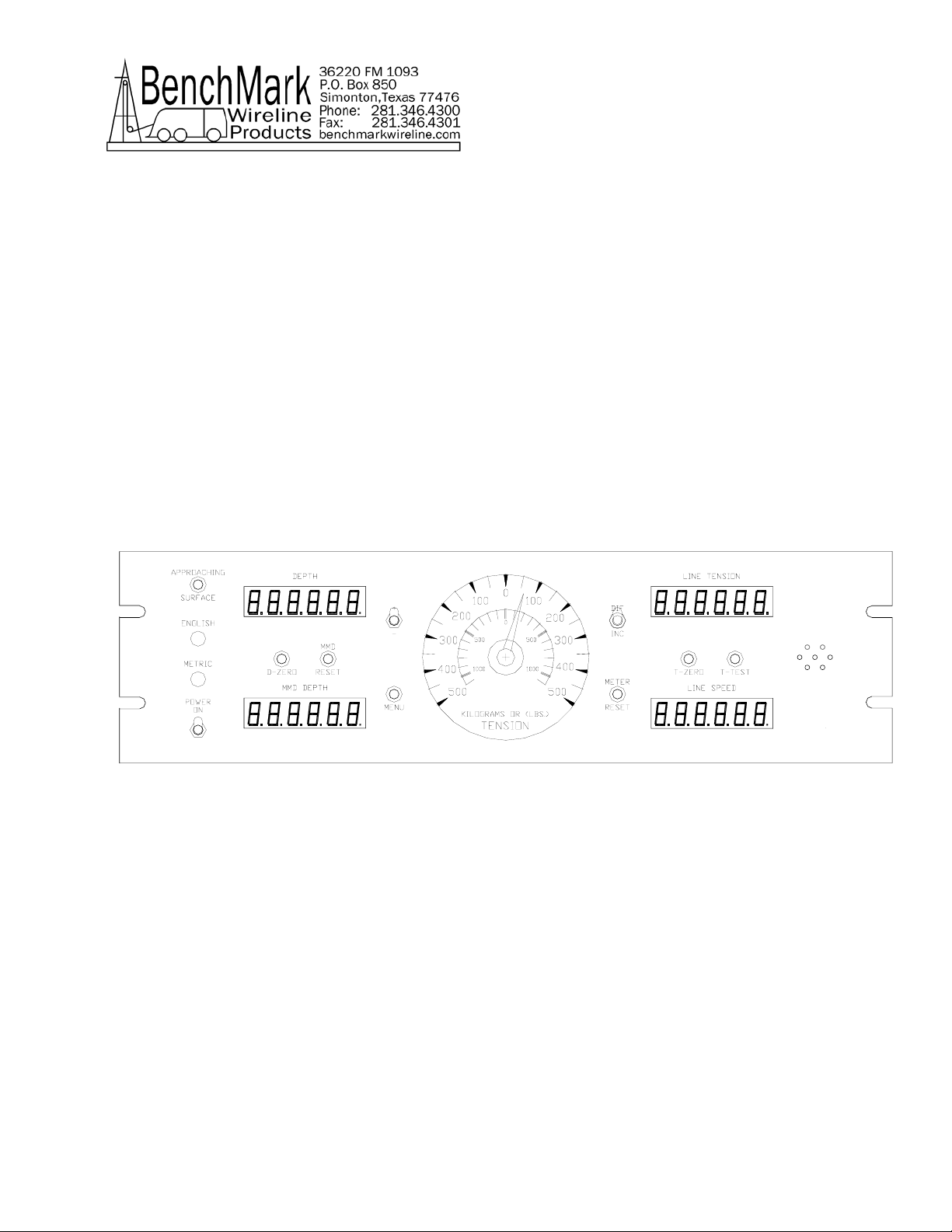
2.1 FRONT PANEL
2.1.1 ANALOG TENSION METER
This meter displays either differential or incremental tension. This
provides a more visual display of tension change.
2.1.2 INCREMENTAL/TOTAL TENSION SWITCH
This switch will change the analog meter from Incremental tension to
Differential tension.
Incremental tension provides a high resolution tension scale. It must
be periodically reset as tension increases or decreases to keep it
from pegging out.
Differential tension provides a delta tension reading. The meter will
slowly reset itself to 0 so the reset switch is not necessary.
2.1.3 METER RESET SWITCH
This switch will reset the meter to the 0 (center) position.
2.1.4 DEPTH DISPLAY
This meter provides a digital display of depth.
2.1.5 LINE TENSION DISPLAY
This meter provides a digital display of total line tension.
2.1.6 LINE SPEED DISPLAY
This meter provides a digital display of line speed.
2.1.7 MAGNETIC MARK DISPLAY
This meter provides a digital display of the depth where the last
mark was detected. It is also used as a CCL offset display when the
panel is configured for cased hole operations (MODE 3).

AMS4A040 PANEL USER MANUAL Rev H Nov 2006 Page 5 of 39
2.1.8 MAGNETIC MARK RESET
Pressing the MMD reset button clears the last mark setting. The
next mark detected will be used to set the window for any
subsequent marks.
2.1.9 ZERO DEPTH
Pressing this button will reset the depth to 0. Depressing the button
again will reset the depth to the previous setting. The Zero Depth
button will only work when the line speed is zero (i.e. winch not
moving).
2.1.10 MENU
Pressing this button will activate the menu software. The software
feature to be set will be displayed on the DEPTH display. The
features can be toggled through by pressing the menu button until
the desired feature is displayed.
2.1.11 + / - SWITCH
This switch is used for different functions. It is used to change the
depth setting in either an up or down direction. The winch must be
stopped before the depth can be set. In menu mode (see section
3.0) the switch is used to set menu parameters.
2.1.12 APPROACHING SURFACE LED AND ALARM
This LED is lit and an audible alarm is sounded when the depth is
less than 100' (30 m). This is a warning to the hoist operator that
they are approaching surface and should take care to get the
equipment safely out of the well. When the LED is depressed, the
alarm will stop but the LED will continue to blink. Once the depth
reading is greater than 100' (30 m), both the alarm and the LED will
turn off.
2.1.13 ENGLISH / METRIC UNITS
These LEDs will indicate if the panel is in English or metric mode. If
the depth is set to English, the English LED will be lit. If the depth is
set to Metric the Metric LED will be lit. The tension can be set to
English (LBS) or Metric (KG) but it will not light the LED.

AMS4A040 PANEL USER MANUAL Rev H Nov 2006 Page 6 of 39
2.1.14 T-ZERO SWITCH
Use this switch to set the tension to 0 at the start of a logging run.
This will zero out the tension circuit. The line should be slack
through the head at this time.
2.1.15 T-TEST SWITCH
Press T-TEST and verify that the panel tension reads 20000 lbs
(MODE 5) or 5000 lbs (MODE 3). Verify tension is being properly
recorded on acquisition system.
2.2 REAR PANEL
2.2.1 12 – 24 VDC
This connector supplies dc power for the panel operation (9 VDC
min, 30 VDC max). The panel can operate on either 12 or 24 vdc
(12 vdc is U.S. truck standard voltage, 24vdc is European truck
standard voltage). Pin A is positive, pin B is negative.
2.2.2 OVER TENSION CONTACT
This connector provides a connection to the overtension circuit
relay. When an overtension condition is active, the two pins are
connected together. In normal position the two pins are open. This
feature can be used to interface to the winch unit control system to
provide automatic hoist shutdown at an overtension condition.
2.2.3 SIGNAL INPUT
Encoder, tension, and magnetic mark signals and power are passed
through this connector to/from the sensors on the measuring head.
2.2.4 SIGNAL OUTPUT
Encoder, tension, and magnetic mark signals, processed and some
unprocessed are passed through this connector to the acquisition
system.
2.2.3 RS485 SERIAL INTERFACE
This connector provides an RS485 interface from the panel to the
acquisition system. Connectors are provided for both RS485 in and
out.
AMS4A040 PANEL USER MANUAL Rev H Nov 2006 Page 7 of 39
2.3 JUMPER SETTINGS
A row of jumpers are located on the internal processor board to set the
panel in different configurations.
J1 on = DEPTH IN METERS
J1 off = DEPTH IN FEET
J2 on = TENSION IN KG
J2 off = TENSION IN POUNDS
J3 on = CASED HOLE MODE (AM3K + CASE OR HOIST)
J3 off = OPEN HOLE MODE (AM5K + FOCUS)
J4 off = Rev D or earlier PC board
J4 on = Rev E PC board
J5 on = FOCUS mode
J5 off = AM5K standalone mode
J1 and J2 are only in affect when J5 is off
2.3.3 PROCESSOR REBOOT
In the event of a panel "lock up" or other malfunction, the processor
in the panel can be rebooted by turning off the panel, depressing the
T-ZERO and T-TEST buttons simultaneously then turn the power
back on while the buttons are depressed.
When the panel is rebooted, all the menu settings will be returned to
the factory default settings.

AMS4A040 PANEL USER MANUAL Rev H Nov 2006 Page 8 of 39
3.0 MENU COMMANDS – OPEN HOLE MODE
This panel has internal software which allows it to be set for various
configurations. To change the settings, press the MENU button. The feature to be
set will be displayed on the DEPTH display. Press the MENU button again until
the feature you want to set is displayed.
In this mode (open hole) the panel is configured to work with the AM5K measuring
head and the Baker Atlas FOCUS acquisition system.
Jumper J3 must be removed to put the system in this mode (refer to section 2.3).
The parameters for each feature will be displayed on the LINE TENSION display.
Press the +/- switch to cycle through all the available parameters. When the
value you want to select is displayed, press the MENU button. ACCEPT will then
be displayed. Press + for yes, - for no.
Following is a listing of all the available settings.
3.1 CABLE SIZE
Functionality:Cable size selection automatically sets load pin angle setting
for the selected cable size.
If other is selected, the LCA value needs to be entered. This
value is based on the bend angle of the cable over the
tension wheel. This value is empirically derived and must be
furnished by the measuring head manufacturer (Kerr
Measurement Systems Inc.). Contact Kerr with the line
specifications.
Procedure: Use +/- switch to select cable size.
Indication: CABLE will be displayed on the DEPTH display and the
selections will be displayed on the LINE TENSION display.
Cable Size Values available
7-32
9-32
5-16
3-8
7-16
15-32
SLAM

AMS4A040 PANEL USER MANUAL Rev H Nov 2006 Page 9 of 39
S-SLAM
Other
Default value is 7-16
If OTHER is selected, two additional options are available.
LCA and WHLCIR.
LCA (Load Cell Angle). This setting allows for the use of a
sheave mounted load cell. The angle of the cable exiting the
sheave should be entered. Typically for a load cell mounted
above the top sheave the LCA would be 0. For a load cell
mounted to the bottom sheave the LCA would be 90 (90
degrees). Default value is 0.
WHLCIR (Wheel Circumference). This value is set to the
circumference of the measuring wheel to ensure the depth is
measured correctly. Default value is 2.0 ft.
3.2 TEN ALARM
Functionality:When preset tension value is reached, alarm sounds and
tension display flashes value
Procedure: Use +/- switch to set the tension alarm setting.
Indication: TALARM will be displayed on the DEPTH display and the
value will be displayed on the TENSION display as it is being
set.
Selection: Each cable size will have a corresponding Tension Alarm
setting. Only the setting for the cable size selected (see
menu option 1) can be adjusted.
Default Values
7-32 1500
9-32 2400
5-16 2400
3-8 2400
7-16 2400
15-32 2400
SLAM 2400
S-SLAM 2400

AMS4A040 PANEL USER MANUAL Rev H Nov 2006 Page 10 of 39
3.3 TENSION SHUTDOWN
Functionality:When value is reached, alarm sounds, tension display flashes
value, and tension contact closure switch is closed. This can
be used to provide a signal to automatically stop the winch.
Procedure: Use +/- switch to set tension shutdown setting
Indication: TSHTDN will be displayed on the DEPTH display and the
value will be displayed on the TENSION display as it is being
set.
Selection: Each cable size will have a corresponding Tension Alarm
setting. Only the setting for the cable size selected can be
adjusted.
Default Values
7-32 2000
9-32 3000
5-16 3500
3-8 3500
7-16 3500
15-32 3500
SLAM 3500
S-SLAM 3500
Note: The RESET or Approaching Surface button needs to be
depressed before the winch shutdown relay will de-energize.
3.4 DELTA TENSION ALARM
Functionality:When the delta tension setting is reached the alarm sounds.
In incremental mode, you must periodically press meter reset
or this alarm will sound when the tension reaches the set
value. In differential mode, the meter will reset itself and the
alarm will only sound on a quick change of tension.
Procedure: Use +/- switch to set the Delta Tension setting.
Indication: DT-TEN will be displayed on the DEPTH display and the
value being set will be displayed on the TENSION display as
it is being adjusted.

AMS4A040 PANEL USER MANUAL Rev H Nov 2006 Page 11 of 39
3.5 DELTA TENSION SHUTDOWN
Functionality:When value is reached, alarm sounds, tension display flashes
value, and tension contact closure switch is closed. This can
be used to provide a signal to automatically stop the winch.
Procedure: Use +/- switch to set tension shutdown setting
Indication: DTSHDN will be displayed on the DEPTH display and the
value will be displayed on the TENSION display as it is being
set.
Note: This parameter is derived from the reading on the analog
meter. If the DTSHDN value is set to 500 then whenever the
tension reading on the meter is greater than 500 the winch
shutdown relay will be activated.
Note: The RESET or Approaching Surface button needs to be
depressed before the winch shutdown relay will de-energize.
3.6 DEPTH ADJUST (Shim)
Functionality:The shim amount selected will automatically be added or
subtracted from the depth input.
Procedure: Use +/- switch to set the shim setting.
Indication: DP-ADJ will be displayed on the DEPTH display and the
value will be displayed on the TENSION display as it is being
set. The values are feet / thousand.
Default value is 0.
3.7 DEPTH ALARM
Functionality:When Alarm depth value is reached, the alarm will sound and
LED will flash. Pressing the LED will turn off alarm but the
light will continue to flash.
Procedure: Use +/- switch to set the depth alarm value.
Indication: DALARM will be displayed on the DEPTH display and the
value will be displayed on the TENSION display as it is being
set.
Default value is 100’

AMS4A040 PANEL USER MANUAL Rev H Nov 2006 Page 12 of 39
3.8 MMD
Functionality:The MMD window determines when the next mark can be
detected. The cable must travel at least the distance of the
value set before a mark can be detected. Marks can only be
detected if they occur within this window. I.E. If the window
is set for 95', the cable must travel 95' from the last mark
before a new mark can be detected.
Procedure: Use +/- switch to change MMD window value.
Indication: MMD will be displayed on the DEPTH display and the window
value will be displayed on the TENSION display as it is being
set.
Pressing the MMD reset button clears the last mark setting.
Default value is 5’
3.9 MMD DETECT
Functionality:If STRONG is selected, only marks greater than 4 gauss will
be detected. If ALL is detected, any mark stronger than .3
gauss will be detected.
Procedure: Use +/- switch to toggle MMD detect value from STRONG to
ALL.
Indication: DETECT will be displayed on the DEPTH display and either
STRONG or ALL will be displayed on the TENSION display.
3.10 ENCODER
Functionality:The value selected will automatically be used as the encoder
input pulses per revolution (PPR) setting.
Procedure: Use +/- switch to set the ENCODER Pulse Per Revolution
setting.
Indication: ENCODR will be displayed on the DEPTH display and the
value will be displayed on the TENSION display.
Selection: 1200 (600 ppf or 1968 ppm)
780 (390 ppf or 1280 ppm)
512 (256 ppf or 1680 ppm)
Default value is 1200.

AMS4A040 PANEL USER MANUAL Rev H Nov 2006 Page 13 of 39
3.11 ENCODER DIRECTION
Functionality:The value selected will toggle the encoder direction between
UP and Down.
Procedure: Use +/- switch to set the ENCODER direction setting.
Indication: ENCDIR will be displayed on the DEPTH display and either
UP or DN value will be displayed on the TENSION display.
Default value is UP.
3.12 ENG – MET UNITS
Functionality:The depth and tension values will be displayed in the units
selected.
Procedure: Use +/- switch to set the MEASUREMENT UNITS setting.
Indication: UNITS will be displayed on the DEPTH display. The
selection can be toggled through any combination of English
or Metric units. The selection will be displayed on the
TENSION display. The ENGLISH (green) LED display will be
lit when FT – LBS is selected and the METRIC (red) LED will
be lit when in any of the other modes.
Selection:
FT - LBS
FT-KG
MT - LBS
MT-KG
Default value is FT – KG
3.13 MMD PLAYBACK
Functionality:The depth of the first 25 detected marks is stored in memory
and can be played back.
Procedure: Use +/- switch to toggle through all of the marks that have
been detected. This starts from the last mark detected.
Pressing depth 0 will clear all the stored marks.
Indication: MMD DP will be displayed on the DEPTH display and the
mark depth will be displayed on the TENSION display.

AMS4A040 PANEL USER MANUAL Rev H Nov 2006 Page 14 of 39
4.0 MENU COMMANDS – CASED HOLE MODE
In this mode (cased hole) the panel is configured to work with the AM3K
measuring head and the Baker Atlas CASE and HOIST acquisition systems.
Jumper J3 must be installed to put the system in this mode (refer to section 2.3).
4.1 LOGGING SYSTEM TYPE
Functionality:This setting determines the encoder pulse rate that will be
output to the acquisition system. The tension scale will also
be determined by this setting.
Procedure: Use +/- switch to select Logging System type.
Indication: LOGSYS will be displayed on the DEPTH display. and either
CASE or HOIST will be displayed on the TENSION display.
CASE:
Encoder output: 256 pulses per foot
Tension: 1.5vdc = 20,000 lbs
HOIST:
Encoder output: 600 pulses per foot
Tension: 5vdc = 10,000 lbs
Note: Use the 4-20ma output signal for tension to the HOIST
system. Install a 250 ohm resistor across the 4-20ma output
to get the 0 – 5vdc voltage drop required.
4.2 CABLE SIZE
Functionality:Cable size selection automatically sets load pin angle setting
for the selected cable size. Wheel size is also automatically
set for the selected cable size.
If other is selected, the LCA value needs to be entered. This
value is based on the bend angle of the cable over the
tension wheel. This value is empirically derived and must be
furnished by the measuring head manufacturer (Kerr
Measurement Systems Inc.). Contact Kerr with the line
specifications.
Procedure: Use +/- switch to select cable size.

AMS4A040 PANEL USER MANUAL Rev H Nov 2006 Page 15 of 39
Indication: CABLE will be displayed on the DEPTH display and the
selections will be displayed on the LINE TENSION display.
Cable Size Values available
7-32
9-32
5-16 (Default setting)
3-8
Other
4.3 TENSION ALARM
Functionality:When preset tension value is reached, alarm sounds and
tension display flashes value
Procedure: Use +/- switch to set the tension alarm setting.
Indication: TALARM will be displayed on the DEPTH display and the
value will be displayed on the TENSION display as it is being
set.
Selection: Each cable size will have a corresponding Tension Alarm
setting. Only the setting for the cable size selected (see
menu option 2) can be adjusted.
Default Values
7-32 1500
9-32 2400
5-16 2400
3-8 2400
4.4 DELTA TENSION ALARM
Functionality:When the delta tension setting is reached the alarm sounds.
In incremental mode, you must periodically press meter reset
or this alarm will sound when the tension reaches the set
value. In differential mode, the meter will reset itself and the
alarm will only sound on a quick change of tension.
Procedure: Use +/- switch to set the Delta Tension setting.
Indication: DT-TEN will be displayed on the DEPTH display and the
value being set will be displayed on the TENSION display as
it is being adjusted.

AMS4A040 PANEL USER MANUAL Rev H Nov 2006 Page 16 of 39
4.5 TENSION SHUTDOWN
This value is added to the DTALRM or the TALRM settings to determine
when the shutdown relay is activated.
Example:
If the TNALRM is set to 4000 and the TSHTDN is set to 500, the ALARM
will sound when tension reaches 4000lbs and the OT contacts will close
when tension reaches 4500lbs
If the Tension Alarm is set to 2000 and the Shutdown is set to 150 then the
winch shutdown will occur at 2150 lbs.
Procedure: Use +/- switch to set tension shutdown setting
Indication: TSHTDN will be displayed on the DEPTH display and the
value will be displayed on the TENSION display as it is being
set.
Selection: Each cable size will have a corresponding Tension Alarm
setting. Only the setting for the cable size selected can be
adjusted.
Note: The RESET or Approaching Surface button needs to be
depressed before the winch shutdown relay will de-energize.
4.6 DEPTH ALARM
Functionality:When Alarm depth value is reached, the alarm will sound and
LED will flash. Pressing the LED will turn off alarm but the
light will continue to flash.
Procedure: Use +/- switch to set the depth alarm value.
Indication: DALARM will be displayed on the DEPTH display and the
value will be displayed on the TENSION display as it is being
set.
Factory default value is 100’
4.7 CCL OFFSET
Functionality:The CCL depth will be displayed on the CCL DEPTH meter.
This makes it easier to monitor CCL depth in addition to
bottom of tool depth.

AMS4A040 PANEL USER MANUAL Rev H Nov 2006 Page 17 of 39
Procedure: Use +/- switch to set the CCL offset depth
Indication: CCL will be displayed on the DEPTH display and the value
will be displayed on the TENSION display as it is being set.
4.8 DEPTH ADJUST (Shim)
Functionality:The shim amount selected will automatically be added or
subtracted from the depth input.
Procedure: Use +/- switch to set the shim setting.
Indication: DP-ADJ will be displayed on the DEPTH display and the
value will be displayed on the TENSION display as it is being
set. The values are feet / thousand.
Factory default value is 0.
4.9 ENCODER
Functionality:The value selected will automatically be used as the encoder
input pulses per revolution (PPR) setting.
Procedure: Use +/- switch to set the ENCODER Pulse Per Revolution
setting.
Indication: ENCODR will be displayed on the DEPTH display and the
value will be displayed on the TENSION display.
Selection: 1200 (600 ppf or 1968 ppm)
780 (390 ppf or 1280 ppm)
512 (256 ppf or 1680 ppm)
Default value is 1200.
4.10 ENCODER DIRECTION
Functionality:The value selected will toggle the encoder direction between
UP and Down.
Procedure: Use +/- switch to set the ENCODER direction setting.
Indication: ENCDIR will be displayed on the DEPTH display and either
UP or DN value will be displayed on the TENSION display.
Default value is UP.

AMS4A040 PANEL USER MANUAL Rev H Nov 2006 Page 18 of 39
5.0 SYSTEM OPERATING INSTRUCTIONS
5.1 Power up panel and verify it is working properly.
5.2 Verify the panel is configured to match the system (head type, Acquisition
System, encoder, etc.)
5.3 Set up acquisition system:
5.4 Press T-Zero and verify that panel tension reads 0. Verify tension is
recorded on acquisition system.
5.5 Set line size to match cable size installed in head (refer to section 3).
5.6 Set Tension Alarm and the Tension Shutdown values.
5.7 Set depth adjust value.
5.8 Install cable in measuring head and lay it slack on the ground.
5.9 Press T-Zero to zero the tension value.
5.10 Press T-Test and verify that panel tension reads 5000 (mode 3) or 20000
(mode 5). Verify tension is being properly recorded on acquisition system.
5.11 Pull tool to depth 0 position. Press D-Zero and verify that panel depth
reads 0. Set acquisition system depth to 0 at this time.

AMS4A040 PANEL USER MANUAL Rev H Nov 2006 Page 19 of 39
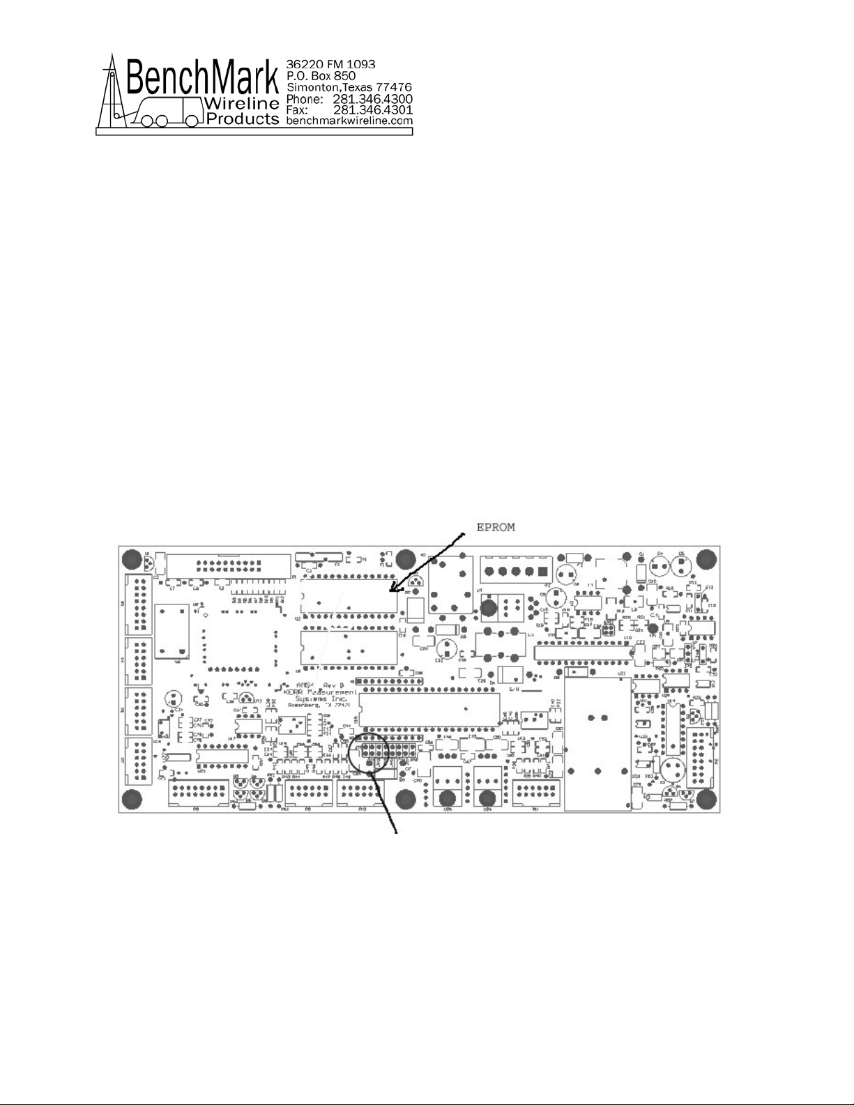
6.0 DRAWINGS AND PARTS LISTS
6.1 Main Processor Board
AMS4A040 PANEL USER MANUAL Rev H Nov 2006 Page 20 of 39
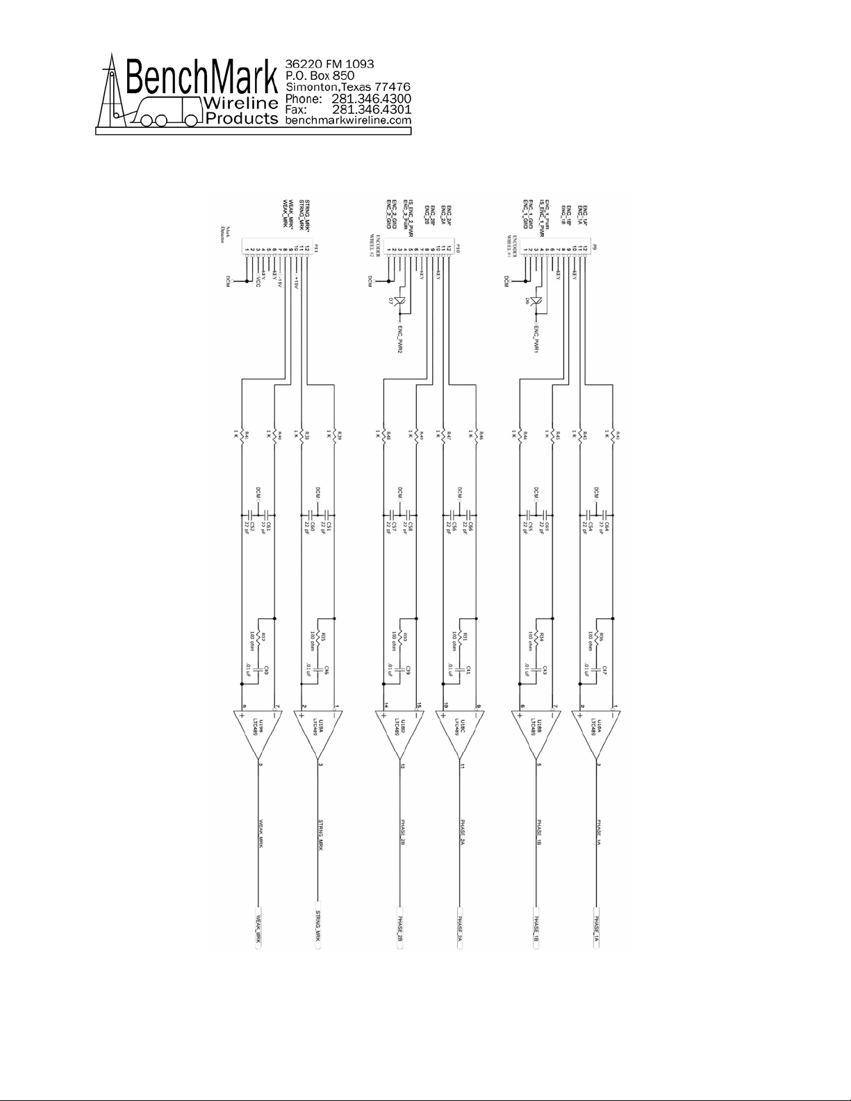
6.1.1 ENCODER AND MMD INPUTS
This manual suits for next models
2
Table of contents
Popular Automobile Accessories manuals by other brands

Hayman Reese
Hayman Reese 03371RW installation instructions

Havis-Shields
Havis-Shields 1996-2006 Ford Taurus C-TCB-10 Install instructions

benbat
benbat Oly BM 701 Instructions for use

Federal Signal Corporation
Federal Signal Corporation Legend LGD Installation, operation and service manual

Z Automotive
Z Automotive Double Bypass installation instructions

Edge
Edge CS2 Quick install guide


