manuals.online logo
Brands
  1. Home
  2. •
  3. Brands
  4. •
  5. Metra Electronics
  6. •
  7. Automobile Accessories
  8. •
  9. Metra Electronics 108-MI1 User manual

Metra Electronics 108-MI1 User manual

Metra. The World’s Best Kits.®MetraOnline.com © COPYRIGHT 2020 METRA ELECTRONICS CORPORATION REV. 12/8/20 INST108-MI1
INSTALLATION INSTRUCTIONS
108-MI1
Patent Pending
Attention! Let the vehicle sit with the key
out of the ignition for a few minutes before
removing the factory radio. When testing the
aftermarket equipment, ensure that all factory
equipment is connected before cycling the
key to ignition.
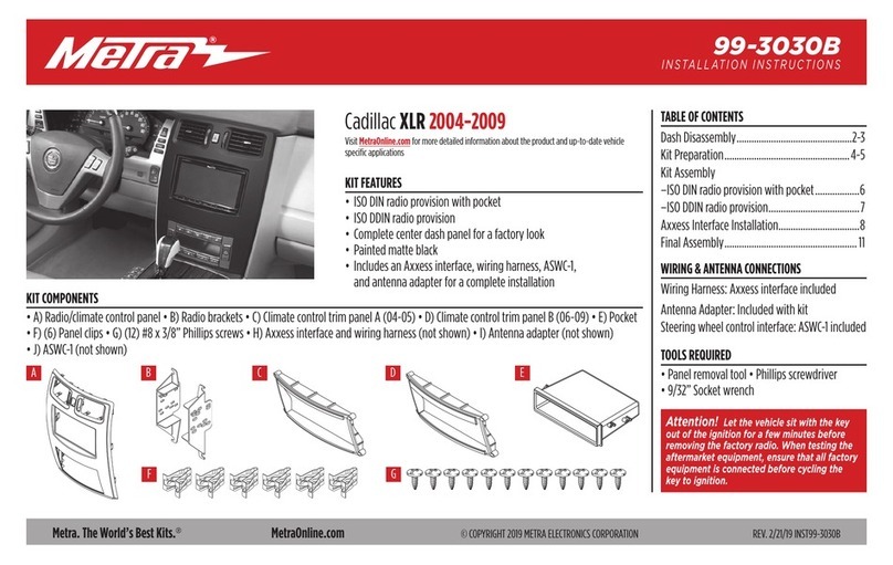
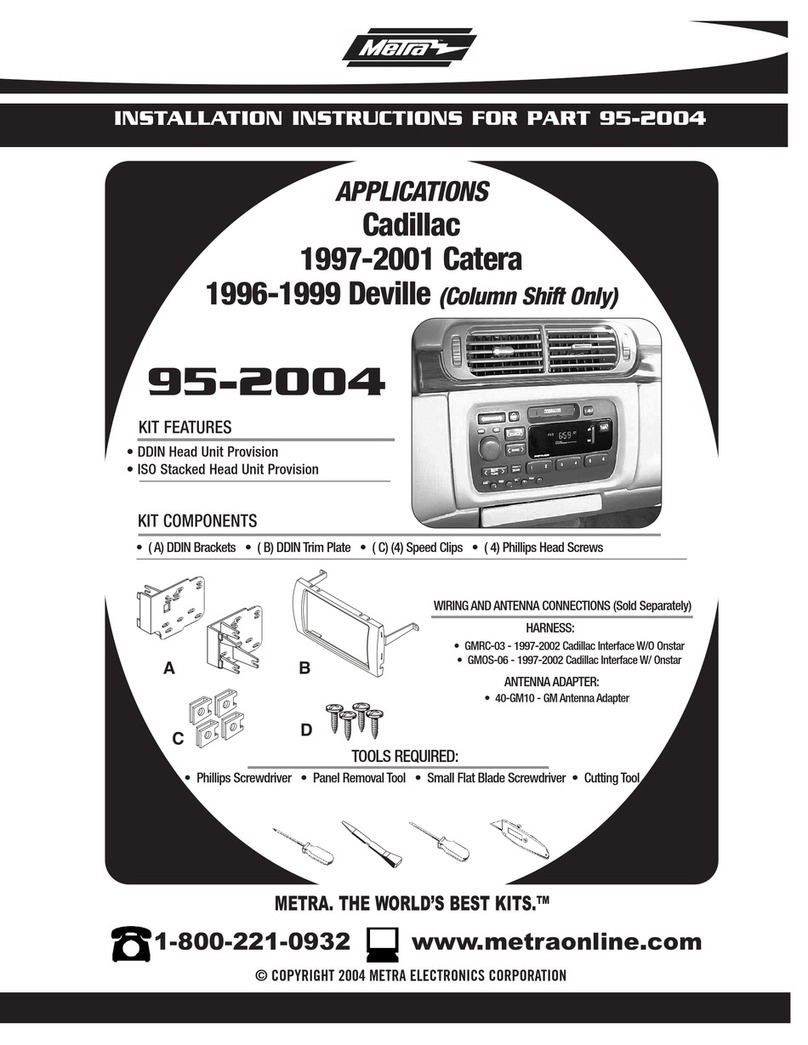
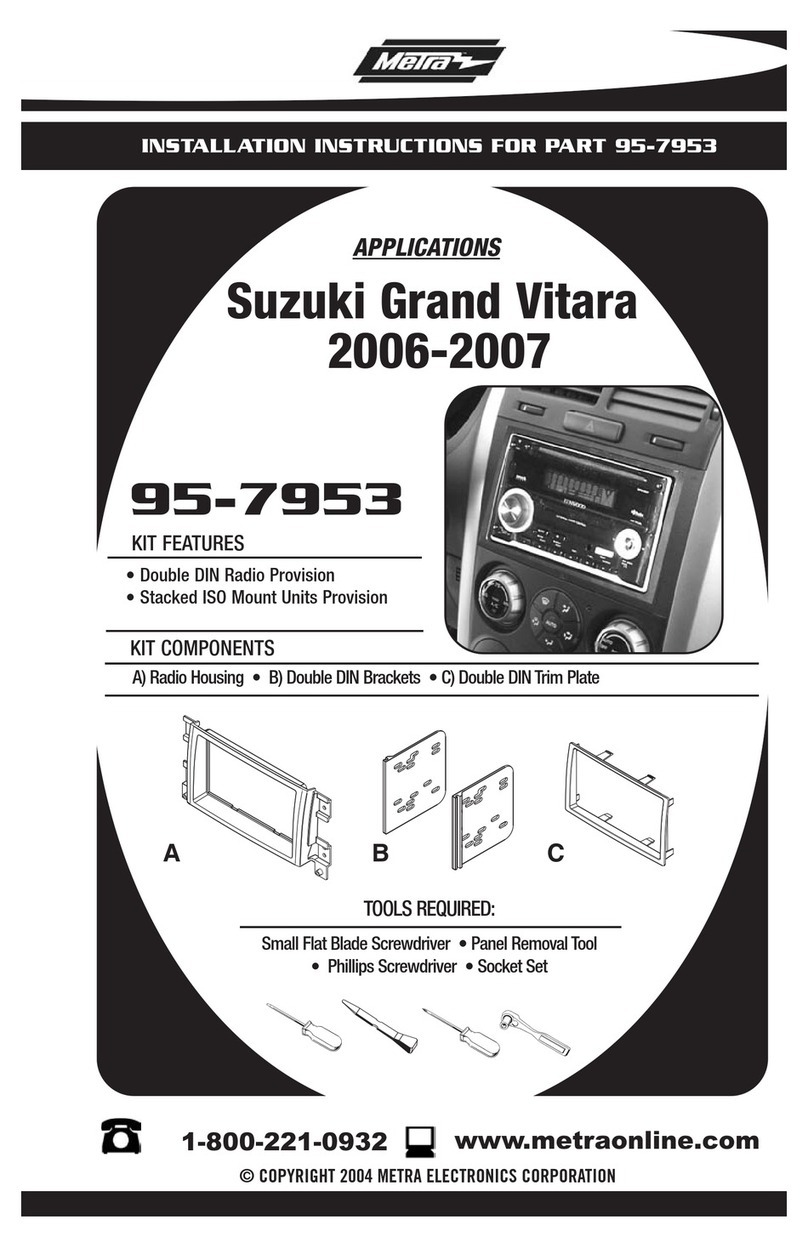
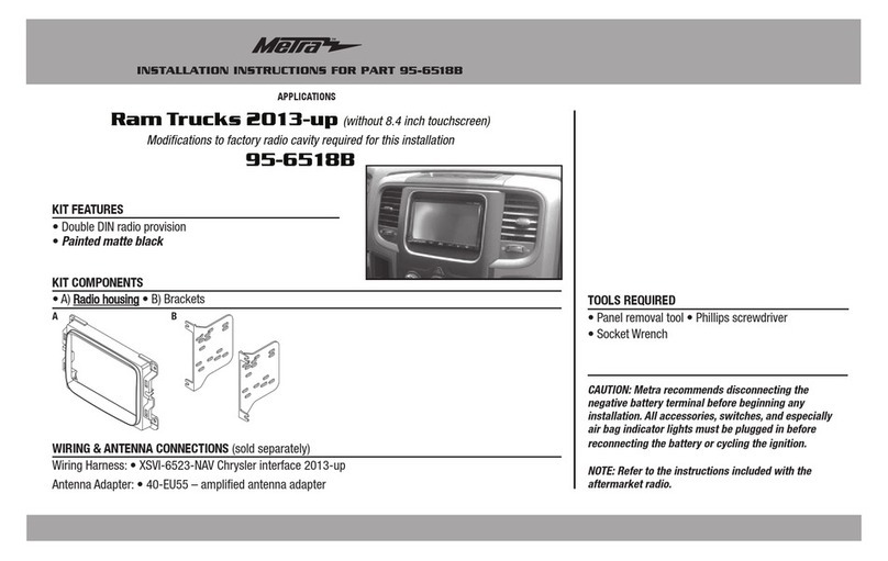
KIT FEATURES
• Designed specifically for the Pioneer 8” modular radio DMH-C5500NEX.
(Refer to the radio manufacturer for current models)
• Blank-out included for factory radio controls removed from upper panel
KIT COMPONENTS
• A) Assembly mount • B) Radio chassis brackets • C) Display brackets • D) Display housing • E) Display Trim ring • F) Block out panel
• G) 4mm Allen head Screws (4)
TOOLS REQUIRED
• 10mm socket set • Lots of different Torx
• Allen head driver • Cutting tool
• Panel removal tool • Phillips screwdriver
TABLE OF CONTENTS
Dash Disassembly ..............................................2-6
Kit Preparation .......................................................6
Kit Assembly ..........................................................7
WIRING & ANTENNA CONNECTIONS
(sold separately)
Wiring Harness: LC-BMRC-01
Antenna Adapter: 40-EU10
A CB
G
D E F
Mini Countryman & Paceman 2011-2016
Visit MetraOnline.com for more detailed information about the product and up-to-date vehicle
specific applications
(without factory NAV)
1.800.221.0932
|
MetraOnline.com
2
1. Unclip and remove the trim panel to the
right of the glove box above the
kick panel. (Figure A)
2. Unclip and remove the passenger side
kick panel. (Figure B)
3. Remove (2) Torx screws (facing up) from
the panel below the glove box then
unclip the front edge of the panel and
let hang. (Figure C)
Continued on the next page (Figure B)(Figure A) (Figure C)
DASH DISASSEMBLY
REV. 12/8/2020 INST108-MI1 3
4. Remove (7) Torx screws (2 on bottom,
3 on top edge with door open, and 2
from right side) securing the glove box
then unclip and remove the glove box
assembly. (Figures D, E)
(Figure D)
DASH DISASSEMBLY (CONT.)
(Figure E) (Figure G)
5. Unclip and remove the panel to the left
of the driver’s side knee bolster panel.
(Figure F)
6. Remove (3) Torx screws securing the
knee bolster panel then unclip and
remove the panel. (Figure G)
Continued on the next page
(Figure F)
1.800.221.0932
|
MetraOnline.com
4
DASH DISASSEMBLY (CONT.)
(Figure H) (Figure J)
7. Pull the rubber cover in the center
console back to reveal (1) Torx screw on
shifter trim panel. (Figure H)
8. Remove (2) Torx screws from inside
the cup holders and the (1) Torx screw
exposed in step 7 then unclip and slide
the shifter trim panel rearward (toward
rear of vehicle). (Figure I)
9. Remove (1) Torx screw from the trim
panel in front of the shifter trim panel
then unclip and remove the panel.
(Figure J)
10. Unclip and remove the side trim panels
from the center stack panel. (Figure K)
Continued on the next page
(Figure I) (Figure K)
REV. 12/8/2020 INST108-MI1 5
DASH DISASSEMBLY (CONT.)
(Figure L)
11. Unclip and remove the trim panel
surrounding the speedometer and
a/c vents. (Figure L)
12. Remove (10) Torx screws from the center
stack surrounding the a/c controls and
window switches then unclip disconnect
and remove the center stack. (Figure M)
(Figure M)
(Figure N)
(Figure O)
13. Remove (7) Torx screws securing
the sub trim panel surrounding the
speedometer and a/c vents then unclip
and remove the panel. (Figure N)
14. Remove (5) Torx screws securing the
radio/speedometer assembly then
disconnect and remove the entire
assembly. (Figure O)
Continued on the next page
1.800.221.0932
|
MetraOnline.com
6
(Figure P) (Figure A)
(Figure B)(Figure Q)
DASH DISASSEMBLY (CONT.) KIT PREPARATION
15. Push the two clips in on the back of the
speedometer and lift up carefully to
separate the chassis and speedometer,
then unplug the ribbon cable and set
speedometer aside for reassembly.
(Figures P,Q)
Continue to Kit Preparation
16. Remove (4) Torx screws securing the
radio controls, then remove the entire
assembly from the speedometer.
(Figure A)
17. Secure the block out panel to the
speedometer using (2) of the factory
screws. (Figure B)
Continue to Kit Assembly
Press shaded area to
release the speedometer
REV. 12/8/2020 INST108-MI1 7
KIT ASSEMBLY
Note: For steps 2 and 5, reference the
installation manual provided with the radio
for which hardware to use. The display
screen and radio chassis use two different
types of screws.
1. Secure the display brackets to the
assembly mount using (4) Allen head
screws provided. (Figure A)
Note: The brackets have a locking pin on
them which must face outwards.
2. Secure the radio brackets to the radio
chassis using (4) screws supplied with
the radio. (Figure B)
3. Slide the radio chassis/bracket assembly
into the dash. Secure the assembly
mount/display bracket assembly to the
radio brackets using the factory screws
(Figure C)
4. Route the RGB display cable from the
radio chassis, through the opening in
the assembly mount.
5. Secure the radio display to the display
housing using (4) screws supplied with
the radio. (Figure D)
6. Clip the display trim ring onto the
assembly. (Figure E)
7. Plug the RGB display cable into the
display, then slide and lock in place the
display housing to the display brackets.
Use the (4) lower holes in the display
housing (Figure F)
Note: The locking pins can be pulled
back to release the display housing.
(Figure A) (Figure D)
(Figure B) (Figure E)
(Figure C) (Figure F)
KNOWLEDGE IS POWER
Enhance your installation and fabrication skills by
enrolling in the most recognized and respected
mobile electronics school in our industry.
Log onto www.installerinstitute.com or call
800-354-6782 for more information and take steps
toward a better tomorrow.
®
Metra recommends MECP
certified technicians
Metra. The World’s Best Kits.®MetraOnline.com © COPYRIGHT 2020 METRA ELECTRONICS CORPORATION REV. 12/8/20 INST108-MI1
INSTALLATION INSTRUCTIONS
108-MI1
Having difficulties? We’re here to help.
Contact our Tech Support line at:
386-257-1187
Or via email at:
techsupport@metra-autosound.com
Tech Support Hours (Eastern Standard Time)
Monday - Friday: 9:00 AM - 7:00 PM
Saturday: 10:00 AM - 7:00 PM
Sunday: 10:00 AM - 4:00 PM

Other Metra Electronics Automobile Accessories manuals
Metra Electronics 95-9607B User manual

Metra Electronics

Metra Electronics 95-9607B User manual

Metra Electronics 95-8202 User manual

Metra Electronics

Metra Electronics 95-8202 User manual

Metra Electronics 99-5841B User manual

Metra Electronics

Metra Electronics 99-5841B User manual

Metra Electronics 70-2103T User manual

Metra Electronics

Metra Electronics 70-2103T User manual

Metra Electronics 99-7001 User manual

Metra Electronics

Metra Electronics 99-7001 User manual

Metra Electronics 99-9014HG User manual

Metra Electronics

Metra Electronics 99-9014HG User manual

Metra Electronics 95-9308B User manual

Metra Electronics

Metra Electronics 95-9308B User manual

Metra Electronics 95-8904B User manual

Metra Electronics

Metra Electronics 95-8904B User manual

Metra Electronics 70-1787 User manual

Metra Electronics

Metra Electronics 70-1787 User manual

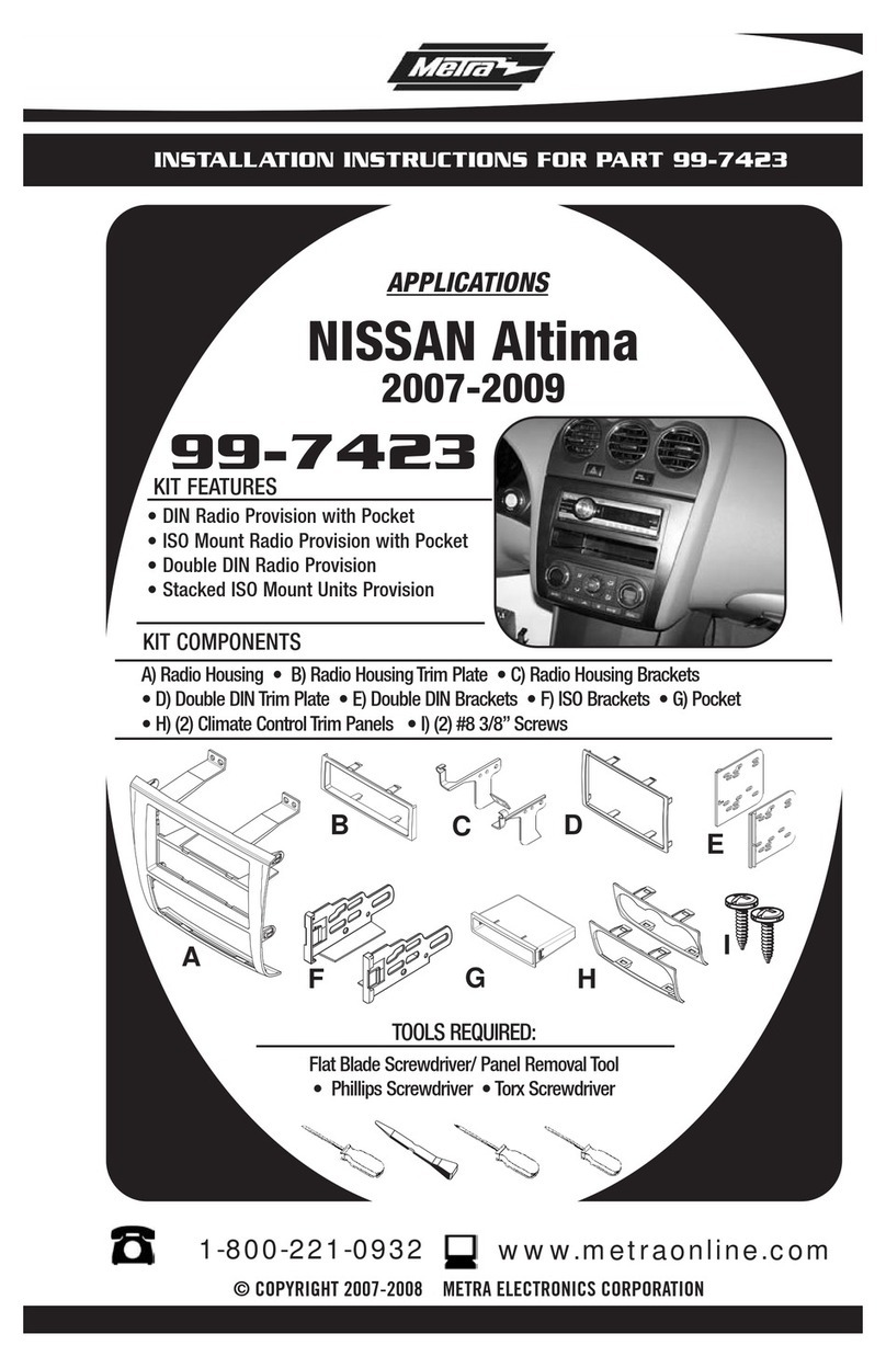
Metra Electronics 99-7423 User manual

Metra Electronics

Metra Electronics 99-7423 User manual

Metra Electronics 99-6507 User manual

Metra Electronics

Metra Electronics 99-6507 User manual

Metra Electronics 71-7552 Instruction Manual

Metra Electronics

Metra Electronics 71-7552 Instruction Manual

Metra Electronics 108-FD7B User manual

Metra Electronics

Metra Electronics 108-FD7B User manual

Metra Electronics 95-5817 User manual

Metra Electronics

Metra Electronics 95-5817 User manual

Metra Electronics 99-3014G User manual

Metra Electronics

Metra Electronics 99-3014G User manual

Metra Electronics 99-7579 User manual

Metra Electronics

Metra Electronics 99-7579 User manual

Metra Electronics 99-7517S User manual

Metra Electronics

Metra Electronics 99-7517S User manual

Metra Electronics 107-MZ1B User manual

Metra Electronics

Metra Electronics 107-MZ1B User manual

Metra Electronics 99-5838CH User manual

Metra Electronics

Metra Electronics 99-5838CH User manual

Metra Electronics 99-7300 User manual

Metra Electronics

Metra Electronics 99-7300 User manual

Metra Electronics XIAH-FD2 User manual

Metra Electronics

Metra Electronics XIAH-FD2 User manual

Metra Electronics 99-7617HG User manual

Metra Electronics

Metra Electronics 99-7617HG User manual

Metra Electronics 99-5801 User manual

Metra Electronics

Metra Electronics 99-5801 User manual

Metra Electronics 95-7951 User manual

Metra Electronics

Metra Electronics 95-7951 User manual

Popular Automobile Accessories manuals by other brands

IDEC HT3P instruction sheet

IDEC

IDEC HT3P instruction sheet

BURY CC 9060 Plus manual

BURY

BURY CC 9060 Plus manual

Motorola VC6000 Series Product reference guide

Motorola

Motorola VC6000 Series Product reference guide

Signet FC50K-CC manual

Signet

Signet FC50K-CC manual

Pioneer CA-HM-UNI-EVO.009 installation manual

Pioneer

Pioneer CA-HM-UNI-EVO.009 installation manual

Summit SUM-836 Installation instruction

Summit

Summit SUM-836 Installation instruction

Gecko GG520012 User manual and warranty

Gecko

Gecko GG520012 User manual and warranty

KEKO K189 Assembly manual

KEKO

KEKO K189 Assembly manual

Car-Interface CI-RL4-SY3-R5 manual

Car-Interface

Car-Interface CI-RL4-SY3-R5 manual

Jacob Jensen Electronic Parking Disc user guide

Jacob Jensen

Jacob Jensen Electronic Parking Disc user guide

Camoplast ATV T4S Installation guidelines

Camoplast

Camoplast ATV T4S Installation guidelines

SuperATV PR-P-RAN-09 installation instructions

SuperATV

SuperATV PR-P-RAN-09 installation instructions

Brodit ProClip 804729 installation instructions

Brodit

Brodit ProClip 804729 installation instructions

Innova OBD2 owner's manual

Innova

Innova OBD2 owner's manual

Cruz 923-05x Assembly instructions

Cruz

Cruz 923-05x Assembly instructions

AL-KO V500 BASIC quick start guide

AL-KO

AL-KO V500 BASIC quick start guide

WeatherTech No-Drill MudFlap installation instructions

WeatherTech

WeatherTech No-Drill MudFlap installation instructions

Go Rhino 390325 installation instructions

Go Rhino

Go Rhino 390325 installation instructions

manuals.online logo
manuals.online logoBrands
  • About & Mission
  • Contact us
  • Privacy Policy
  • Terms and Conditions

Copyright 2025 Manuals.Online. All Rights Reserved.