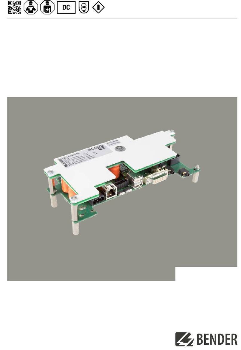
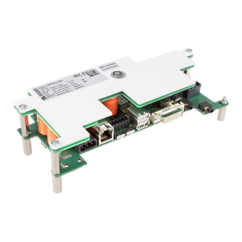
Bender COMTRAXX CP9-Kit Series User manual

Manual
EN
CP9xx-Kit_D00399_00_M_XXEN/07.2019
COMTRAXX® CP9xx–Kit
Installation kit graphical interface
Softwareversion: V3.xx

© Bender GmbH & Co. KG
All rights reserved.
Reprinting only with permission
of the publisher.
Subject to change!
Bender GmbH & Co. KG
P.O.Box 1161 • 35301 Gruenberg • Germany
Londorfer Straße 65 • 35305 Gruenberg • Germany
Tel.: +49 6401 807-0 • Fax: +49 6401 807-259
Photos: Bender Archive

3
Table of Content
CP9xx-Kit_D00399_00_M_XXEN/07.2019
1. Important information ........................................................................................... 5
1.1 How to use this manual ......................................................................................................... 5
1.2 Technical support: service and support ........................................................................... 6
1.2.1 End customer support and consulting .................................................................... 6
1.2.2 Repair ................................................................................................................................... 6
1.2.3 Customer service ............................................................................................................. 6
1.3 Training courses ....................................................................................................................... 6
1.4 Delivery conditions ................................................................................................................. 7
1.5 Inspection, transport and storage ..................................................................................... 7
1.6 Warranty and liability ............................................................................................................. 7
1.7 Disposal ....................................................................................................................................... 7
2. Safety instructions .................................................................................................. 9
2.1 General safety instructions ................................................................................................... 9
2.2 Work activities on electrical installations ........................................................................ 9
2.3 Intended use .............................................................................................................................. 9
3. Product description ............................................................................................. 11
3.1 Scope of delivery ................................................................................................................... 11
3.2 Device features ...................................................................................................................... 11
3.3 Range of functions of the CP9… alarm indicator
and operator panel ............................................................................................................... 11
3.4 Applications ............................................................................................................................ 11
3.5 Function ................................................................................................................................... 12
3.6 Software products used ...................................................................................................... 12
3.7 Functional description ........................................................................................................ 12
3.7.1 Interfaces ......................................................................................................................... 12
3.7.2 Process image ................................................................................................................ 12
3.7.3 List of compatible BMS devices ............................................................................... 12
3.8 BMS side of the CP9… display an operator panel .................................................... 12
3.9 Address configuration and termination ....................................................................... 13
4. Installation, connection and commissioning CP9xx-Kit ............................... 15
4.1 Installation of the CP9xx-Kit .............................................................................................. 15
4.1.1 Dimension diagram ..................................................................................................... 15
4.2 Mounting on a mounting plate ....................................................................................... 15
4.2.1 Drillholes .......................................................................................................................... 16

Table of Content
4CP9xx-Kit_D00399_00_M_XXEN/07.2019
4.3 Connection of the CP9xx-Kit .............................................................................................. 16
4.4 Connections ............................................................................................................................ 17
4.4.1 Factory settings communication addresses ........................................................ 17
4.5 Digital inputs and outputs ................................................................................................. 19
4.5.1 Functions .......................................................................................................................... 19
4.5.2 Mode .................................................................................................................................. 19
4.5.3 Response times t(on)/t(off) ....................................................................................... 19
4.6 Commissioning of the CP9… device .............................................................................. 20
4.7 COMTRAXX® user interface of the CP9xx-Kit ............................................................... 21
5. Modbus TCP server .............................................................................................. 23
5.1 Data access using Modbus TCP protocol ...................................................................... 23
5.1.1 Exception code ............................................................................................................... 23
5.1.2 Modbus requests ........................................................................................................... 23
5.1.3 Modbus responses ........................................................................................................ 23
5.1.4 Structure of the exception code .............................................................................. 24
5.1.5 Modbus address structure for BMS devices ......................................................... 24
5.2 Modbus process image in the memory of the CP9… .............................................. 24
5.2.1 Querying data ................................................................................................................. 24
5.2.2 Memory scheme of the process image ................................................................. 25
5.2.3 Modbus examples to read out data ........................................................................ 30
5.2.4 Reference data records of the process image ..................................................... 30
5.2.5 Channel descriptions for the process image ....................................................... 31
5.2.6 Modbus control commands ...................................................................................... 35
6. Troubleshooting ................................................................................................... 38
6.1 Malfunctions ............................................................................................................................ 38
6.1.1 What should be checked? .......................................................................................... 38
6.1.2 Frequently asked questions ....................................................................................... 38
6.2 Maintenance ............................................................................................................................ 38
7. Technical data ....................................................................................................... 39
7.1 Ordering details ...................................................................................................................... 42
7.1.1 Devices .............................................................................................................................. 42
7.1.2 Accessories ....................................................................................................................... 42
7.1.3 Standards, approvals and certifications ................................................................ 42
Index ............................................................................................................................ 43

5
CP9xx-Kit_D00399_00_M_XXEN/07.2019
1. Important information
1.1 How to use this manual
This manual describes the installation kit of the CP9xx-device family.
Before using the devices please read:
This manual. It describes the installation, commissioning and use of the installation kit CP9xx-Kit.
The "COMTRAXX®" manual. It describes the functions of the web user interface.
The supplement "Important safety instructions for BENDER products".
The manuals for the system components.
And the separate manuals which describe the interfaces:
The "BCOM" manual
The "BMS bus" package slip
COMTRAXX® is a registered trademark of Bender GmbH & Co. KG.
Always keep this manual within easy reach for future reference.
We have used symbols to identify important instructions and information:
This manual is intended for qualified personnel working in electrical enginee-
ring and electronics.
This signal word indicates that there is a high risk of danger, that will result in
death or serious injury if not avoided.
This signal word indicates a medium risk of danger that can lead to death or
serious injury, if not avoided.
This signal word indicates a low-level risk that can result in minor or mode-
rate injury or damage to property if not avoided.
This symbol denotes information intended to assist the user in making
optimum use of the product.
DANGER
WARNING
CAUTION

Important information
6CP9xx-Kit_D00399_00_M_XXEN/07.2019
1.2 Technical support: service and support
For commissioning and troubleshooting Bender offers:
1.2.1 End customer support and consulting
Technical support by phone or e-mail for all Bender products
Questions about specific customer applications
Commissioning
Troubleshooting
Telephone: +49 6401 807-760*
Fax: +49 6401 807-259
In Germany only: 0700BenderHelp (telephone and fax)
E-mail: [email protected]
1.2.2 Repair
Repair, calibration, update and replacement service for Bender products
Repair, calibration, testing and analysis of Bender products
Hardware and software update for Bender devices
Delivery of replacement devices for faulty or incorrectly delivered Bender devices
Extended warranty for Bender devices with in-house repair service or replacement devices at no extra
cost
Telephone: +49 6401 807-780** (technical issues)/
+49 6401 807-784**, -785** (commercial issues)
Fax: +49 6401 807-789
E-mail: [email protected]
Please send the devices for repair to the following address:
Bender GmbH, Repair-Service,
Londorfer Straße 65,
35305 Grünberg
1.2.3 Customer service
On-site service for all Bender products
Commissioning, parameter setting, maintenance, troubleshooting for Bender products
Analysis of the electrical installation in the building (power quality test, EMC test, thermography)
Practical training courses for customers
Telephone: +49 6401 807-752**, -762 ** (technical issues)/
+49 6401 807-753** (commercial issues)
Fax: +49 6401 807-759
E-mail: fieldservice@bender-service.de
Internet: www.bender.de
*Available from 7.00 a.m. to 8.00 p.m. on 365 days of the year (CET/UTC +1)
**Mo-Thu 7.00 a.m. - 4.00 p.m., Fr 7.00 a.m. - 1.00 p.m
1.3 Training courses
Bender is happy to provide training regarding the use of test equipment. The dates of training courses and
workshops can be found on the Internet at www.bender.de -> Know-how -> Seminars.

Important information
7
CP9xx-Kit_D00399_00_M_XXEN/07.2019
1.4 Delivery conditions
The conditions of sale and delivery set out by Bender apply. These can be obtained from Bender in printed or
electronic format.
For software products, the "Softwareklausel zur Überlassung von Standard- Software als Teil von Lieferungen,
Ergänzung und Änderung der Allgemeinen Lieferbedingungen für Erzeugnisse und Leistungen der Elektroin-
dustrie" (software clause in respect of the licensing of standard software as part of deliveries, modifications and
changes to general delivery conditions for products and services in the electrical industry) set out by the Zen-
tralverband Elektrotechnik- und Elektronikindustrie e.V. (German Electrical and Electronic Manufacturers' As-
sociation) applies.
1.5 Inspection, transport and storage
Inspect the dispatch and equipment packaging for damage, and compare the contents of the package with the
delivery documents. In the event of damage in transit, please contact Bender immediately.
The devices must only be stored in areas where they are protected from dust, humidity and spray or dripping
water, and in which the specified storage temperatures are not exceeded.
1.6 Warranty and liability
Warranty and liability claims in the event of injury to persons or damage to property are excluded if they can
be attributed to one or more of the following causes:
Improper use of the device.
Incorrect mounting, commissioning, operation and maintenance of the device.
Failure to observe the instructions in this operating manual regarding transport, commissioning, ope-
ration and maintenance of the device.
Unauthorised changes to the device made by parties other than the manufacturer.
Non-observance of technical data.
Repairs carried out incorrectly and the use of replacement parts or accessories not approved by the
manufacturer.
Catastrophes caused by external influences and force majeure.
Mounting and installation with device combinations not recommended by the manufacturer.
This operating manual, especially the safety instructions, must be observed by all personnel working on the de-
vice. Furthermore, the rules and regulations that apply for accident prevention at the place of use must be ob-
served.
1.7 Disposal
Abide by the national regulations and laws governing the disposal of this device. Ask your supplier if you are
not sure how to dispose of the old equipment.
The directive on waste electrical and electronic equipment (WEEE directive) and the directive on the restriction
of certain hazardous substances in electrical and electronic equipment (RoHS directive) apply in the European
Community. In Germany, these policies are implemented through the "Electrical and Electronic Equipment
Act" (ElektroG). According to this, the following applies:
Electric and electronic equipment are not to be included in household waste.
Batteries and accumulators are not to be included in household waste but must be disposed of in
accordance with the regulations.
Old electrical and electronic equipment from users other than private households which was introdu-
ced to the market after 13th August 2005 must be taken back by the manufacturer and disposed of
properly.
For more information, refer to our website at www.bender.de -> Service & support.

9
CP9xx-Kit_D00399_00_M_XXEN/07.2019
2. Safety instructions
2.1 General safety instructions
Part of the device documentation in addition to this manual is the enclosed supplement " Safety instructions
for Bender products".
2.2 Work activities on electrical installations
If the device is being used in a location outside the Federal Republic of Germany, the applicable local standards
and regulations must be complied with. The European standard EN 50110 can be used as a guide.
2.3 Intended use
CP9… alarm indicator and operator panels and the installation kit CP9xx-Kit show alarms, measured values
and states of devices.
These include, for example:
All Bender devices with BMS bus or BCOM interface
Bender devices (PEM, energy meters,…) with Modbus RTU or Modbus TCP interface
Other devices with Modbus RTU or Modbus TCP interface
In addition, the data is available via the Modbus TCP protocol. This allows coupling to a higher-level building
control system as well as visualisation and evaluation using standard web browsers.
Operation and settings are made via the COMTRAXX® user interface integrated in the device.
Any other use than that described in this manual is regarded as improper.
Only qualified personnel are permitted to carry out the work necessary to in-
stall, commission and run a device or system.
Risk of fatal injury due to electric shock!
Touching live parts of the system carries the risk of:
An electric shock
Damage to the electrical installation
Destruction of the device
Before installing and connecting the device, make sure that the installa-
tion has been de-energised. Observe the rules for working on electrical ins-
tallations.
DANGER

11
CP9xx-Kit_D00399_00_M_XXEN/07.2019
3. Product description
3.1 Scope of delivery
You will receive:
The CP9… alarm indicator and operator panel
A printed quick reference guide
The sheet "Safety instructions for Bender products"
The "COMTRAXX® CP9… - Control Panel", "COMTRAXX®" and "BCOM" manuals as PDF files. You can
obtain the manuals at:
http://www.bender.de > Service & support > Download > Operating manuals
3.2 Device features
Universal alarm indicator and operator panel for Bender systems:
User-friendly touch-sensitive monitoring system for medical installations and other applications
Clear menu structure and intuitive operation
Silent due to operation without fan
High display resolution, high contrast, wide viewing angle
Visualised integration of building plans or status displays in photo quality
Integration of external subsections like charging stations for operating theatre table controls and inter-
com systems with front foil
Screwless mounted front plate. Glass or antibacterial foil surface
Simple conversion and expansion with minimal service interruptions
3.3 Range of functions of the CP9… alarm indicator
and operator panel
Main functions:
Indication and visualisation of system conditions, warning and alarm messages
Centralised monitoring, control and parameter setting
Output of visual and acoustic messages
Indication of present measured values and parameterisation of setpoints
Application examples: IT systems, supply systems for medical gases, air conditioning and ventilation systems,
room lighting, communication systems, operating theatre lights, special power supply systems
3.4 Applications
Optimal visualisation on the display tailored to the user
Integration of all compatible Bender products (ISOMETER®, ATICS®, RCMS, EDS, Linetraxx® and MEDICS®
systems, universal measuring devices and energy meters)
Individual instructions in case of alarms
Selective notification to various users in case of alarms
Control and regulation of systems such as air conditioning or blinds control.

Product description
12 CP9xx-Kit_D00399_00_M_XXEN/07.2019
3.5 Function
CP9… alarm indicator and operator panels are integrated into the existing EDP structure like PCs. After con-
nection to the network and compatible Bender products, all system devices can be accessed from any PC using
a web browser. In this way, all important system information is directly available. Verified web browsers: Mi-
crosoft IE, Mozilla Firefox, Google Chrome
The possibility of integrating all technical equipment into a single panel creates a "technical monitoring centre"
in the respective room. Each panel is individually manufactured and tailored to the requirements of the user.
3.6 Software products used
CP9… devices are equipped with the COMTRAXX® user interface. It is described separately in the "COMTRAXX"
manual.
3.7 Functional description
3.7.1 Interfaces
CP9… devices communicate with the devices and systems assigned via various interfaces:
Internal BMS bus (RS-485) for Bender systems such as EDS46x/49x, RCMS46x/49x and MEDICS. CP9…
devices can be operated as a master or as a slave. When operated as a master, requests are answered
more quickly. The devices can only be operated on the internal BMS bus.
BCOM for new and future Bender systems, such as ISOMETER® iso685-D.
Modbus RTU (RS-485) when operated as a master for Bender universal measuring devices PEM..3 and
also PEM..5 with restricted functionality (full functionality of PEM..5 only via Modbus TCP).
Modbus TCP (Ethernet) for Bender universal measuring devices PEM..5
3.7.2 Process image
The CP9… alarm indicator and operator panel combines the information from the different interfaces and ma-
kes it available for operation and visualisation via the web user interface of a PC.
It acts as a central user interface. In order to be able to identify them, one individual address is available for each
device on this interface. BMS, BCOM and Modbus RTU devices receive the appropriate address for their inter-
face. A virtual address is assigned to Modbus TCP devices.
3.7.3 List of compatible BMS devices
An updated list of parametrisable devices can be found on our homepage
http://www.bender.de .Enter the term "Compatibility list" in the search field.
3.8 BMS side of the CP9… display an operator panel
The majority of Bender devices communicate via the internal BMS bus.
The CP9… alarm indicator and operator panel can be operated as a master or as a slave.
The CP9… alarm indicator and operator panel is to be operated as a master if
- Parameters are queried or changed
- Certain control commands are issued
Please note that not all BMS masters can surrender their master function!

Product description
13
CP9xx-Kit_D00399_00_M_XXEN/07.2019
3.9 Address configuration and termination
To ensure proper functioning of the CP9… alarm indicator and operator panel, correct address assignment
and termination is of utmost importance.
Multiple assignment of addresses
The factory setting for the system name on all Bender BCOM devices is "SYS-
TEM". If several systems with the same system name are integrated into the sa-
me network, addresses are assigned twice. This leads to transmission errors.
Always enter a unique BCOM system name during initial configuration.

15
CP9xx-Kit_D00399_00_M_XXEN/07.2019
4. Installation, connection and commissioning CP9xx-Kit
The CP9… touch panel is integrated into existing LAN structures, but can also be operated via a single PC.
4.1 Installation of the CP9xx-Kit
4.1.1 Dimension diagram
Abb. 4.1: Dimensions of a CP9xx-Kit device
4.2 Mounting on a mounting plate
Abb. 4.2: Drillholes of the CP9xx-Kit
Only qualified personnel are permitted to carry out the work necessary to ins-
tall, commission and run a device or system.
Configuration of computer networks
If you are familiar with the configuration of computer networks, you can carry
out the connection of the CP9… alarm indicator and operator panel yourself.
Otherwise please contact your EDP administrator!
* Functional ground. The device must be earthed. Without connection of the
functional earth (PE), the device function is not guaranteed.
Touch-sensitive components
During assembly, the rules for handling touch-sensitive electronic components
must be observed.
90 200
54
Dimensions in mm
Ø M4 / 0,6 Nm Ø M4 / 0,6 Nm
i
i
Erdung der Montageplatte ist zwingend erforderlich!
CAUTION

Installation, connection and commissioning CP9xx-Kit
16 CP9xx-Kit_D00399_00_M_XXEN/07.2019
4.2.1 Drillholes
Abb. 4.3: Drillholes of the CP9xx-Kit
4.3 Connection of the CP9xx-Kit
Abb. 4.4: Connection overview CP9xx-Kit
* Damage due to excessive torque. Tighten all screw connections with a torque
of 0.6 Nm. Otherwise the circuit boards will be damaged.
* Functional ground. The device must be earthed. Without connection of the
functional earth (PE), the device function is not guaranteed.
193
59
CAUTION
DVI USB
1 2 12
...
11 12 14
+
–
~
i
Digital I/O
Relais
Relay
BMS-Bus
Modbus RTU
Ethernet
Ethernet (1:1)
*
CAUTION

Installation, connection and commissioning CP9xx-Kit
17
CP9xx-Kit_D00399_00_M_XXEN/07.2019
4.4 Connections
4.4.1 Factory settings communication addresses
CP9… devices are delivered with the following factory settings:
Some of the settings can be changed during commissioning via the display or the web user interface.
If you are familiar with the configuration of computer networks, you can carry
out the connection of the CP9… alarm indicator and operator panel yourself.
Otherwise please contact your EDP administrator!
For UL-applications:
Minimum temperature rating of the cable to be connected to the field wiring ter-
minals: 75 °C
No. Connection No. Connection
1Plug connector digital inputs 8Termination of Modbus RTU and BMS bus
2I²C interface 9USB ports (for touch sensor)
3Plug connector to energy storage board 10 DVI output
5Voltage supply A1/+ A2/–, PE 11 Audio output
6Ethernet (RJ45/CAT5); HTTP, Modbus TCP, BCOM 12 Audio input
7X1 plug connector for Modbus RTU, BMS bus 13 Connection to control relay
Parameter Factory setting
IP address
Connection always be made via the pre-defined IP address
(e.g. for commissioning or for direct 1:1 ETH connection) 169.254.0.1
Net mask 255.255.0.0
Standard gateway 192.168.0.1
DNS -
DHCP off
toff Timeout for DCHP address assignment 30 s
BMS address 1
BMS protocol BMS i
BCOM system name SYSTEM
Subsystem address 1
BCOM device address 1
1
2
45 67
3
913
10 11 12
8

Installation, connection and commissioning CP9xx-Kit
18 CP9xx-Kit_D00399_00_M_XXEN/07.2019
Connect the CP9xx-Kit as follows:
1. Modbus RTU connection:
Connect terminals AMB and BMB (7) to the Modbus RTU (A to A, B to B).
2. BMS bus connection:
Connect terminals ABMS and BBMS (7) to the BMS bus (A to A, B to B).
3. If the CP9… is located at the beginning or end of the respective bus (Modbus RTU and BMS), the res-
pective terminating switch of the device (8) must be switched to "ON".
4. Establish connection with PC and BCOM:
Connect the CP9… device to the PC network using an Ethernet cable (6).
5. Connecting digital IN- and OUT
See Kapitel „4.5 Digital inputs and outputs".
6. Connect Relay (if required)
7. Connect voltage supply:
Connect terminals A1/+ and A2/- (5) to the voltage source. For further information, please refer to the
technical data.
8. Attach the front plate to the built-in flush-mounting box.
Damage to the device by using anincorrect connector plug
An existing connector plug of another device may have a different polarity. It is
nesessary that you use the supplied connector plug (A1+/A2-).
SBMS
ABMS
BBMS
AMB BMB
SMB
SBMS
ABMS
BBMS
AMB BMB
SMB
Terminierung
Modbus RTU
BMS-Bus
BMSModbus RTU
11 12 14
:
N/C Quiescent current circuit Contacts 11- 12
(The alarm relay is energized in normal operation)
N/O Working current circuit Contacts 11-14
(The alarm relay is de- energized in normal operation)
CAUTION

Installation, connection and commissioning CP9xx-Kit
19
CP9xx-Kit_D00399_00_M_XXEN/07.2019
9. Connect the screen output DVI (10) to the front plate. Appropriate DVI-D connecting cable included in
scope of delivery.
4.5 Digital inputs and outputs
CP9xx devices have 12 configurable digital inputs and outputs. The settings are made via the COMTRAXX® user
interface in a browser.
4.5.1 Functions
You can assign the following functions for the digital inputs:
4.5.2 Mode
The operating mode for the digital input can be set to the following values:
4.5.3 Response times t(on)/t(off)
off Digital input without function.
TEST Self test of the device.
RESET Resetting error and alarm messages.
•Active high An event is carried out on the rising edge of the digital input (low to high).
Response time t(on)/t(off) after a switch-on signal
•Active low An event is carried out on the falling edge of the digital input (high to low).
Response time t(on)/t(off) after a switch-off signal.
on The response time t(on) after a switch-on signal can be set between 100 ms and 300 s.
off The response time t(off) after a switch-on signal can be set between 100 ms and 300 s.
10
DVI-D-Anschluss Steuerplatine
1 2
3
4 5
6
7 8
9
10 11
12
LL
1 2
3
4 5
6
7 8
9
10 11
12
KK
...
K1
L1
N/O
K2
L2
N/C
K12
L12
N/O
I
x
X1 X1
+
t
0
1
t(on)
Reaktion
Impuls on
Reaktion
< t(on)
I
x
X1 X1
+
t
0
1
t(on)
Reaktion Reaktion
Impuls on
< t(on)

Installation, connection and commissioning CP9xx-Kit
20 CP9xx-Kit_D00399_00_M_XXEN/07.2019
4.6 Commissioning of the CP9… device
1. Switch on the supply voltage: After switching on, the device performs a start routine. It is completed
when the commissioning page appears n the display.
Abb. 4.5: Commissioning page CP9xx device
2. Enter the desired IP address in the 1st line
3. Enter the subnet mask in the 2nd line
4. Enter the address of the default gateway.
5. Press the "Save" button to store the entries.
6. Wait 8-10 seconds.
Other manuals for COMTRAXX CP9-Kit Series
2
This manual suits for next models
1
Table of contents
Other Bender Recording Equipment manuals


