Burkert 2510 User manual

*Betriebsanleitung Seite 2
*Operating instructions page 3
*Instructions de service page 4
*Manual de instrucciones página 5
Typ 2510 / 2511
AS-Interface
Fluid Control Systems
Betriebsanleitung / Operating instructions
Instructions de service / Manual de instrucciones
© 1999 BürkertWerke GmbH & Co.
Alle Rechte vorbehalten.
All rights reserved.
Tous droits réservés.
Reservados todos los derechos.

Typ 2510 / 2511
AS-Interface
Fluid Control Systems
Betriebsanleitung Technische Änderungen vorbehalten
Bürkert Werke GmbH Co. Alle Rechte vorbehalten
Betriebsanleitung-Nr.801 799 01/99/02
BÜRKERT GERMANY
Chr.-Bürkert-Straße 13-17 Berlin Ph: (0 30) 67 97 17 - 0
74653 Ingelfingen Dortmund Ph: (0 23 73) 96 81 - 0
Ph: (0 79 40) 10-0 Dresden Ph: (03 59 52) 36 30 - 0
Fax (0 79 40) 10-204 Frankfurt Ph: (0 61 03) 94 14 - 0
Hannover Ph: (05 11) 9 02 76 - 0
München Ph: (0 89) 82 92 28 - 0
Stuttgart Ph: (07 11) 4 51 10 - 0
BÜRKERT INTERNATIONAL
APh. (01) 8 94 13 33 Fax (01) 8 94 13 00
AUS Ph. (02) 96 74 61 66 Fax (02) 96 74 61 67
BPh. (03) 3 25 89 00 Fax (03) 3 25 61 61
CDN Ph. (9 05) 8 47 55 66 Fax (9 05) 8 47 90 06
CH Ph. (0 41) 7 85 66 66 Fax (0 41) 7 85 66 33
CZ Ph. (06 41) 22 61 80 Fax (06 41) 22 61 81
DK Ph. (0 44) 50 75 00 Fax (0 44) 50 75 75
EPh. (93) 3 71 08 58 Fax (93) 3 71 77 44
ET Ph. (0 40) 54 27 38 Fax (0 40) 54 41 65
FPh. (01) 48 10 31 10 Fax (01) 48 91 90 93
GB Ph. (0 14 53) 73 13 53 Fax (0 14 53) 73 13 43
HKG Ph. 24 80 12 02 Fax 24 18 19 45
IPh. (02) 9 52 01 59 Fax (02) 9 52 90 33
JPh. (03) 32 47 34 11 Fax (03) 32 47 34 72
KOR Ph. (02) 34 62 55 92 Fax (02) 34 62 55 94
NPh. (0 63) 84 44 10 Fax (0 63) 84 44 55
MAL Ph. (04) 6 57 66 49 Fax (04) 6 57 21 06
NL Ph. (0 34) 6 59 53 11 Fax (0 34) 6 56 37 17
NZ Ph. (09) 5 70 25 39 Fax (09) 5 70 25 73
PPh. (01) 4 42 26 08 Fax (01) 4 42 28 08
PL Ph. (0 22) 6 27 47 20 Fax (0 22) 6 27 47 20
RC Ph. (02) 27 58 31 99 Fax (02) 27 58 24 99
SPh. (0 40) 66 45 100 Fax (08) 7 24 60 22
SF Ph. (09) 5 49 70 600 Fax (09) 5 03 12 75
SGP Ph. 3 83 26 12 Fax 3 83 26 11
TR Ph. (02 32) 4 59 53 95 Fax (02 32) 4 59 76 94
USA Ph. (9 49) 2 23 31 00 Fax (9 49) 2 23 31 98
ZA Ph. (0 11) 3 97 29 00 Fax (0 11) 3 97 44 28
LIEBER KUNDE
Herzlichen Glückwunsch zum Kauf dieses Bürkert Gerätes.Lesen
Sie bitte zu Ihrer Sicherheit diese Bedienungsanleitung vor der
Installation des Gerätes genau durch.Fragen beantwortet Ihnen
gern Ihre zuständige Bürkert-Niederlassung.
Bild 1 : GerätesteckdoseTyp 2510/2511 AS-Interface,Draufsicht
1 QUICKON-Anschluß 2polig
2 M12-Buchse Eingänge1)
3 LED Eingang 2 (gelb) 1)
ein geschaltet
aus nicht geschaltet
4 LED Eingang 1 (gelb)1)
ein geschaltet
aus nicht geschaltet
5 Bus LED (gelb)
aus Power off
ein OK
blinkt Slaveadresse = 0
6 Statusanzeige LED Ausgang (grün)
ein geschaltet
aus nicht geschaltet
7 Befestigungsschraube
Bild 2 : Steckerbelegung M 12 Buchse
1 + 24 V Sensorversorgung
2 Sensoreingang 2
3 GND
4 Sensoreingang 1
Bild 3 : QUICKON-Anschluß der Gerätesteckdose
4
3
2
1
Bitte beachten Sie die Hinweise dieser Betriebsanleitung
sowie die Einsatzbedingungen und zulässigen Daten, die in
den Datenblättern der verwendeten Magnetventile sowie der
GerätesteckdoseTyp 2510/2511 AS-Interface spezifiziert sind, damit
das Gerät einwandfrei funktioniert und lange einsatzfähig bleibt:
• Halten Sie sich bei Einsatzplanung und Betrieb des Gerätes an die
allgemeinen Regeln derTechnik!
• Eingriffe dürfen nur durch Fachpersonal und mit geeignetem Werk-
zeug erfolgen!
• Treffen Sie geeignete Maßnahmen, um unbeabsichtigtes Betätigen
oder unzulässige Beeinträchtigungen auszuschließen!
• Schalten Sie vor Eingriffen in das System immer die Spannung ab!
• Bei Nichtbeachtung dieser Hinweise sowie unzulässigen Eingriffen in
das Gerät entfällt jegliche Haftung unsererseits, ebenso erlischt die
Garantie auf Geräte u.Zubehörteile!
Die GerätesteckdoseTyp 2510/2511 AS-Interface dient zum
Ansteuern von Gleichstromspulen mit Leistungen ≤ 5 W ohne
externe Spannungsversorgung.
• Watch-Dog-Funktion
HINWEIS:Bei ausbleibendem Datenverkehr wird der Ausgang nach
50 - 100 ms zurückgesetzt.
• Anschluß von 2 Sensoren an M12-Buchse (Gerätesteckdose mit
Rückmeldeeingängen)
DEUTSCH
Schalten Sie die GerätesteckdoseTyp 2510/2511 AS-Interface
vor Eingriffen spannungsfrei!
MONTAGE / INBETRIEBNAHME
• Schließen Sie die Rundleitung (2 x 0,75 - 1,5 mm2) laut Anschluß-
plan an (Bild 3):
- Leitungsummantelung ca.15 mm entfernen
- Überwurfmutter (1), Klemmhülse (2) und Dichtung (3) aufschieben
- Spleißring aufstecken (4):
ACHTUNG! Polung: 1 = Bus+ 2 = Bus-
• Stecken Sie die Zylinderschraube durch die Gerätesteckdose
• Schieben Sie die Flachdichtung auf die Steckerfahnen des Magnet-
ventils
• Stecken Sie die Gerätesteckdose auf
• Sichern Sie die Gerätesteckdose mit der Zylinderschraube (max.
Anzugsdrehmoment 1 Nm)
ACHTUNG! Achten Sie beimVerschrauben der Gerätesteckdose mit
dem Magnetventil auf den einwandfreien Sitz der Dichtung!
PROGRAMMIERDATEN
E/A-Konfiguration B hex (1 Ausgang, 2 Eingänge)
ID-Code F hex (Belegung siehe unten)
voreingestellte Adresse 0
Belegung der Datenbits
D3 D2 D1 D0
IN 11) IN 21) - OUT
GERÄTESTECKDOSE MIT RÜCKMELDEEINGÄNGEN
• Über die M 12 Buchse können 2 Sensoren mit einem
Y-Verteiler angeschlossen werden (s.Bild 2)
Typ Rückmeldeeingänge Bestell-Nr.
2510 nein 139 202 G
2510 ja 140 069 J
2511 nein 140 071 C
2511 ja 140 070 P
Tabelle 1: Bestelldaten
- Enden der Adern bündig abschneiden
- Verschraubung festdrehen
Betriebsspannung gemäß Spezifikation 29,5 ...31,6 V DC
Stromaufnahme ohneVentil und Sensoren 7 mA
Stromaufnahme gesamt max. 280 mA
Busanschluß
Anschluß AS-Interface QUICKON-Technik, PG 11
Leitungsquerschnitt Rundleitung 2x0,75-1,5 mm2
Adressierbarkeit min. 15 Adressierungen
Ausgang
Schaltleistung / Spannung max.5 W / 24V ± 10 %
Strom max.205 mA kurzschlußfest
Watch-Dog-Funktion integriert
Gerätesteckdose Typ 2510 für Steckerfahnen nach DIN 43650 Form C
Gerätesteckdose Typ 2511 für Steckerfahnen nach DIN 43650 Form A
Eingänge
Eingangsbeschaltung PNP
Sensorversorgung über AS-Interface
Versorgungsspannung Sensor 1) 24V ± 10 %
Strombelastbarkeit 1) max.60 mA, kurzschlußfest
Schaltpegel "1"-Signal 1) ≥10 V
Begrenzung des Eingangsstroms 1) ≤6,5 mA
Eingangsstrom "0"-Signal 1) ≤1,5 mA
1) Bei Gerätesteckdosen mit Rückmeldeeingängen
TECHNISCHE DATEN Statusanzeigen
Schaltzustand LED grün
LED aus / ein nicht geschaltet / geschaltet
Bus LED gelb
LED aus / ein Power off / OK
LED blinkt Slaveadresse = 0
Eingänge1) LED gelb
LED aus / ein nicht geschaltet / geschaltet
Gehäuse
Schutzart / Werkstoff IP 65 / PA
Maße 32x32x65 mm
Befestigung Typ 2510 Zylinderschraube M2,5x35
Typ 2511 Zylinderschraube M3x35
Betriebstemperatur 0 bis +50°C

Type 2510 / 2511
AS-Interface
Fluid Control Systems
Operating instructions We reserve the right to make technical changes without notice
Bürkert Werke GmbH Co. All rights reserved
Operating Instructions No. 801 799 01/99/02
BÜRKERT GERMANY
Chr.-Bürkert-Straße 13-17 Berlin Ph: (0 30) 67 97 17 - 0
74653 Ingelfingen Dortmund Ph: (0 23 73) 96 81 - 0
Ph: (0 79 40) 10-0 Dresden Ph: (03 59 52) 36 30 - 0
Fax (0 79 40) 10-204 Frankfurt Ph: (0 61 03) 94 14 - 0
Hannover Ph: (05 11) 9 02 76 - 0
München Ph: (0 89) 82 92 28 - 0
Stuttgart Ph: (07 11) 4 51 10 - 0
BÜRKERT INTERNATIONAL
APh. (01) 8 94 13 33 Fax (01) 8 94 13 00
AUS Ph. (02) 96 74 61 66 Fax (02) 96 74 61 67
BPh. (03) 3 25 89 00 Fax (03) 3 25 61 61
CDN Ph. (9 05) 8 47 55 66 Fax (9 05) 8 47 90 06
CH Ph. (0 41) 7 85 66 66 Fax (0 41) 7 85 66 33
CZ Ph. (06 41) 22 61 80 Fax (06 41) 22 61 81
DK Ph. (0 44) 50 75 00 Fax (0 44) 50 75 75
EPh. (93) 3 71 08 58 Fax (93) 3 71 77 44
ET Ph. (0 40) 54 27 38 Fax (0 40) 54 41 65
FPh. (01) 48 10 31 10 Fax (01) 48 91 90 93
GB Ph. (0 14 53) 73 13 53 Fax (0 14 53) 73 13 43
HKG Ph. 24 80 12 02 Fax 24 18 19 45
IPh. (02) 9 52 01 59 Fax (02) 9 52 90 33
JPh. (03) 32 47 34 11 Fax (03) 32 47 34 72
KOR Ph. (02) 34 62 55 92 Fax (02) 34 62 55 94
NPh. (0 63) 84 44 10 Fax (0 63) 84 44 55
MAL Ph. (04) 6 57 66 49 Fax (04) 6 57 21 06
NL Ph. (0 34) 6 59 53 11 Fax (0 34) 6 56 37 17
NZ Ph. (09) 5 70 25 39 Fax (09) 5 70 25 73
PPh. (01) 4 42 26 08 Fax (01) 4 42 28 08
PL Ph. (0 22) 6 27 47 20 Fax (0 22) 6 27 47 20
RC Ph. (02) 27 58 31 99 Fax (02) 27 58 24 99
SPh. (0 40) 66 45 100 Fax (08) 7 24 60 22
SF Ph. (09) 5 49 70 600 Fax (09) 5 03 12 75
SGP Ph. 3 83 26 12 Fax 3 83 26 11
TR Ph. (02 32) 4 59 53 95 Fax (02 32) 4 59 76 94
USA Ph. (9 49) 2 23 31 00 Fax (9 49) 2 23 31 98
ZA Ph. (0 11) 3 97 29 00 Fax (0 11) 3 97 44 28
DEAR CUSTOMER
Congratulations on your purchase of this Bürkert unit. For your own
safety, please read carefully through these operating instructions
before installing the unit.Your local Bürkert branch will be pleased to
answer any questions you may have.
Figure 1:Type 2510/2511 AS interface device socket, plan view
Figure 2:Pin allocation of the M12 socket
1 2-pole QUICKON connection
2 M12 socket, inputs 1)
3 LED input 2 (yellow) 1)
on switched
off not switched
4 LED input 1 (yellow) 1)
on switched
off not switched
5 Bus LED (yellow)
off Power off
on OK
blinking Slave address = 0
6 Status display LED output (green)
on switched
off not switched
7 Fixing screw
1 + 24 V sensor supply
2 Sensor input 2
3 GND
4 Sensor input 1
Figure 3:QUICKON
Connection of the device socket
4
3
2
1
To ensure that the unit functions correctly and will have a long
service life, please comply with the information in these Ope-
rating Instructions, as well as the application conditions and
the permissible data which are specified in the data sheets for the
solenoid valves used, as well as for the Type 2510/2511 AS interface
devicesocket.
• When planning the application of the unit, and during its operation,
observe the general technical rules!
• Work on the unit should only be carried out by specialists using the
correct tools!
• Take adequate measures to prevent unintentional operation or
impermissible impairment!
• Always switch off the supply voltage before working on the unit!
• If these instructions are disregarded or if unauthorised work is carried
out on the unit, no liability will be accepted from our side, and the
guarantee on the device and its accessories will become invalid!
TheType 2510/2511 AS Interface device socket is used to
control DC coils with performance ≤5 W, without an external
power supply.
• Watchdog function; NOTE:If no data traffic takes place, the output will
be reset after 50 - 100 ms.
• Connection of 2 sensors to the M12 socket (device socket with
feedback inputs).
ENGLISH
Always switch off all voltages to the 2510/2511 AS Interface
device socket before carrying out work on it!
- Cut the wire ends flush
- Tighten the screw fitting
• Insert the cheesehead screw through the housing socket
• Push the flat seal onto the terminal pins of the solenoid valve
• Insert the device socket
• Secure the device socket using the cheesehead screw (max.
tightening torque 1 Nm)
ATTENTION! When screwing down the device socket, ensure that the
seal is properly seated!
PROGRAMMING DATA
I/O configuration B hex (1 output, 2 inputs)
ID code F hex (for configuration, see below)
Preset address 0
Configuration of the data bits
D3 D2 D1 D0
IN 11) IN 21) - OUT
DEVICE SOCKETWITH FEEDBACK INPUTS
• Via the M12 socket, 2 sensors can be connected using a
Y-distributor (see Fig.2)
Type Feedback Inputs Order No.
2510 no 139 202 G
2510 yes 140 069 J
2511 no 140 071 C
2511 yes 140 070 P
Table 1:Ordering data
Operating voltage according to specification 29.5..31.6 VDC
Current consumption without valve and sensors 7 mA
Current consumption total max. 280 mA
Bus connection
AS Interface connection QUICKON technology, PG11
Cable diameter Round cable 2 x 0.75 - 1.5 mm2
Addressability min. 15 addresses
Output
Switching capacity /Voltage max.5 W / 24V ± 10%
Current max.205 mA, short-circuit proof
Watchdog function integrated
Device socket Type 2510 for plug pins (DIN 43650 Form C)
Device socket Type 2511 for plug pins (DIN 43650 Form A)
Inputs
Input switching PNP
Sensor supply via AS Interface
Sensor supply voltage1) 24V ± 10%
Max.admissible current 1) max.60 mA, short-circuit proof
Switching level "1" signal 1) ≥ 10V
Limitation of the input current1) ≤ 6,5 mA
Input current "0" signal 1) ≤1,5 mA
TECHNICAL DATA
1) For device sockets with feedback inputs
Status displays
Switch status green LED
LED off/on not switched / switched
Bus yellow LED
LED off / on Power off / OK
LED blinking Slave address = 0
Inputs 1) yellow LED
LED off/on not switched / switched
Housing
Insulation / Material IP 65 / PA
Dimensions 32 x 32 x 65 mm
FixationType 2510 M2.5 x 35 cheesehead screw
FixationType 2511 M3 x 35 cheesehead screw
Operational temperature 0 to +50 °C
INSTALLATION / PUTTING INTO SERVICE
• Connect the round cable (2x 0.75 - 1.5 mm2) as shown in the
connection diagram (Figure 3):
- Strip back the cable cover over approx.15 mm
- Push on the coupling ring (1), the clamping sleeve (2) and the
seal (3)
- Fit the splice ring (4); ATTENTION:Polarity: 1 = Bus+ 2 = Bus-

Type 2510 / 2511
AS-Interface
Fluid Control Systems
Instructions de service Sous resérve de modification techniques.
Bürkert Werke GmbH Co. Tous droits réservés.
Instructions de service no.801 799 01/99/02
BÜRKERT GERMANY
Chr.-Bürkert-Straße 13-17 Berlin Ph: (0 30) 67 97 17 - 0
74653 Ingelfingen Dortmund Ph: (0 23 73) 96 81 - 0
Ph: (0 79 40) 10-0 Dresden Ph: (03 59 52) 36 30 - 0
Fax (0 79 40) 10-204 Frankfurt Ph: (0 61 03) 94 14 - 0
Hannover Ph: (05 11) 9 02 76 - 0
München Ph: (0 89) 82 92 28 - 0
Stuttgart Ph: (07 11) 4 51 10 - 0
BÜRKERT INTERNATIONAL
APh. (01) 8 94 13 33 Fax (01) 8 94 13 00
AUS Ph. (02) 96 74 61 66 Fax (02) 96 74 61 67
BPh. (03) 3 25 89 00 Fax (03) 3 25 61 61
CDN Ph. (9 05) 8 47 55 66 Fax (9 05) 8 47 90 06
CH Ph. (0 41) 7 85 66 66 Fax (0 41) 7 85 66 33
CZ Ph. (06 41) 22 61 80 Fax (06 41) 22 61 81
DK Ph. (0 44) 50 75 00 Fax (0 44) 50 75 75
EPh. (93) 3 71 08 58 Fax (93) 3 71 77 44
ET Ph. (0 40) 54 27 38 Fax (0 40) 54 41 65
FPh. (01) 48 10 31 10 Fax (01) 48 91 90 93
GB Ph. (0 14 53) 73 13 53 Fax (0 14 53) 73 13 43
HKG Ph. 24 80 12 02 Fax 24 18 19 45
IPh. (02) 9 52 01 59 Fax (02) 9 52 90 33
JPh. (03) 32 47 34 11 Fax (03) 32 47 34 72
KOR Ph. (02) 34 62 55 92 Fax (02) 34 62 55 94
NPh. (0 63) 84 44 10 Fax (0 63) 84 44 55
MAL Ph. (04) 6 57 66 49 Fax (04) 6 57 21 06
NL Ph. (0 34) 6 59 53 11 Fax (0 34) 6 56 37 17
NZ Ph. (09) 5 70 25 39 Fax (09) 5 70 25 73
PPh. (01) 4 42 26 08 Fax (01) 4 42 28 08
PL Ph. (0 22) 6 27 47 20 Fax (0 22) 6 27 47 20
RC Ph. (02) 27 58 31 99 Fax (02) 27 58 24 99
SPh. (0 40) 66 45 100 Fax (08) 7 24 60 22
SF Ph. (09) 5 49 70 600 Fax (09) 5 03 12 75
SGP Ph. 3 83 26 12 Fax 3 83 26 11
TR Ph. (02 32) 4 59 53 95 Fax (02 32) 4 59 76 94
USA Ph. (9 49) 2 23 31 00 Fax (9 49) 2 23 31 98
ZA Ph. (0 11) 3 97 29 00 Fax (0 11) 3 97 44 28
CHER CLIENT
Nous vous félicitons cordialement de l’achat de ce produit Bürkert.
Nous vous prions de lire attentivement ces instructions de service
avant l’installation de l’appareil, pour votre propre sécurité.Votre
succursale Bürkert compétente répondra volontiers à toutes vos
questions.
Figure 1: Prise d’appareil type 2510/2511 AS-Interface, vue de dessus
Figure 2:Connexion de la fiche, bornes M12
1 Alimentation du capteur + 24V
2 Entrée du capteur 2
3 GND
4 Entrée du capteur 1
Figure 3: Raccordement de la prise d’appareil
à la technique QUICKON
.
4
3
2
1
1 Raccordement 2 pôles QUICKON
2 Entrées borne M121)
3 LED entrée 2 (jaune)1)
en enclenché
hors pas enclenché
4 LED entrée 1 (jaune)1)
en enclenché
hors pas enclenché
5 LED bus (jaune)
hors pas enclenché
en en ordre
clignotant Adresse Slave = 0
6 LED d’affichage d’état (verte)
en enclenché
hors pas enclenché
7 Vis de fixation
MONTAGE / MISE EN SERVICE
• Raccordez la ligne ronde selon le plan de raccordement
(2 x 0,75 mm² - 1,5 mm²) (figure 3):
- Enlevez la gaine de la ligne sur 15 mm environ
- Posez l’écrou à chapeau (1), la douille de serrage (2) et le joint (3)
- Posez la bague d’épissure (4):
ATTENTION! Polarité: 1 = bus +, 2 = bus -
Tension de service 29,5 ...31,6 V DC
Courant consommé sans vanne ni capteur 7 mA
Courant consommé total max. 280 mA
Raccordement de bus
Raccordement AS-Interface technique QUICKON, PG 11
Section de ligne ligne ronde 2x0,75-1,5 mm2
Possibilité d’adressage min. 15 adressages
Sortie
Puissance de couplage /Tension max.5W / 24 V ± 10 %
Courant max. 205 mA,
à l’épreuve descourts-circuits
Fonction de chien de garde intégrée
Prise d’appareil type 2510 pour lames de fiche (DIN 43650 forme C)
Prise d’appareil type 2511 pour lames de fiche (DIN 43650 forme A)
Entrées
Couplage d’entrée PNP
Alimentation du capteur par interface AS
Tension d’alimentation du capteur 1) 24V ± 10 %
Capacité de charge de courant 1) max. 60 mA
à l’épreuve des courts-circuits
Niveau de commutation signal «1» 1) ≥10 V
Limitation du courant d’entrée 1) ≤6,5 mA
Courant d’entrée signal «0» 1) ≤1,5 mA
Nous vous prions d’observer les indications de ces
instructions de service ainsi que les conditions d’utilisation et
les caractéristiques admissibles qui sont spécifiées dans les
fiches techniques de la vanne magnétique utilisée, ainsi que de la prise
d’appareil de type 2510/2511 AS-Interface, afin que l’appareil
fonctionne parfaitement et reste longtemps en état de fonctionnement:
• Espectez lors du projet d’utilisation et de l’exploitation de l’appareil les
règles générales reconnues de la technique!
• Des interventions ne doivent être effectuées que par un personnel
qualifié équipé de l’outillage approprié!
• Prenez les mesures appropriées afin d’exclure une action involontaire
ou des préjudices inadmissibles!
• Déclenchez dans tous les cas la tension électrique avant toute
intervention dans le système!
• En cas d’inobservation de ces indications, ainsi que d’interventions
inadmissibles sur l’appareil, toute responsabilité de notre part sera
exclue, de même que la garantie sur les appareils et les accessoires
sera supprimée!
La prise d’appareil de type 2510/2511 AS-Interface bus local
sert au pilotage de bobines à courant continu de puissances
de ≤5 W sans alimentation de tension externe.
• Fonction de chien de garde
REMARQUE:En l’absence de trafic de données, la sortie est
ramenée à zéro après 50 – 100 ms.
• Raccordement de 2 capteurs sur bornes M12 (prise d’appareil avec
entrées de quittance)
- Coupez à fleur les extrémités des conducteurs
- Vissez fermement le raccord fileté
• Passez la vis à tête cylindrique à travers la prise d’appareils
• Poussez le joint plat sur les lames de connexion de la vanne
magnétique
• Insérez la prise d’appareil
• Assurez la prise d’appareil avec la vis à tête cylindrique (couple de
serrage max.1 Nm)
ATTENTION!Veiller en vissant la prise d’appareil avec la vanne
magnétique à une tenue parfaite du joint!
DONNEES DE PROGRAMMATION
Configuration E/S B hex.(1 sortie, 2 entrées)
Code ID F hex.(connexions, voir plus bas)
Adresse réglée en usine 0
Connexion des bits de données
D3 D2 D1 D0
IN 11) IN 21) - OUT
PRISE D’APPAREIL AVEC ENTREES DE QUITTANCE
• Les bornes M 12 permettent de raccorder 2 capteurs avec un
distributeurY (voir fig.2)
FRANCAIS
CARACTERISTIQUESTECHNIQUES
Déclenchez la prise d’appareil de type 2510/2511 AS-Interface
bus local avant toute intervention!
1) Pour prises d’appareil avec entrées de quittance
Type Entrées de quittance N° cde
2510 non 139 202 G
2510 oui 140 069 J
2511 non 140 071 C
2511 oui 140 070 P
Tableau 1: Données de commande
Affichages d’état
Etat de conduction LED verte
LED éteinte / allumée pas enclenché / enclenché
Bus LED jaune
LED éteinte / allumée Power off / OK
LED clignotante adresse «slave» = 0
Entrées1) LED jaune
LED éteinte / allumée pas enclenché / enclenché
Boîtier
Mode de protection / matière IP 65 / PA
Dimensions 32x32x65 mm
FixationTyp 2510 / 2511 vis cylindrique M2,5x35 / M3x35
Température limite permanente 0 à +50°C

Tipo 2510 / 2511
AS-Interface
Fluid Control Systems
Manual de instrucciones Nos reservamos el derecho de llevar a cabo modificaciones tècnicas
sin previo aviso.
Bürkert Werke GmbH Co.Reservados todos los derechos.
Manual de instrucciones no801 799 01/99/02
BÜRKERT GERMANY
Chr.-Bürkert-Straße 13-17 Berlin Ph: (0 30) 67 97 17 - 0
74653 Ingelfingen Dortmund Ph: (0 23 73) 96 81 - 0
Ph: (0 79 40) 10-0 Dresden Ph: (03 59 52) 36 30 - 0
Fax (0 79 40) 10-204 Frankfurt Ph: (0 61 03) 94 14 - 0
Hannover Ph: (05 11) 9 02 76 - 0
München Ph: (0 89) 82 92 28 - 0
Stuttgart Ph: (07 11) 4 51 10 - 0
BÜRKERT INTERNATIONAL
APh. (01) 8 94 13 33 Fax (01) 8 94 13 00
AUS Ph. (02) 96 74 61 66 Fax (02) 96 74 61 67
BPh. (03) 3 25 89 00 Fax (03) 3 25 61 61
CDN Ph. (9 05) 8 47 55 66 Fax (9 05) 8 47 90 06
CH Ph. (0 41) 7 85 66 66 Fax (0 41) 7 85 66 33
CZ Ph. (06 41) 22 61 80 Fax (06 41) 22 61 81
DK Ph. (0 44) 50 75 00 Fax (0 44) 50 75 75
EPh. (93) 3 71 08 58 Fax (93) 3 71 77 44
ET Ph. (0 40) 54 27 38 Fax (0 40) 54 41 65
FPh. (01) 48 10 31 10 Fax (01) 48 91 90 93
GB Ph. (0 14 53) 73 13 53 Fax (0 14 53) 73 13 43
HKG Ph. 24 80 12 02 Fax 24 18 19 45
IPh. (02) 9 52 01 59 Fax (02) 9 52 90 33
JPh. (03) 32 47 34 11 Fax (03) 32 47 34 72
KOR Ph. (02) 34 62 55 92 Fax (02) 34 62 55 94
NPh. (0 63) 84 44 10 Fax (0 63) 84 44 55
MAL Ph. (04) 6 57 66 49 Fax (04) 6 57 21 06
NL Ph. (0 34) 6 59 53 11 Fax (0 34) 6 56 37 17
NZ Ph. (09) 5 70 25 39 Fax (09) 5 70 25 73
PPh. (01) 4 42 26 08 Fax (01) 4 42 28 08
PL Ph. (0 22) 6 27 47 20 Fax (0 22) 6 27 47 20
RC Ph. (02) 27 58 31 99 Fax (02) 27 58 24 99
SPh. (0 40) 66 45 100 Fax (08) 7 24 60 22
SF Ph. (09) 5 49 70 600 Fax (09) 5 03 12 75
SGP Ph. 3 83 26 12 Fax 3 83 26 11
TR Ph. (02 32) 4 59 53 95 Fax (02 32) 4 59 76 94
USA Ph. (9 49) 2 23 31 00 Fax (9 49) 2 23 31 98
ZA Ph. (0 11) 3 97 29 00 Fax (0 11) 3 97 44 28
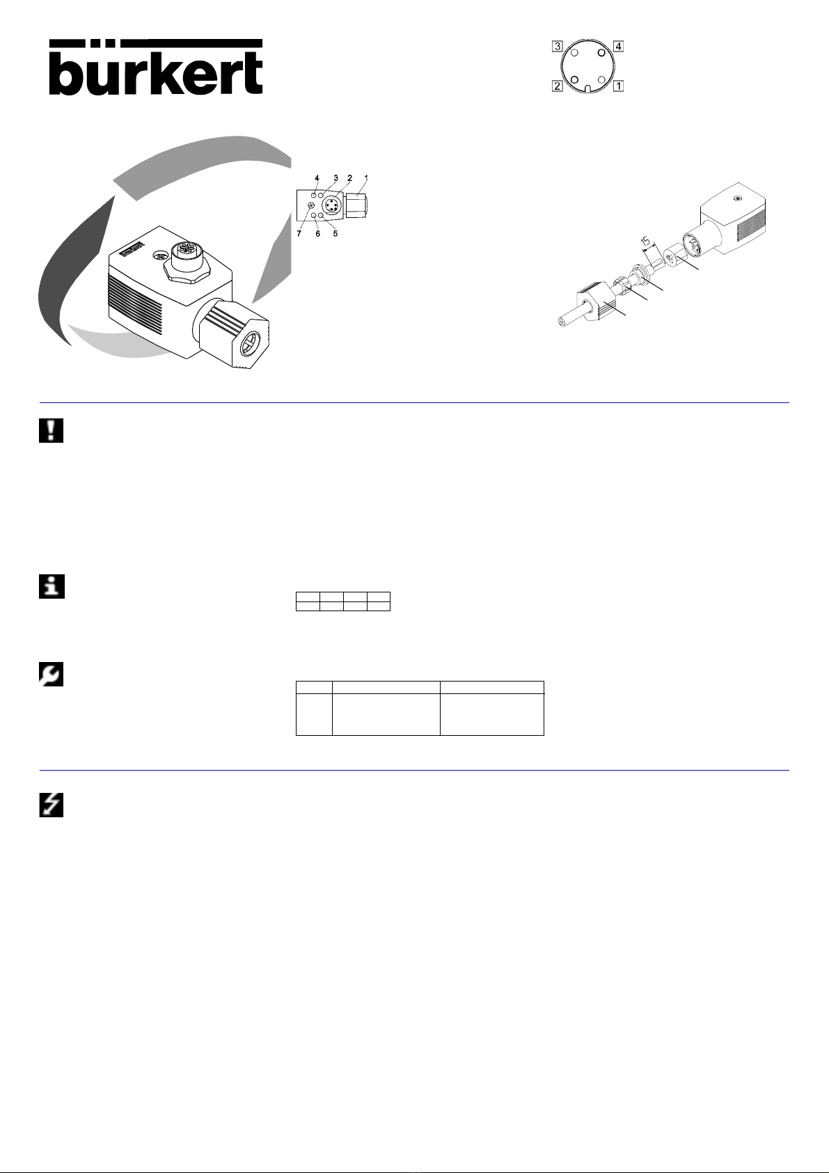
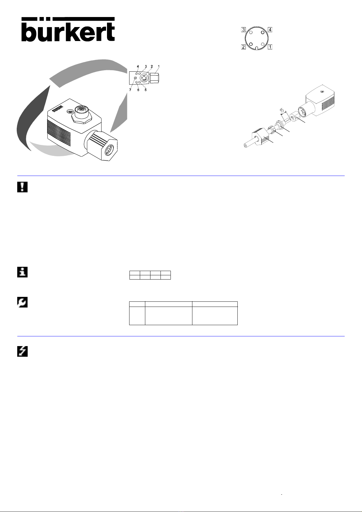
Fig. 1: Montaje de la caja de enchufe para aparatos eléctricos
Fig.2:Configuración enchufable M 12 zócalos de conexión
1 Abastecimiento de sensores + 24 D
2 Entrada de sensor 2
3 GND
4 Entrada de sensor1
Fig.3: Montaje de la caja de enchufe para aparatos eléctricos a la técnica
QUICKON
4
3
2
1
1 Conexión QUICKON de dos polos
2 Zócalo de conexión M12 entradas 1)
3 Entrada LED 2 (amarilla) 1)
conectado conectado
desconectado desconectado
4 Entrada LED 1 (amarilla) 1)
conectado conectado
desconectado desconectado
5 Bus LED (amarilla)
desconectado power off
on OK
parpadea dirección de esclavo = 0
6 Indicación del estado salida LED (verde)
conectado conectado
desconectado desconectado
7 Tornillo de fijación
ESTIMADO CLIENTE
Enhorabuena por la compra de este aparato Bürkert! Antes de la
instalación del aparato y por su propia seguridad, lea atentamente
estas Instrucciones de servicio.Su establecimiento competente
Bürkert le aclarará gustosamente toda clase de preguntas al
respecto.
Se ruega observar las indicaciones contenidas en estas
Instrucciones de servicio así como las condiciones de uso y
datos admisibles especificados en las hoja de servicio de las
válvulas magnéticas así como de la caja de enchufe para aparatos
eléctricos del tipo 2510 / 2511 Interface AS, de modo que el aparato
funcione impecablemente y permanezca durante largo tiempo apto
para el empleo.
• Para la planificación y operación del aparato, atenerse a las reglas
generales de la técnica!
• Las intervenciones solamente deben llevarse a cabo por parte de
personal especialista y con las herramientas adecuadas!
• Tomar las medidas apropiadas para excluir accionamientos no
intencionados o perjuicios inadmisibles!
• Prestar atención a que en sistemas que se encuentran bajo presión
no deben desconectarse conducciones y válvulas!
• La inobservancia de estas indicaciones así como las intervencio-nes
inadmisibles en el aparato suponen la declinación por nues-tra parte
de toda clase de responsabilidad, además de la extin-ción de la
garantía de los aparatos y de las piezas de accesorios!
La caja de enchufe para aparatos eléctricos del tipo 2510/2511
Interface AS sirve para el mando de bobinas de corriente conti-
nua con potencias ≤5V, sin abastecimiento externo de tensión.
• Función de unidad vigilante;INDICACION:En ausencia de tráfico de
datos, se repone la salida tras 50 - 100 ms.
• Conexión de dos sensores en la boca de conexión 12 (caja de
enchufe para aparatos eléctricos con entradas de confirmación)
- Encajar anillo de empalme (4);
ATENCION:plaridad: 1 = Bus+ 2 = Bus-
- Cortar ras con ras los extremos de conductores
- Girar rígidamente la atornilladura
• Introducir el tornillo cilíndrico por la caja de enchufe para aparatos
eléctricos
• Enchufar la junta de plana de estanqueidad en las conexiones de
enchufe del aparato
• Enchufar la caja de enchufe para aparatos eléctricos
• Asegure la caja de enchufe para aparatos eléctricos con el tornillo
cilíndrico (par máx.de apriete 1 Nm)
ATENCION! Observar que la junta de estanqueidad esté
impecablemente asentada antes de la atornilladura de la caja de
enchufe para aparatos eléctricos con la válvula magnética!
DATOS DE PROGRAMACIÓN
I/O configuration B hex ( 1 salida, 2 entradas)
Código ID F hex (para configuración véase abajo
Dirección previamente ajustada 0
Configuración del registro de datos
D3 D2 D1 D0
IN 11) IN 21) - OUT
Caja de enchufe para aparatos eléctricos con entradas de
confirmación
• En las bocas de conexión M 12 pueden conectarse 2 sensors con
un distribuidorY (véase figura 2)
ESPANOL
Antes de proceder a intervenciones en el sistema, desconectar
siempre la tensión de la caja de enchufe para aparatos eléctri-
cos del tipo 2510 / 2511 Interface AS! Typo Entradas de confirmación N° de pedido
2510 No 139 202 G
2510 Si 140 069 J
2511 No 140 071 C
2511 Si 140 070 P
Tabla 1: Datos de pedido
MONTAJE / PUESTA EN SERVICIO
• Cerrar la línea circular (2x 0.75 - 1.5 mm2) con arreglo al plan de
conexión (figura 3)
- Retirar cerca de 15 mm de recubrimiento de la conducción
- Montar por deslizamiento tuerca de unión (1), casquillo de
apriete (2) y junta de estanqueidad (3)
Tensión de línea según especificación 29.5..31.6 VDC
Consumo de corriente sin válvula y sensores 7 mA
Consumo de corriente total máx.280 mA
Conexión de bus
Conexión interface AS Técnica QUICKON, PG11
Sección de línea Línea circular 2 x 0.75 - 1.5 mm2
Capacidad de dirección programable Mín.15 direccionamiento
Salida
Potencia de conmutación / Tensión máx.5 W / 24V ± 10%
Corriente máx. 205mA, resistente al circuito
Función de unidad vigilante Integrada
Caja de enchufe para aparatos eléctricos del tipo 2510 para conexiones
enchufables (DIN 43650 forma C)
Caja de enchufe para aparatos eléctricos del tipo 2511 para conexiones
enchufables (DIN 43650 forma A)
Entradas
Modo de conexión de entrada PNP
Abastecimiento de sensores A través e interface AS
Tensión de abastecimiento sensor1) 24V ± 10%
Intensidad de corriente máx. 60mA, resistente al circuito
máxima admisible1)
Nivel de cableado señal ”1”1) ≥ 10V
Limit.de la corriente de entrada1) ≤6,5 mA
Corriente de entrada señal ”0” 1) ≤1,5 mA
DATOSTÉCNICOS
1) Con caja de enchufe para aparatos eléctricos con entradas de confirmación
Indicaciones de estado
Estado de conmutación LED verte
LED no / sí Desconectado / Conectado
Bus LED amarillo
LED no / sí Desenergizado / OK
LED centellea Dirección de esclavo = 0
Salidas 1) LED amarillo
LED no / sí Desconectado / Conectado
Caja
Modo de protección / Material IP 65 / PA
Dimensiones 32 x 32 x 65 mm
FijaciónType 2510 / 2511 Tornillo cilíndrico M2,5x 35 / M3 x 35
Temperatura de servicio 0 a +50 °C
Other manuals for 2510
4
This manual suits for next models
1
Table of contents
Languages:
Other Burkert Recording Equipment manuals