4
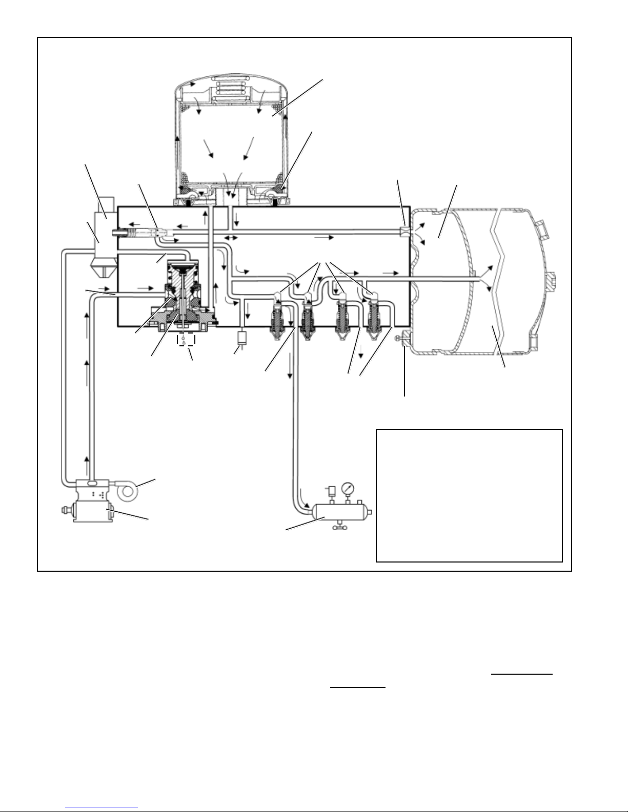
thesecondpressureprotectionvalve(B)opensandairwill
besuppliedto the secondaryreservoirandto theaccessory
pressure protection valves (C & D). (Note: there is no
external air hose feeding the secondary reservoir, instead
airissuppliedby a connectorpassingthroughthebulkhead
ofthepurge reservoirsectionofthereservoir.) Whentheair
pressureinthesecondaryreservoir reaches approximately
55 p.s.i. and 85 p.s.i. respectively, the two remaining
pressureprotectionvalves(C&D)willopenandsupply air
to the vehicle accessories.
The air dryer will remain in the charge cycle until the air
brakesystempressurebuilds to thegovernorcutoutsetting
of approximately 130 p.s.i.
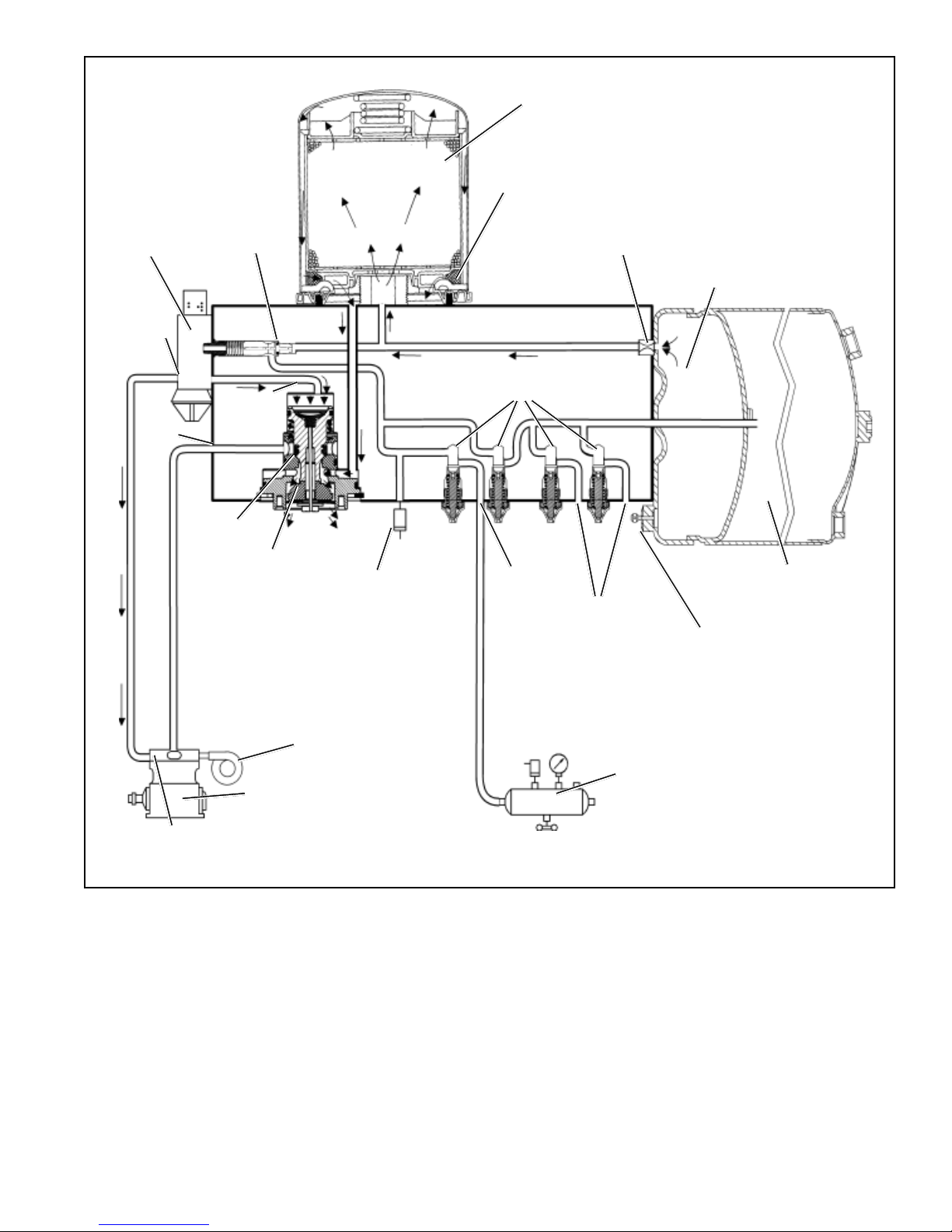
PURGE CYCLE (Refer to Figure 3.)
Whenairbrakesystempressure reaches the cutoutsetting
ofthegovernor,thegovernorunloads the compressor and
the purge cycle of the air dryer begins.
The governor unloads the compressor by allowing air
pressureto fill the line leading to the compressor unloader
mechanism - causing the delivery of compressed air to
theAD-IS®air dryer to be suspended.
Similarly, the governor also supplies air pressure to the
AD-IS®airdryerpurge controlchannel. TheAD-IS®airdryer
purgepiston moves down in response to this air pressure,
causingthepurgevalvetoopentotheatmosphere and the
turbo cutoff valve to close off the supply of air from the
compressor (this will be further discussed in the Turbo
Cutoff Feature section). Water and contaminants which
have collected in the purge valve base are expelled
immediately when the purge valve opens. Also, air which
wasflowingthroughthedesiccantcartridgechangesdirection
and begins to flow toward the open purge valve. Oil and
solidcontaminantscollectedbytheoilseparatorareremoved
byairflowing fromthepurgereservoirthroughthedesiccant
dryingbedtotheopenpurgevalve.
The initial purge and desiccant cartridge decompression
lasts only a few seconds and is evidenced by an audible
burst of air at theAD-IS®air dryer exhaust.
The actual reactivation of the desiccant drying bed begins
asdry air from the purge reservoir flows throughthe purge
orifice into the desiccant bed. Pressurized air from the
purge reservoir expands after passing through the purge
orifice; its pressure is lowered and its volume increased.
The flow of dry air through the drying bed reactivates the
desiccant material by removing the water vapor adhering
toit. Approximately 30 seconds are required forthe entire
contentsofthepurge reservoirofa standardAD-IS®airdryer
to flow through the desiccant drying bed.
Thedeliverycheckvalveassembly prevents airpressurein
the brake system from returning to the air dryer during the
purgecycle.Afterthepurgecycleiscomplete,theairdryer
is ready for the next charge cycle to begin.
TURBO CUTOFF FEATURE (Refer to Figure 3.)
The primary function of the turbo cutoff valve is to prevent
loss of engine turbocharger air pressure through the
AD-IS®air dryer in systems where the compressor intake
isconnected to the engine turbocharger.
Atthe onset of the purge cycle, the downward travel of the
purge piston is stopped when the turbo cutoff valve
(taperedportion of purge piston) contacts its mating metal
seatinthepurgevalvehousing. Withtheturbo cutoff valve
seated (closed position), air in the compressor discharge
lineandAD-IS®airdryerinletport cannot entertheairdryer.
In this manner the turbo cutoff effectively maintains turbo
chargerboost pressure to the engine.
PREVENTIVE MAINTENANCE
Important: Reviewthe warranty policy before performing
any intrusive maintenance procedures. An extended
warranty may be voided if intrusive maintenance is
performed during this period.
Because no two vehicles operate under identical
conditions, maintenance and maintenance intervals will
vary. Experience is a valuable guide in determining the
bestmaintenanceintervalforanyoneparticularoperation.
Every 900 operating hours, or 25,000 miles or three (3)
months:
1. Check for moisture in the air brake system by opening
reservoir drain valves and checking for presence of
water. If moisture is present, the desiccant cartridge
may require replacement; however, the following
conditions can also cause water accumulation and
should be considered before replacing the desiccant:
A. An outside air source has been used to charge the
system. This air does not pass through the drying
bed.
B. Air usage is exceptionally high and not normal.
This may be due to high air system leakage.
C. In areas where more than a 30 degree range of
temperature occurs in one day, small amounts of
water can temporarily accumulate in the air brake
system due to condensation. Under these
conditions, the presence of small amounts of
moisture is normal.
Note: A small amount of oil in the system is normal and
should not be considered as a reason to replace the
desiccantcartridge. Someoilatthedryerexhaustisnormal.
2. Visually check for physical damage such as chaffed or
broken air and electrical lines and broken or missing
parts.
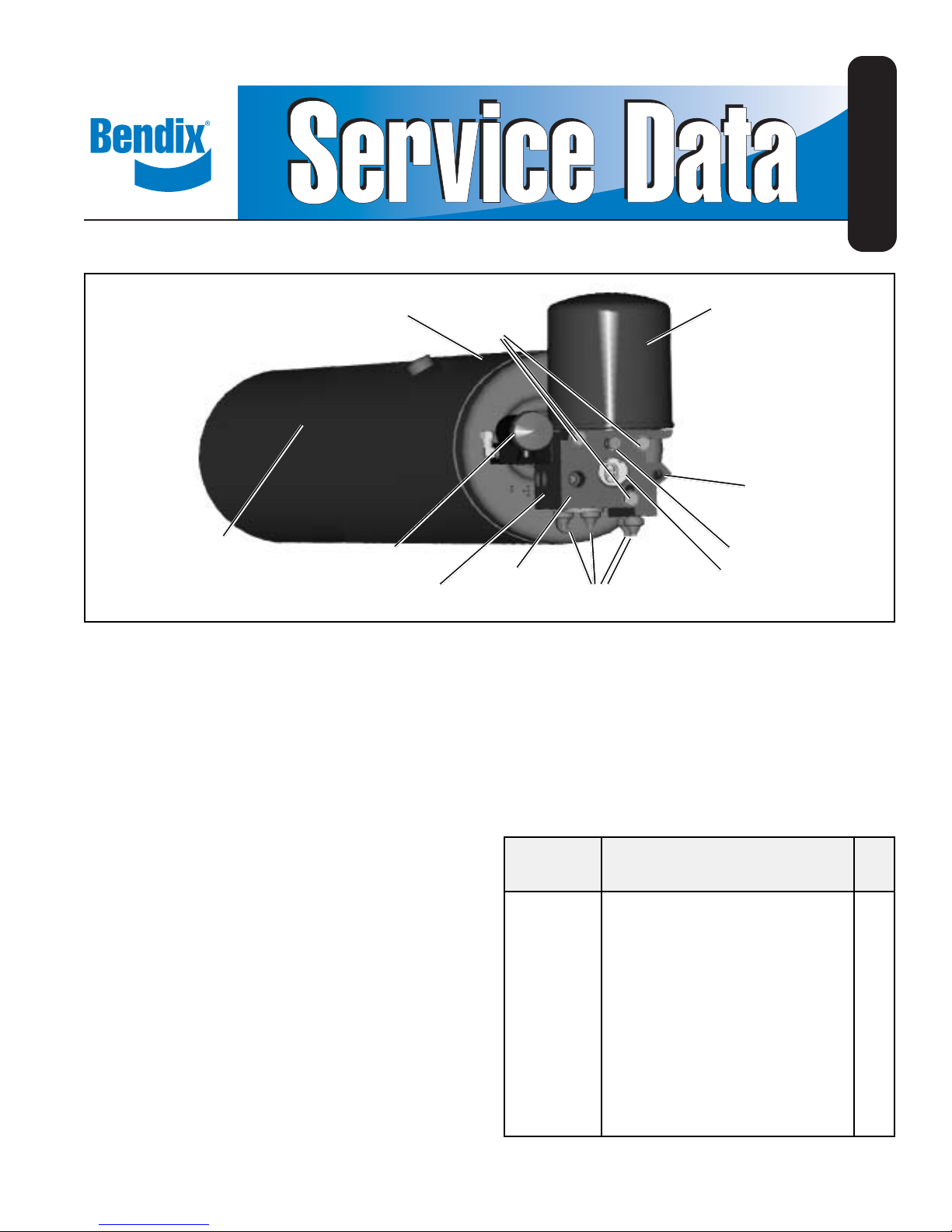
3. Check mounting bolts for tightness. See Figure 1.
Re-torqueto360-420inch pounds.


 installation instructions")