Hideaway Soft Close Series User manual

Step 2 - Secure the base
2a Use the Drilling Template 1 provided
(pictured below) to mark mounting
positions for Base Unit.
Pre-drilling instructions are shown on the
drilling template. Please follow instructions
given then move on to Step 2b.
Hideaway®Soft Close Range
Installation Instructions
60L Base Mounted
Laundry Hamper
PLEASE READ BEFORE YOU BEGIN
INSTALLATION INSTRUCTIONS
Important Installation Information:
AT ALL STAGES OF THE INSTALLATION ENSURE THE SPRING CARRIER ON THE
RUNNER IS ENGAGED!
Before you open your soft close runners, ensure the spring carriers are loaded. Failure to do so may cause damage to your runners.
Figure 1a - Demonstrates the spring
carrier in the engaged position. This is the
correct positioning.
Figure 1b - Demonstrates the spring carrier in an disengaged position. To move into
engaged position, move the white spring carrier along its runner until it clicks into location
demonstrated by arrow in Fig 1b. Alternatively, if discovered after installation is complete
then you may also try the following: push the drawer to the rmly closed position. Push the
disengaged side of the door rmly until you hear a click from the runner re-engaging. The
runner should now close fully under normal operation and be positioned as shown in Fig 1a.
Runner disengaged - incorrectRunner engaged - correct
FIG 1a - Runner Engaged FIG 1b - Runner Disengaged
Step 1 - Unpack Hideaway Bin
1a Remove the laundry hamper base from
packaging.
Remove the door bracket cover by
removing the M4 machine screw on right
and left side.
1b Remove the door mounting bracket
from the base by removing the M6 cap
screws using the hex key provided.
Leave the runners and runner support
connected with the base plate.
The base unit is now ready to be installed.
Use the Base Unit Drilling Installation
Template 1 provided.

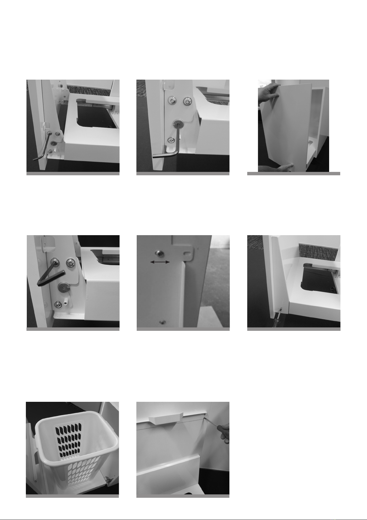
2b Install the base unit over the pre-drilled
mounting holes. Secure with 1x 16mm
screw at the front of each base side.
Drilling Template 1 pictured below.
NOTE: Remove template from cabinet
when pre-drilling is complete.
Step 3 - Door attachments
3a Use the Door Support Bracket and
Handle Support Drilling Template 2
(pictured below) to mark mounting
positions on the door fascia.
Pre-drilling instructions are shown on the
drilling template.
2c Secure with 1x 16mm screw at the
back of each base side.
3b Position the Door Support Bracket over
mounting holes and secure with 12mm
screws provided.
NOTE: Alternative mounting holes are
provided on the outside edge of the
door mounting bracket, for door panels
with centre inserts (prole doors). The
alternate mounting points do not need to
be used if the inner mounting holes are
used and vice versa.
2d Fully extend the Base Unit to ensure
the Base Unit opens and closes without
coming in to contact with cabinet sides.
Then fully extend again and secure the
remaining mounting points of both base
sides with 16mm screws provided.
3c Position the Handle Support Bracket
over the pre-drilled mounting holes and
secure with the 12mm screws provided.
Image below: Door panel with door
mounting bracket and handle support
bracket attached.
Use the Drilling Template 2 provided
(pictured below) to mark mounting positions
for Door Support Bracket and Handle
Support Bracket. Pre-drilling instructions
are shown on the Drilling Template 2.
Please follow instructions and move on to
Step 3b
NOTE: Remove template when completed.
Step 4 - Reattach door bracket
(now with door fascia attached)
4a Set the CAM adjustment in the
horizontal position, as indicated by the
arrow on the CAM.
Align and reattach the door mounting
bracket (now xed to the door fascia) to
the base unit as pictured.

5C. To make a horizontal adjustment:
The door panel may be moved sideways
or horizontally by loosening the mounting
screws in the door mounting bracket
sufciently to allow the required
movement. Retighten mounting screws
when the desired position is achieved.
Step 6 - Install the door cover
Install the cover for the door mounting
bracket by placing the cover over the door
mounting bracket and secure with the M4
Machine screws provided.
5B. To adjust the door pitch:
Push the door panel rmly at top or
bottom to make the door panel sit in the
correct position when closed.
Reopen the draw by pulling from the
bottom of door panel to ensure the correct
positioning is maintained.
Step 7 - Install Hamper and
Adjust the Handle Support
Bracket
7a Install the laundry hamper in to the
cutout provided and adjust the handle
support bracket, if required, to ensure the
support bracket provides support under
the handle lip of the laundry hamper.
Fully tighten all M6 Cap screws to
maintain a permanent door position.
NOTE: If the door adjustment is not
holding then tighten M6 Cap screws
further and repeat steps 5a and 5b.
7b The handle support bracket position
may be altered up or down by loosening
the mounting screws and altering the
bracket position.
Retighten screws when the desired
position is achieved.
Step 5 - Door adjustment
5A. To adjust the door height (up or
down):
Rotate the CAM Adjustor up or down
using the hex key.
YOUR INSTALLATION
IS COMPLETE!
4b Insert the M6 Cap screws. These
should be tightened with hex key to a
point that holds the door in place but will
allow some movement for adjustment
purposes.

Need more info?
NEW ZEALAND
Phone 09 426 7456 [email protected] www.hideawaybins.co.nz
AUSTRALIA
Freephone 1800 042 642 [email protected] www.hideawaybins.com.au
CONTACT PARTS REFERENCE
NZ Patent Application No. 704815
16 x 12mm screws 6 x M6 cap screws
Hex Key
18 x 16mm screws 2 x M4 machine screws
Other Hideaway Laundry Accessories manuals