manuals.online logo
Brands
  1. Home
  2. •
  3. Brands
  4. •
  5. BENDIX
  6. •
  7. Switch
  8. •
  9. BENDIX SL-5-DS-2 SWITCH AND CHECK VALVE User manual

BENDIX SL-5-DS-2 SWITCH AND CHECK VALVE User manual

1
Bendix®SL-5™Stop Light Switch & Bendix®DS-2™Combined
Stop Light Switch & Double Check Valve
SD-06-1804
DESCRIPTION
TheBendix®SL-5™stoplightswitchisanelectro-pneumatic
5psinon-groundedswitch that operates inconjunctionwith
thebrake valveand stop lights by completing the electrical
circuit and lighting the stop lights when a brake application
is made.
The DS-2™combined stop light switch and double check
valve, as the name implies, combines a SL-5™stop light
switch with a DC-4™double check valve to perform the
function of both. It operates in conjunction with the brake
valveandhandcontrolvalveby directing the flow ofairfrom
whicheverdeliversthehigherpressureintoacommondelivery
lineand to thestop light switch,closing theelectrical circuit
to the stop lamps.
The stop light switch can be used with either 12 or 24 volt
systems.
The stoplight switch is not a serviceable item; and if found
defectiveineitherdevice,thecompleteunitmustbereplaced.
TheshuttlevalveintheDS-2™valve isserviceableandmay
bereplaced.
BoththeSL-5™switchandtheDS-2™valvehavebeentested
andmeet therequirements ofFMVSS 121.
OPERATION
Thestop switch mechanismis identical inthe SL-5™switch
andtheDS-2™valve.
When a brake application is made, air pressure from the
brakevalve enters the cavity belowthe diaphragm.The air
pressure below the diaphragm moves the piston until it
contactstheleafspring.Theleafspringtravelspastafulcrum
at which point the leaf springs snaps a shorting bar which
mateswiththecontact strips. Thestoplightelectrical circuit
DS-2™
VALVE SL-5™
STOP
LIGHT
SWITCH
FIGURE 1 - DS-2™COMBINED STOP LIGHTSWITCH & DOUBLE CHECK VALVE SECTIONAL
RIVET
INLET PORT INLET
PORT
CONTACT
STRIP
FULCRUM
SHORTING
BAR
TERMINAL
OUTLET PORT
LEAF
SPRING
PISTON
DIAPHRAGM
SHUTTLE
VALVE
(CHECK
VALVE)
2
is completed, lighting the stop lights before the brake
applicationpressures reach 6 psi.
Thesnap action spring design minimizes arcing.
Thedoublecheck valve isactivatedby air beingintroduced
througheitherofthetwo(2)inletports.Thegreater pressure
pushestheshuttle along itsguides and closestheopposite
inlet port. The air is then directed out the common delivery
line and to the stop light switch.
PREVENTIVE MAINTENANCE
Important: Review the Bendix Warranty Policy before
performinganyintrusivemaintenanceprocedures.Awarranty
maybevoidedif intrusive maintenanceisperformedduring
thewarrantyperiod.
No two vehicles operate under identical conditions; as a
result, maintenance intervals may vary. Experience is a
valuableguideindeterminingthebestmaintenanceinterval
for air brake system components. At a minimum, the
DS-2™/SL-5™valve should be inspected every6 months or
1500 operating hours, whichever comes first, for proper
operation and electrical connections. Should the DS-2™/
SL-5™valvenot meet the elements ofthe operationaltests
notedin this document, further investigationand service of
thevalvemayberequired.
OPERATING AND LEAKAGE TEST
1. Installanaccurateairgauge in the serviceline(orbrake
chamber).Applybrakevalvegradually.Stoplampsshould
lightat6psiorlessandgo out after the brakeapplication
is released. This checks the electrical function of the
stop light switch in either the SL-5™switch or DS-2™
valve.
2. (DS-2™valve only) Apply the foot valve and coat the
exhaustportofthehandvalve(orotheralternatesource).
Reverse the above, applying the hand valve or other
alternate source and coat the exhaust port of the foot
valve. In either mode a leakage of not more than a 1”
bubble in 5 seconds is permissible.
3. (SL-5™switch or DS-2™valve) When pressurized, no
leakageispermittedfromthebody ofthevalveorswitch.
If the SL-5™switch or DS-2™valve does not function as
describedaboveorifleakageisexcessive,thevalveorswitch
should be replaced with a new unit or in the case of the
doublecheckportionoftheDS-2™valverepairedwithgenuine
Bendix parts.
REMOVINGAND INSTALLING
REMOVING
1. Blockvehiclewheelsorhold bymeansotherthanvehicle
servicebrakes.
2. Disconnectelectricalconnectionsfromterminalscrews.
3. (SL-5™switch) Remove the switch using a wrench on
the hex portion of the body.
4. (DS-2™valve)DisconnectairlinesandremovetheDS-2™
valve.
INSTALLING
1. Replace the SL-5™switch or DS-2™valve in the port
from which it was removed. Do not install with the
terminalspointingdown.
2. Secureelectrical connections.
3. Reinstallair line connectionsto DS-2™valve.
DISASSEMBLY(Double Check Valve)
1. Removethree cap screwsand cap.
2. Removeo-ringsealfromcap.
3. Removeshuttlevalve.
CLEANINGANDINSPECTION
1. Blow dust or other foreign material out of body. Do not
immersein cleaning fluid.
2. Inspect shuttle valve and o-rings for excessive wear or
deterioration.Inspect valve seatsfor nicks orburrs.
Replace all parts that were discarded and any parts not
founds to be serviceable during inspection, using only
genuineBendixreplacement parts.
ASSEMBLY
BeforeassemblingtheDS-2™doublecheckvalve, lubricate
allo-rings and o-ringgrooveswith Bendix siliconelubricant
(Pc.No.291126) orequivalent.
NOTE: When using pipe thread sealant during assembly
and installation, take particular care to prevent the
sealant from entering the valve itself. Apply the
sealantbeginningwiththesecond thread back from
theend.
TEST
Repeat“OperatingandLeakageTest”.
WARNING! PLEASE READ AND FOLLOW
THESE INSTRUCTIONS TO AVOID
PERSONAL INJURYOR DEATH:
When working on or around a vehicle, the following
general precautions should be observed at all times.
1. Park the vehicle on a level surface, apply the
parking brakes, and always block the wheels.
Always wear safety glasses.
2. Stop the engine and remove ignition key when
working under or around the vehicle. When
working in the engine compartment, the engine
should be shut off and the ignition key should be
removed. Where circumstances require that the
enginebeinoperation,EXTREMECAUTIONshould
be used to prevent personal injury resulting from
contact with moving, rotating, leaking, heated or
electrically charged components.
3. Do not attempt to install, remove, disassemble or
assemble a component until you have read and
thoroughly understand the recommended
procedures. Useonlythe proper tools and observe
all precautions pertaining to use of those tools.
3
4. If the work is being performed on the vehicle’s air
brake system, or any auxiliary pressurized air
systems,makecertainto drain the airpressurefrom
all reservoirs before beginning ANY work on the
vehicle. If the vehicle is equipped with an AD-IS®
air dryer system or a dryer reservoir module, be
sure to drain the purge reservoir.
5. Following the vehicle manufacturer’s
recommendedprocedures,deactivatetheelectrical
system in a manner that safely removes all
electrical power from the vehicle.
6. Never exceed manufacturer’s recommended
pressures.
7. Never connect or disconnect a hose or line
containing pressure; it may whip. Never remove a
component or plug unless you are certain all
system pressure has been depleted.
8. Use only genuine Bendix®replacement parts,
components and kits. Replacement hardware,
tubing, hose, fittings, etc. must be of equivalent
size, type and strength as original equipment and
be designed specifically for such applications and
systems.
9. Components with stripped threads or damaged
parts should be replaced rather than repaired. Do
not attempt repairs requiring machining or welding
unless specifically stated and approved by the
vehicle and component manufacturer.
10. Prior to returning the vehicle to service, make
certainallcomponentsandsystemsarerestoredto
their proper operating condition.
11. For vehicles with Antilock Traction Control (ATC),
the ATC function must be disabled (ATC indicator
lampshoud beON)prior toperforminganyvehicle
maintenance where one or more wheels on a drive
axle are lifted off the ground and moving.
4BW1594 © 2006 Bendix Commercial Vehicle Systems LLC All rights reserved. 7/2006 Printed in U.S.A.

This manual suits for next models

2

Other BENDIX Switch manuals

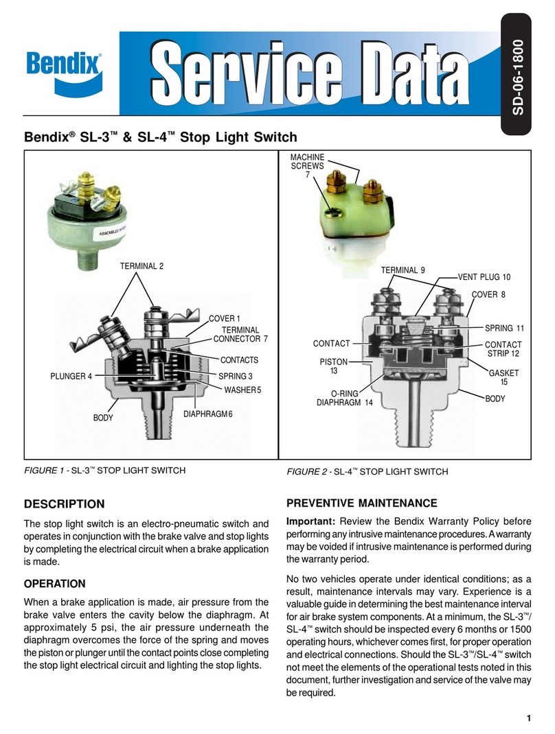
BENDIX SL-3-SL-4 STOP LIGHT SWITCH User manual

BENDIX

BENDIX SL-3-SL-4 STOP LIGHT SWITCH User manual

BENDIX TE-1 TRAILER EMERGENCY STOP LIGHT User manual

BENDIX

BENDIX TE-1 TRAILER EMERGENCY STOP LIGHT User manual

Popular Switch manuals by other brands

Pico Macom TSMS-5 Installation and operation manual

Pico Macom

Pico Macom TSMS-5 Installation and operation manual

Hall Research Technologies KVM-HDU-4 user manual

Hall Research Technologies

Hall Research Technologies KVM-HDU-4 user manual

Maxim Integrated MAX4684 Series General description

Maxim Integrated

Maxim Integrated MAX4684 Series General description

Cisco Nexus 7710 Site Preparation and Hardware Installation Guide

Cisco

Cisco Nexus 7710 Site Preparation and Hardware Installation Guide

Linksys EG008W - Instant Gigabit Workgroup Switch user guide

Linksys

Linksys EG008W - Instant Gigabit Workgroup Switch user guide

Broadcast Tools ROS Installation and operation manual

Broadcast Tools

Broadcast Tools ROS Installation and operation manual

Murphy VS2 Series Specification sheet

Murphy

Murphy VS2 Series Specification sheet

LevelOne GEL-2060 Configuration Commands

LevelOne

LevelOne GEL-2060 Configuration Commands

N-audio Two Amps To Cabinet user manual

N-audio

N-audio Two Amps To Cabinet user manual

Alloy ESM-24T02M Quick installation guide

Alloy

Alloy ESM-24T02M Quick installation guide

Kopec USB-210C user manual

Kopec

Kopec USB-210C user manual

Nortek GoControl WS15Z5-1 manual

Nortek

Nortek GoControl WS15Z5-1 manual

ALLEN & HEATH PL-9 user guide

ALLEN & HEATH

ALLEN & HEATH PL-9 user guide

Rompa 15896 operating instructions

Rompa

Rompa 15896 operating instructions

Surecom EP-710CG user manual

Surecom

Surecom EP-710CG user manual

Siemens SIMATIC NET RUGGEDCOM RST2228P installation manual

Siemens

Siemens SIMATIC NET RUGGEDCOM RST2228P installation manual

Network Technologies KEEMUX-Px Installation and operation manual

Network Technologies

Network Technologies KEEMUX-Px Installation and operation manual

Electro Cam PLUS PS-5000 Series Programming & installation manual

Electro Cam

Electro Cam PLUS PS-5000 Series Programming & installation manual

manuals.online logo
manuals.online logoBrands
  • About & Mission
  • Contact us
  • Privacy Policy
  • Terms and Conditions

Copyright 2025 Manuals.Online. All Rights Reserved.