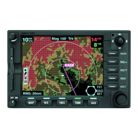
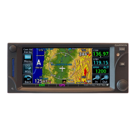
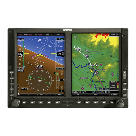
BENDIXKing KSN 8 Series User manual

© Honeywell International Inc. Do not copy without express permission of Honeywell.
Honeywell International, Inc.
9201-B San Mateo Blvd N.E.
Albuquerque, New Mexico 87113
U.S.A.
Telephone: 855-250-7027 (Toll Free U.S.A./Canada)
Telephone: 602-365-7027 (International Direct)
KSN 780/8XX/900 AERONAV AML STC
INSTALLATION MANUAL FOR HELICOPTERS
Document P/N 89000046-014 Rev 0
November 2019
Export Control
This document contains technical data and is subject to U.S. export regulations. These
commodities,
technology, or software were exported from the United States in accordance
with the export administration regulations. Diversion contrary to U.S. law is prohibited.
ECCN: 7E994

Blank Page

89000046-014 KSN 780/8XX/900 AeroNav AML STC Installation Manual for Helicopters
Rev 0 Page T-3
© Honeywell International Inc. Do not copy without express permission of Honeywell.
Warranty/Liability Advisory
WARNING: HONEYWELL ASSUMES NO RESPONSIBILITY FOR ANY HONEYWELL EQUIPMENT WHICH
IS
NOT MAINTAINED AND/OR REPAIRED IN ACCORDANCE WITH HONEYWELL’S PUBLISHED
INSTRUCTIONS AND/OR HONEYWELL’S FAA/SFAR 36 REPAIR AUTHORIZATION. NEITHER DOES
HONEYWELLASSUMERESPONSIBILITYFORSPECIALTOOLSANDTESTEQUIPMENTFABRICATEDBY
COMPANIES OTHER THAN HONEYWELL.
WARNING: INCORRECTLY REPAIRED COMPONENTS CAN AFFECT AIRWORTHINESS OR DECREASE
THE
LIFE OF THE COMPONENTS. INCORRECTLY FABRICATED SPECIAL TOOLING OR TEST
EQUIPMENT CAN
RESULT IN DAMAGE TO THE PRODUCT COMPONENTS OR GIVE UNSATISFACTORY
RESULTS.
Copyright – Notice
Honeywell is a registered trademark of Honeywell International Inc.
All other marks are owned by their respective companies.
Our products are under continuous research and development. Any information may therefore
be changed
without prior notice. Honeywell reserves the right to make improvements or
changes in the product described
in this manual at any time without notice. While reasonable
efforts have been made in the preparation of this
document to assure its accuracy, Honeywell
assumes no liability resulting from any errors or omissions in this
document, or from the use of
the information contained herein.
Honeywell Aerospace Online Technical Publications Website
Go to the Honeywell Online Technical Publications Website at
https://myaerospace.honeywell.com/.
1. To download or view publications online
2. To tell BendixKing of a possible data error in a publication.
3. Changes to this manual are provided to users who have registered via the website to
receive updates.
BendixKing Customer Support
If you need to speak to personnel about Technical matters, the BendixKing Customer
Support team provides 24/7 customer service.
•Telephone: 855-250-7027 (Toll Free U.S.A./Canada)
•Telephone: 602-365-7027 (International)
•Website: www.bendixking.com
•Email: techsuppo[email protected]

89000046-014 KSN 780/8XX/900 AeroNav AML STC Installation Manual for Helicopters
Rev 0 Page T-4
© Honeywell International Inc. Do not copy without express permission of Honeywell.
RECORD OF REVISIONS
NOTE: The revision level for every page of this document will be updated during the revision
process. A list of effective pages is, therefore, not required.
Revision
Revision Date
Description
0
12 November 2019
Initial Release

89000046-014 KSN 780/8XX/900 AeroNav AML STC Installation Manual for Helicopters
Rev 0 Page T-5
© Honeywell International Inc. Do not copy without express permission of Honeywell.
The content contained herein is proprietary to the manufacture. The applicable STCs are
associated with both the BendixKing and Manufacture part numbers cross-referenced in the
table below.
BENDIXKING/MANUFACTURE PART NUMBER CROSS-REFERENCE
BendixKing
Part Number
Manufacture
Part Number
Product Description
89000039-003 850-00182-700 AeroNav 900,10W, GPS/Nav/Com/WiFi/BT/FLTA/SVS/--Black
89000039-004 850-00182-701 AeroNav 900, 10W, GPS/Nav/Com/WiFi/BT/FLTA/SVS//RS170
89000039-007 850-00188-002 AeroNav 880 & 900 Install Kit, Fixed Wing (Tray, Backplate,
89000039-009 850-00188-003 AeroNav 880 & 900
Install Kit, Helicopter (Tray, Backplate, Connectors)
89000041-002 850-00179-700 AeroNav 800, 10W, GPS/Nav/Com/WiFi/BT/FLTA/SVS--Black
89000041-005 850-00184-002 AeroNav 780 & 800 Install Kit, Fixed Wing (Tray, Backplate,
89000041-007 850-00184-003
AeroNav 780 & 800 Install Kit, Helicopter (Tray, Backplate, Connectors)
89000041-009 850-00182-710 AeroNav 880, GPS/WiFi/BT/FLTA/SVS/--Black
89000041-010 850-00182-711 AeroNav 880, GPS/WiFi/BT/FLTA/SVS//RS170
89000045-003 850-00179-710 AeroNav 780, GPS(ONLY)/WiFi/BT/FLTA/SVS—Black
89000046-002 500-00210-000 16W VHF Enablement Factory Activation
89000046-003 500-00232-000 Radar (RDR 2000/RDR 2100) Enablement Factory Activation
89000046-004 500-00258-000 Helicopter Enablement Factory Activation
89000046-005 500-00277-000 GPS Legacy Avionics Support (GLAS) LPV Enablement Factory
89000046-006 500-00210-002 16W VHF Enablement Field Activation Coupon
89000046-007 500-00232-002 Radar (RDR 2000/RDR 2100) Enablement Field Activation Coupon
89000046-008 500-00258-002 Helicopter Enablement Field Activation Coupon
89000046-009 500-00277-002 GPS Legacy Avionics Support (GLAS) LPV Enablement Field Activation
89000046-010 850-00217-001 Antenna, GPS TSO-C190, Hemispherical, TNC Female, White
89000046-011 820-00101-001 Byteflight Cable (20')

89000046-014 KSN 780/8XX/900 AeroNav AML STC Installation Manual for Helicopters
Rev 0 Page T-6
© Honeywell International Inc. Do not copy without express permission of Honeywell.
Table of Contents
1. General Information...................................................................1-1
1.1 Introduction ...................................................................................................................... 1-1
1.2 Applicability....................................................................................................................... 1-1
1.3 Unit Modifications............................................................................................................. 1-3
1.4 Technical Specifications .................................................................................................... 1-3
1.4.1 AeroNav 880/900 Specifications................................................................................... 1-3
1.4.2 AeroNav 780/800 Specifications................................................................................... 1-2
1.5 Power Requirements......................................................................................................... 1-5
1.6 Regulatory Compliance ..................................................................................................... 1-5
1.6.1 Applicable TSOs............................................................................................................. 1-5
1.6.2 TSO Deviations .............................................................................................................. 1-7
1.6.3 Non-TSO Functions ....................................................................................................... 1-8
1.6.4 Partial TSO Functions .................................................................................................... 1-9
1.6.5 Open Problem Report................................................................................................... 1-9
1.7 Software and Hardware Design Assurance Levels ............................................................ 1-9
1.8 Environmental Qualification Forms................................................................................. 1-10
1.9 Databases ........................................................................................................................ 1-10
1.10 Fault Detection and Exclusion (FDE)................................................................................ 1-10
1.11 Part 27 Helicopter STC Approved Model List .................................................................. 1-12
1.12 BendixKing Supplied Material ......................................................................................... 1-13
1.12.1 Product Ship Kits..................................................................................................... 1-13
1.12.2 Optional Ship Kits ................................................................................................... 1-13
1.13 Materials Required but not Supplied .............................................................................. 1-14
2. Installation Considerations.........................................................2-1
2.1 Plug & Play Considerations................................................................................................ 2-1
2.2 Optional Installation Features........................................................................................... 2-2
2.3 AeroNav XXX Interfaces..................................................................................................... 2-3
2.4 Minimum System Configuration for VFR........................................................................... 2-8
2.4.1 VFR Installation ............................................................................................................. 2-8
2.5 Pre-Installation Checklist................................................................................................... 2-9

89000046-014 KSN 780/8XX/900 AeroNav AML STC Installation Manual for Helicopters
Rev 0 Page T-7
© Honeywell International Inc. Do not copy without express permission of Honeywell.
3. Antenna Installation...................................................................3-1
3.1 Antenna Bonding............................................................................................................... 3-1
3.2 Antenna Environmental Qualifications ............................................................................. 3-1
3.3 GPS Antenna...................................................................................................................... 3-1
3.3.1 GPS Antenna Location................................................................................................... 3-2
3.3.2 GPS Antenna Bonding ................................................................................................... 3-5
3.3.3 GPS Antenna Cable ....................................................................................................... 3-5
3.3.4 GPS Coaxial Cable Connector........................................................................................ 3-5
3.3.5 Approved GPS Antennas............................................................................................... 3-5
3.3.6 GPS Interference........................................................................................................... 3-6
3.3.7 Ground Plane ................................................................................................................ 3-6
3.3.8 Dual AeroNav XXX Installations .................................................................................... 3-6
3.3.9 Anti-Ice Protection........................................................................................................ 3-6
3.4 VHF Communication Antenna........................................................................................... 3-6
3.4.1 Antenna Environmental Qualifications......................................................................... 3-6
3.4.2 VHF Communication Cable ........................................................................................... 3-6
3.4.3 VHF Coaxial Cable Connector........................................................................................ 3-6
3.4.4 Voltage Standing Wave Ratio........................................................................................ 3-7
3.4.5 VHF Antenna ................................................................................................................. 3-7
3.4.6 Antenna Ground Plane.................................................................................................. 3-7
3.5 Navigation Antenna........................................................................................................... 3-7
3.5.1 VOR/LOC Antenna......................................................................................................... 3-7
3.5.2 Navigation Coaxial Cable............................................................................................... 3-7
3.5.3 Navigation Coaxial Cable Connector............................................................................. 3-7
3.5.4 Diplexer......................................................................................................................... 3-7
3.6 Glideslope Antenna ........................................................................................................... 3-7
3.6.1 Glideslope ..................................................................................................................... 3-7
4. Electrical Installation ..................................................................4-1
4.1 Wire Type .......................................................................................................................... 4-1
4.2 Wire and Connector Identification.................................................................................... 4-1
4.3 Wire Routing ..................................................................................................................... 4-1

89000046-014 KSN 780/8XX/900 AeroNav AML STC Installation Manual for Helicopters
Rev 0 Page T-8
© Honeywell International Inc. Do not copy without express permission of Honeywell.
4.4 Shield Grounds .................................................................................................................. 4-1
4.5 Wire Harness Overbraid.................................................................................................... 4-1
4.5.1 Existing Equipment ....................................................................................................... 4-1
4.5.2 Severe Lightning Transient Environment...................................................................... 4-1
4.5.3 Copper Overbraid Installation....................................................................................... 4-2
4.6 AeroNav XXX Connectors .................................................................................................. 4-2
4.7 Byteflight Digital Data Bus Consideration – Dual AeroNav Installations........................... 4-2
4.7.1 Databus Wiring - Replacement Installations................................................................. 4-2
4.7.2 Databus Wiring – New Installations.............................................................................. 4-3
4.8 Circuit Protection .............................................................................................................. 4-3
4.9 Power Distribution ............................................................................................................ 4-3
4.10 Electrical Load Analysis ..................................................................................................... 4-4
4.11 Low Power Behaviors ........................................................................................................ 4-4
5. Mechanical Installation ..............................................................5-1
5.1 Equipment Location – New Installations........................................................................... 5-1
5.1.1 Course Deviation Indicator ........................................................................................... 5-1
5.1.2 Instrument Panel Cutout............................................................................................... 5-1
5.1.3 Requirements for Tray Installation ............................................................................... 5-1
5.2 Equipment Location - Replacement Unit .......................................................................... 5-2
5.3 Angle of Regard ................................................................................................................. 5-2
5.4 Unit Installation/Removal ................................................................................................. 5-2
5.5 Internal Cooling ................................................................................................................. 5-2
5.6 External Cooling ................................................................................................................ 5-2
5.7 Electrical Bonding.............................................................................................................. 5-3
5.8 Weight and Balance .......................................................................................................... 5-3
5.9 Compass Safe Distance...................................................................................................... 5-3
6. System Installation .....................................................................6-1
6.1 Pin Function List ................................................................................................................ 6-1
6.1.1 P1001 Main Connector ................................................................................................. 6-1
6.1.2 P1002 Communication Connector................................................................................ 6-3
6.1.3 P1006 Navigation Connector ........................................................................................ 6-4

89000046-014 KSN 780/8XX/900 AeroNav AML STC Installation Manual for Helicopters
Rev 0 Page T-9
© Honeywell International Inc. Do not copy without express permission of Honeywell.
6.1.4 P1050 Additional I/O Connector................................................................................... 6-5
6.1.5 Altitude Gray Code........................................................................................................ 6-6
6.1.6 Heading Input ............................................................................................................... 6-7
6.1.7 Main Course Deviation Indicator Output...................................................................... 6-7
6.1.8 Serial Data................................................................................................................... 6-10
6.1.9 ARINC 429 ................................................................................................................... 6-10
6.1.10 ARINC 453............................................................................................................... 6-13
6.1.11 RS170 Video............................................................................................................ 6-13
6.1.12 Com/VOR/ILS Audio Electrical Characteristics ....................................................... 6-14
6.1.13 VOR/ILS Indicator Electrical Characteristics ........................................................... 6-15
6.1.14 DME Tuning ............................................................................................................ 6-15
6.2 Bezel Lighting .................................................................................................................. 6-16
6.3 Traffic System.................................................................................................................. 6-17
6.4 Lightning Detection System............................................................................................. 6-17
6.5 Datalink Weather ............................................................................................................ 6-18
6.6 Audio Panels.................................................................................................................... 6-18
6.7 GAD 42 ............................................................................................................................ 6-19
6.8 Air Data System Sources.................................................................................................. 6-19
6.9 Heading System Sources ................................................................................................. 6-20
6.10 Multifunction Displays .................................................................................................... 6-21
6.11 ADS-B Transponder/UAT Output .................................................................................... 6-21
6.12 Video Input...................................................................................................................... 6-25
6.13 Radar Display and Control............................................................................................... 6-25
6.14 Weight on Wheels (Collective Switch) Input................................................................... 6-25
7. Configuration and Checkout .......................................................7-1
7.1 Wiring Check ..................................................................................................................... 7-1
7.2 Mounting Check ................................................................................................................ 7-1
7.3 Chassis ID Setting .............................................................................................................. 7-1
7.4 Unit Installation................................................................................................................. 7-2
7.5 Configuration..................................................................................................................... 7-2
7.5.1 Maintenance Mode ...................................................................................................... 7-2
7.5.2 ARINC 429 Port Configuration (Page 1) ........................................................................ 7-3

89000046-014 KSN 780/8XX/900 AeroNav AML STC Installation Manual for Helicopters
Rev 0 Page T-10
© Honeywell International Inc. Do not copy without express permission of Honeywell.
7.5.3 RS-232 Port Configuration (Page 2) .............................................................................. 7-8
7.5.4 Main System Configuration (Page 3) .......................................................................... 7-12
7.5.5 Main Input Configuration (Page 4).............................................................................. 7-15
7.5.6 Main Lighting Configuration (Page 5) ......................................................................... 7-16
7.5.7 Main Discrete I/O (Page 6).......................................................................................... 7-20
7.5.8 Main CDI/OBS Config Page (Page 7) ........................................................................... 7-21
7.5.9 VOR/LOC/GS CDI (Page 8)........................................................................................... 7-24
7.5.10 VOR/LOC/GS ARINC 429 Configuration (Page 9) .................................................... 7-26
7.5.11 GPS Vertical Offset (Page 10) ................................................................................. 7-27
7.5.12 Main ARINC 429 Port 3 Configuration (Page 11) .................................................... 7-28
7.5.13 GDL Configuration Pages (Page 11) ........................................................................ 7-29
7.5.14 Remote XPDR Configuration (Page 12)................................................................... 7-30
7.5.15 WiFi Setup (Page 13) .............................................................................................. 7-30
7.5.16 Bluetooth Setup (Page 14)...................................................................................... 7-37
7.5.17 RDR2000 Radar Configuration (Page 16)................................................................ 7-38
7.5.18 Stormscope Test Page (Page 17) ............................................................................ 7-39
7.5.19 GAD 42 Configuration............................................................................................. 7-40
7.5.20 Other System Diagnostics Pages ............................................................................ 7-40
7.6 Checkout ......................................................................................................................... 7-42
7.6.1 Database Check........................................................................................................... 7-42
7.6.2 Airplane Flight Supplement Check.............................................................................. 7-42
7.6.3 Instructions for Continued Airworthiness................................................................... 7-42
7.6.4 Aircraft Weight and Balance ....................................................................................... 7-42
7.6.5 Electrical Load Analysis ............................................................................................... 7-43
7.6.6 GPS Signal Acquisition................................................................................................. 7-43
7.6.7 VHF COM Checkout..................................................................................................... 7-43
7.6.8 VOR/LOC/ GS Checkout .............................................................................................. 7-44
7.6.9 Autopilot ..................................................................................................................... 7-44
7.6.10 Magnetic Compass Swing ....................................................................................... 7-44
7.6.11 AeroNav XXX Bezel and Display Lighting ................................................................ 7-44
7.6.12 External Annunciators and Switches ...................................................................... 7-44
7.6.13 Placards .................................................................................................................. 7-44

89000046-014 KSN 780/8XX/900 AeroNav AML STC Installation Manual for Helicopters
Rev 0 Page T-11
© Honeywell International Inc. Do not copy without express permission of Honeywell.
7.6.14 Self-test Page.......................................................................................................... 7-45
7.6.15 Dual AeroNav XXX Configuration............................................................................ 7-46
7.6.16 Heading Interface Check......................................................................................... 7-46
7.6.17 ADS-B Output ......................................................................................................... 7-46
8. Flight Checks ..............................................................................8-1
8.1 GPS Verification................................................................................................................. 8-1
8.2 VHF COM Flight Check....................................................................................................... 8-1
8.3 VOR Flight Checks.............................................................................................................. 8-1
8.4 ILS Flight Checks ................................................................................................................ 8-1
8.5 Sensors Verification........................................................................................................... 8-1
9. Glove Validation Procedures ......................................................9-1
10. Software and Database Update Procedures .......................10-1
10.1 Data Updates................................................................................................................... 10-1
10.2 Datalogs Download ......................................................................................................... 10-4
10.3 Software Update ............................................................................................................. 10-6
11. Periodic Maintenance ........................................................11-1
11.1 Equipment Calibration .................................................................................................... 11-1
11.2 VOR Checks ..................................................................................................................... 11-1
11.3 Cleaning........................................................................................................................... 11-1
12. Bezel and Display Cleaning .................................................12-1
Appendix A: Environmental Qualification Form....................................1
Appendix B: STC Permissions................................................................1
Appendix C: Mechanical Drawings .......................................................1
Appendix D: Electrical Interface Drawings ............................................1
Appendix E: Troubleshooting Guide .....................................................1
Appendix F: Configuration Setup..........................................................1

89000046-014 KSN 780/8XX/900 AeroNav AML STC Installation Manual for Helicopters
Rev 0 Page T-12
© Honeywell International Inc. Do not copy without express permission of Honeywell.
Notes to Installers:
The following important issues regarding the BendixKing 780/8XX/900 AeroNav GPS/NAV/COM System
installation should be noted during the planning stages.
1. These installation instructions assume that the GPS/NAV/COM
transceiver can be installed in a structurally sound manner in
accordance with the installation manual and AC 43.13-( ). All the
aircraft certification requirements must remain in compliance.
2. An Electrical Load Analysis must be accomplished to determine
that the electrical limits of the specific aircraft are not exceeded.
The Electrical Load Analysis, Functional Hazard Assessment and
other certification requirements for the aircraft must remain in
compliance.
3. The AeroNav Forward Looking Terrain Alerting is not a TSO-C194
system, and does not satisfy any Part 91/135 HTAWS
requirements.
4. Prior to starting AeroNav installation, verify the aircraft make and
model is on the STC Approved Model List (AML). Also, note any
installation specific data for the make and model in the AML.
5. AeroNav 905 and AeroNav 910 are NOT approved for Installation
in helicopters.

89000046-014 KSN 780/8XX/900 AeroNav AML STC Installation Manual for Helicopters
Rev 0 Page 1-1
© Honeywell International Inc. Do not copy without express permission of Honeywell.
1. General Information
1.1 Introduction
This manual contains information about the physical, mechanical, and electrical characteristics of the
BendixKing 780/8XX/900 AeroNav GPS/Navigation/Communication, and provides installation
instructions for its components.
1.2 Applicability
This manual applies to the following part numbers in Table 1 and Table 2
Model Number
Hardware Part
Number
Software Part Number
(or later approved revision)
AeroNav 880 (Black Bezel)
AeroNav 880 with Video (Black Bezel)
700-00182-710
700-00182-711
ACR: 530-00240-001 Rev. 00
•510-00340-000 Rev. 00
•510-00341-000 Rev. 00
•510-00310-000 Rev. 00
•510-00311-001 Rev. 00
•510-00312-005 Rev 00
•510-00346-000 Rev. 00
FPSM: 530-00226-000 Rev. 04
•510-00294-000 Rev. 04
•510-00291-000 Rev. 00
LIO App: 530-00239-000 Rev. 05
•510-00328-000 Rev. 00
•510-00329-000 Rev. 05
LIO I/O: 530-00238-000 Rev. 05
•510-00343-000 Rev. 00
•510-00289-000 Rev. 01
•510-00290-000 Rev. 02
•510-00291-000 Rev. 00
GPS: 530-00229-000 Rev. 08
•510-00876-000 Rev. 07
•510-00877-000 Rev. 02
VHF: 530-00231-000 Rev. 04
NOTE: Not Installed in AeroNav 880
•510-00314-000 Rev. 00
•510-00239-001 Rev. 00
•510-00316-000 Rev. 05
•510-00237-000 Rev. 00
ARS: 530-00223-000 Rev. 00
NOTE: Installed in AeroNav 905 and
AeroNav 910
•510-00283-000 Rev. 01
•510-00332-000 Rev. 00
AeroNav 900 (Black Bezel)
AeroNav 900 with Video (Black Bezel)
700-00182-700
700-00182-701
Table 1 AeroNav 880/900 Variants

89000046-014 KSN 780/8XX/900 AeroNav AML STC Installation Manual for Helicopters
Rev 0 Page 1-2
© Honeywell International Inc. Do not copy without express permission of Honeywell.
Model Number Hardware Part
Number
Software Part Number
(or later approved revision)
AeroNav 780 (Black Bezel)
700-00179-710
ACR: 530-00240-001 Rev. 00
•510-00340-000 Rev. 00
•510-00341-000 Rev. 00
•510-00310-000 Rev. 00
•510-00311-001 Rev. 00
•510-00312-005 Rev. 00
•510-00346-000 Rev. 00
FPSM: 530-00226-000 Rev. 04
•510-00294-000 Rev. 04
•510-00291-000 Rev. 00
LIO App: 530-00239-000 Rev. 05
•510-00328-000 Rev. 00
•510-00329-000 Rev. 05
LIO I/O: 530-00238-000 Rev. 05
•510-00343-000 Rev. 00
•510-00289-000 Rev. 01
•510-00290-000 Rev. 02
•510-00291-000 Rev. 00
GPS: 530-00229-000 Rev. 08
•510-00876-000 Rev. 07
•510-00877-000 Rev. 02
VHF: 530-00231-000 Rev. 04
NOTE: Not Installed in AeroNav 780
•510-00314-000 Rev. 00
•510-00239-001 Rev. 00
•510-00316-000 Rev. 05
•
510-00237-000 Rev. 00
AeroNav 800 (Black Bezel)
700-00179-700
Table 2 AeroNav 780/800 Variants

89000046-014 KSN 780/8XX/900 AeroNav AML STC Installation Manual for Helicopters
Rev 0 Page 1-3
© Honeywell International Inc. Do not copy without express permission of Honeywell.
1.3 Unit Modifications
The following tables list the hardware modifications since initial release of the AeroNav 900 and
AeroNav 800. The AeroNav 880 and AeroNav 780 do not have any unit modifications at the time of
this revision.
Modification Change Hardware PN Hardware
Revision
Software HW Release
Date
MOD 20
ADDS SHIELDING TO VHF
CIRCUITS TO ELIMINATE
SQUELCH BREAK
700-00182-700
700-00182-701
700-00182-720
700-00182-721
11
11
11
11
10.1 or later 08/04/2019
Table 3 AeroNav 900 Modification History
Modification Change Hardware PN Hardware
Revision
Software HW Release
Date
MOD 20
ADDS SHIELDING TO VHF
CIRCUITS TO ELIMINATE
SQUELCH BREAK
700-00179-700
03
03 10.1 or later 08/04/2019
Table 4 I AeroNav 800 Modification History
1.4 Technical Specifications
This section gives mechanical and electrical characteristics for the AeroNav 880/900 and AeroNav
780/800.
1.4.1 AeroNav 880/900 Specifications
The AeroNav 880/900 unit has the following characteristics:
1.4.1.1 AeroNav 880/900 Physical and Electrical Specifications
Physical Specifications
Bezel Height 4.58 inches (116 mm)
Bezel Width 6.25 inches (159 mm)
Depth (w/Connectors) 11.00 inches (279 mm)
Weight See Table 9
Connectors (Aircraft Mating Connector) P1001/P1050 - 78-position High Density D-
Subminiature (male)
P1002- 25-position Standard D- Subminiature
(female)
P1006- 44-position High Density D- Subminiature
(male)

89000046-014 KSN 780/8XX/900 AeroNav AML STC Installation Manual for Helicopters
Rev 0 Page 1-4
© Honeywell International Inc. Do not copy without express permission of Honeywell.
Electrical Requirements
Voltage 9-33 VDC
Current
AeroNav 880:
4.4A main at 14VDC
3.0A main at 28VDC
AeroNav 900:
4.4A main, 6.5A COM, 0.5A NAV at 14VDC
3.0A main, 1.0A NAV at 28VDC
3.6A @ 10W, 4.1A @ 16W COM at 28VDC
Dimming Bus 28VDC/14VDC/5VDC/5VAC
Cooling Requirements Not Required
Operating Limits Reference Appendix A: Environmental
Qualification Form
Table 5 AeroNav 880/900 Specifications
1.4.1.2 AeroNav 880/900 Display Specifications
Display Size 5.7 inches diagonal
Active Area 4.53 inches (w) x 3.40 inches (h)
Resolution 640x480 pixels
Viewing Angle
AeroNav 880/900 Designed and Tested Limits:
Left/Right: 45°
Up: 35°
Down: 35°
LCD Specification:
Left/Right: 80°
Up: 80°
Down: 60°
Table 6 AeroNav 880/900 Display Specifications
1.4.1.3 AeroNav 880/900 GPS Specifications
Channels 16 channels (13 GPS, 3 GPS/WAAS/SBAS)
Velocity 1000 knots maximum (below 60,000 ft)
TTFF (Time to First Fix) 150 seconds
Reacquisition 20 seconds
Position Update Interval 0.2 seconds (5 Hz)
PPS Signal (Time Mark) (UTC Epoch) +100ns ± 50ns over all conditions 1
sec ±75ns between pulses
Lat/Long Position Accuracy 3.4 meters
Fault Detection/RAIM RAIM/FDE WAAS Beta 3 Compliant @ 5 Hz

89000046-014 KSN 780/8XX/900 AeroNav AML STC Installation Manual for Helicopters
Rev 0 Page 1-5
© Honeywell International Inc. Do not copy without express permission of Honeywell.
Sensitivity -123 dBm
GPS System Design Assurance (SDA) DO-178B Level B, DO-254 Level B
GPS Source Integrity Level (SIL) 3 – Enroute
Source Integrity Level Supplement (SILSUPP) 0 – “per hour”
Navigation Accuracy Category Velocity (NACV) Category 3 [< 1 m/s]
ADS-B installations should use a NACv of 1 unless
GPS tests support a higher category.The AXP340
requires a NACv of Category 1 [< 10 m/s] or
better.
Receiver Class TSO-C146d Class Gamma 3 receiver that complies
with AC 20-138C
Table 7 AeroNav 880/900 GPS Specifications
1.4.1.4 AeroNav 900 VHF Communication Transceiver Specification
Audio Output 65 mW into 150Ωload
Audio Response <6dB Variation from 350 to 2500 Hz, 4kHz -18dB
AGC Characteristics <6dB Variation from 10uV to 10mV
Sensitivity 4uV (6dB (S+N)/N 30% mod @ 1KHz)
Spurious Response 10mV spurious signal produces no more output than a desired
signal at 6dB (S+N)/N
Transmitter Power 16W or 10W @ 28V, 10W @ 14V (Typical)
Transmitter Duty Cycle Recommended 10% maximum
Modulation Capability 70%
Carrier Noise Level -39dB (S+N)/N
Frequency Stability >2.5 ppm
Demodulation Audio Distortion <12% @ 70% modulation
Sidetone Fidelity 300-2500 Hz
Demodulation Audio Response <6dB Variation from 300 to 2500 Hz
Table 8 VHF Communication Transceiver Specifications

89000046-014 KSN 780/8XX/900 AeroNav AML STC Installation Manual for Helicopters
Rev 0 Page 1-1
© Honeywell International Inc. Do not copy without express permission of Honeywell.
1.4.1.5 AeroNav 880/900 Installed Unit Weight in Pounds
Unit Unit Weight
Installed Weight Without
Backshells (Less Wiring)
Installed Weight with Backshells
(Less Wiring)
AeroNav
880
5.65 8.17 8.64
AeroNav
900
6.75 9.51 10.32
Table 9 AeroNav Installed Weights
1.4.1.6 AeroNav 900 VHF Navigation Specification
Glideslope Receiver -
Selectivity 0 +/-.0091 ddm w/ test signal varied +/-17kHz. 60dB for +/-
132kHz offset
Sensitivity (flag) 10uV max
Spurious Response >-60 dB
Centering Accuracy 0 ± 0.02 DDM or better
Deflection Response 67% of final value in 600msec
Localizer Receiver -
Selectivity 6dB at least ±17kHz, 40dB no more than ±80kHz
Sensitivity (flag) 10uV max
Sensitivity (aural) 10uV max for 20dB (S+N)/N with 1kHz 30%mod
Centering Accuracy +/-3mV
Deflection Response 67% of final value in 600msec
Audio Response <6dB Variation from 350 to 2500 Hz,
-20dB <150Hz >9kHz
Table 10 VHF Navigation Specification

89000046-014 KSN 780/8XX/900 AeroNav AML STC Installation Manual for Helicopters
Rev 0 Page 1-2
© Honeywell International Inc. Do not copy without express permission of Honeywell.
1.4.2 AeroNav 780/800 Specifications
The AeroNav 780/800 unit has the following characteristics:
1.4.2.1 AeroNav 780/800 Physical and Electrical Specifications
Physical Specifications
Bezel Height 2.66 inches (67 mm)
Bezel Width 6.25 inches (159 mm)
Depth (w/Connectors) 11.00 inches (279 mm)
Weight Table 12 AeroNav Installed Weights
Connectors (Aircraft Mating Connector) P1001 - 78-position High Density D-Subminiature
(male)
P1002- 25-position Standard D- Subminiature
(female)
P1006- 44-position High Density D- Subminiature
(male)
Electrical Requirements
Voltage 9-33 VDC
Current AeroNav 780:
4.4A main at 14VDC
3.0A main at 28VDC
AeroNav 800:
4.4A main, 6.5A COM, 0.5A NAV at 14VDC
3.0A main, 1.0A NAV at 28VDC
3.6A @ 10W, 4.1A @ 16W COM at 28VDC
Dimming Bus 28VDC/14VDC/5VDC/5VAC
Cooling Requirements Not Required
Operating Limits Reference Appendix A: Environmental
Qualification Form
Table 11 AeroNav 780/800 Specifications
1.4.2.2 AeroNav 780/800 Installed Unit Weight in Pounds
Unit
Unit Weight
Installed Weight Without
Backshells (Less Wiring)
Installed Weight with Backshells
(Less Wiring)
AeroNav
780
4.00 5.48 5.72
AeroNav
800 5.16 6.88 7.46
Table 12 AeroNav Installed Weights

89000046-014 KSN 780/8XX/900 AeroNav AML STC Installation Manual for Helicopters
Rev 0 Page 1-3
© Honeywell International Inc. Do not copy without express permission of Honeywell.
1.4.2.3 AeroNav 780/800 Display Specifications
Display Size 4.8 inches diagonal
Active Area 4.53 inches (w) x 1.70 inches (h)
Resolution 640x480 pixels
Viewing Angle AeroNav 780/800 Designed and Tested Limits:
Left/Right: 45°
Up: 35°
Down: 35°
LCD Specification:
Left/Right: 80°
Up: 80°
Down: 60°
Table 13 AeroNav 780/800 Display Specifications
1.4.2.4 AeroNav 780/800 GPS Specifications
Channels 16 channels (13 GPS, 3 GPS/WAAS/SBAS)
Velocity 1000 knots maximum (below 60,000 ft)
TTFF (Time to First Fix) 150 seconds
Reacquisition 20 seconds
Position Update Interval 0.2 seconds (5 Hz)
PPS Signal (Time Mark) (UTC Epoch) +100ns ± 50ns over all conditions 1 sec ±75ns
between pulses
Lat/Long Position Accuracy 3.4 meters
Fault Detection/RAIM RAIM/FDE WAAS Beta 3 Compliant @ 5 Hz
Sensitivity -123 dBm
GPS System Design Assurance (SDA) DO-178B Level B, DO-254 Level B
GPS Source Integrity Level (SIL) 3 – Enroute
Source Integrity Level Supplement
(SILSUPP)
0 – “per hour”
Navigation Accuracy Category
Velocity (NACV)
Category 3 [< 1 m/s]
ADS-B installations should use a NACv of 1 unless GPS tests
support a higher category. The AXP340 requires a NACv of
Category 1 [< 10 m/s] or better.
Receiver Class TSO-C146d Class Gamma 3 receiver that complies with AC 20-
138C
Table 14 AeroNav 780/800 GPS Specifications
This manual suits for next models
12
Table of contents
Other BENDIXKing Avionic Display manuals
