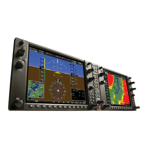
BENDIXKing XVUE TOUCH User manual

© Honeywell International Inc. Do not copy without express permission of Honeywell.
Honeywell International, Inc.
9201-B San Mateo Blvd N.E.
Albuquerque, New Mexico 87113
U.S.A.
Telephone: 855-250-7027 (Toll Free U.S.A./Canada)
Telephone: 602-365-7027 (International Direct)
XVUE TOUCH PRIMARY FLIGHT DISPLAY SYSTEM
INSTALLATION MANUAL
FOR USE IN NON-CERTIFIED AIRCRAFT
Document P/N 89000109-002 Rev 2
November 2019
Export Control
This document contains technical data and is subject to U.S. export regulations. These commodities,
technology, or software were exported from the United States in accordance with the export
administration regulations. Diversion contrary to U.S. law is prohibited.
ECCN: 7E994

89000109-002 xVue Installation Manual
Rev 2 Page T-1
© Honeywell International Inc. Do not copy without express permission of Honeywell.
For Use in Non-Certified Aircraft
Legal Notice
Proprietary Information
Honeywell - Confidential
THIS COPYRIGHTED WORK AND ALL INFORMATION ARE THE PROPERTY OF HONEYWELL INTERNATIONAL
INC., CONTAIN TRADE SECRETS AND MAY NOT, IN WHOLE OR IN PART, BE USED, DUPLICATED, OR
DISCLOSED FOR ANY PURPOSE WITHOUT PRIOR WRITTEN PERMISSION OF HONEYWELL INTERNATIONAL
INC. ALL RIGHTS RESERVED.
Honeywell Materials License Agreement
The documents and information contained herein (“the Materials”) are the proprietary data of
Honeywell International Inc. These Materials are provided for the exclusive use of Honeywell Service
Centers; Honeywell-authorized repair facilities; operators of Honeywell aerospace products subject to an
applicable product support agreement, their wholly owned-subsidiaries or a formally designated third
party service provider; and direct recipients of Materials from Honeywell’s Aerospace Technical
Publication Distribution.
The terms and conditions of this License Agreement govern your use of these Materials, except to the
extent that any terms and conditions of another applicable agreement with Honeywell regarding the
operation, maintenance, or repair of Honeywell aerospace products conflict with the terms and
conditions of this License Agreement, in which case the terms and conditions of the other agreement will
govern.
However, this License Agreement will govern in the event of a conflict between its terms and conditions
and those of a purchase order or acknowledgment.
(1) License Grant - If you are a party to an applicable product support agreement, a Honeywell Service
Center agreement, or an authorized repair facility agreement, Honeywell hereby grants you a limited,
non-exclusive license to use these Materials to operate, maintain, or repair Honeywell aerospace
products only in accordance with that agreement.
If you are a direct recipient of these Materials from Honeywell’s Aerospace Technical Publication
Distribution and are not a party to an agreement related to the operation, maintenance or repair of
Honeywell aerospace products, Honeywell hereby grants you a limited, non-exclusive license to use
these Materials to maintain or repair the subject Honeywell aerospace products only at the facility to
which these Materials have been shipped (“the Licensed Facility”). Transfer of the Materials to another
facility owned by you is permitted only if the original Licensed Facility retains no copies of the Materials
and you provide prior written notice to Honeywell.
(2) Rights In Materials - Honeywell retains all rights in these Materials and in any copies thereof that are
not expressly granted to you, including all rights in patents, copyrights, trademarks, and trade secrets. No
license to use any Honeywell trademarks or patents is granted under this License Agreement.
(3) Confidentiality - You acknowledge that these Materials contain information that is confidential and
proprietary to Honeywell. You agree to take all reasonable efforts to maintain the confidentiality of these
Materials.

89000109-002 xVue Installation Manual
Rev 2 Page T-2
© Honeywell International Inc. Do not copy without express permission of Honeywell.
For Use in Non-Certified Aircraft
(4) Assignment And Transfer - This License Agreement may be assigned to a formally designated service
designee or transferred to a subsequent owner or operator of an airplane containing the subject
Honeywell aerospace products. However, the recipient of any such assignment or transfer must assume
all of your obligations under this License Agreement. No assignment or transfer shall relieve any party of
any obligation that such party then has hereunder.
(5) Copies of Materials - Unless you have the express written permission of Honeywell, you may not make
or permit making of copies of the Materials. Notwithstanding the foregoing, you may make copies of only
portions of the Material for your internal use. You agree to return the Materials and any copies thereof to
Honeywell upon the request of Honeywell.
(6) Term - This License Agreement is effective until terminated as set forth herein. This License
Agreement will terminate immediately, without notice from Honeywell, if you fail to comply with any
provision of this License Agreement or will terminate simultaneously with the termination or expiration
of your applicable product support agreement, authorized repair facility agreement, or your formal
designation as a third party service provider. Upon termination of this License Agreement, you will return
these Materials to Honeywell without retaining any copies and will have one of your authorized officers
certify that all Materials have been returned with no copies retained.
(7) Remedies - Honeywell reserves the right to pursue all available remedies and damages resulting from
a breach of this License Agreement.
(8) Limitation of Liability - Honeywell does not make any representation regarding the use or sufficiency
of the Materials. THERE ARE NO OTHER WARRANTIES, WHETHER WRITTEN OR ORAL, EXPRESS, IMPLIED
OR STATUTORY, INCLUDING, BUT NOT LIMITED TO, (i) WARRANTIES ARISING FROM COURSE OF
PERFORMANCE, DEALING, USAGE, OR TRADE, WHICH ARE HEREBY EXPRESSLY DISCLAIMED, OR (ii)
WARRANTIES AGAINST INFRINGEMENT OF INTELLECTUAL PROPERTY RIGHTS OF THIRD PARTIES, EVEN IF
HONEYWELL HAS BEEN ADVISED OF ANY SUCH INFRINGEMENT. IN NO EVENT WILL HONEYWELL BE
LIABLE FOR ANY INCIDENTAL DAMAGES, CONSEQUENTIAL DAMAGES, SPECIAL DAMAGES, INDIRECT
DAMAGES, LOSS OF PROFITS, LOSS OF REVENUES, OR LOSS OF USE, EVEN IF INFORMED OF THE
POSSIBILITY OF SUCH DAMAGES. TO THE EXTENT PERMITTED BY APPLICABLE LAW, THESE LIMITATIONS
AND EXCLUSIONS WILL APPLY REGARDLESS OF WHETHER LIABILITY ARISES FROM BREACH OF CONTRACT,
WARRANTY, TORT (INCLUDING BUT NOT LIMITED TO NEGLIGENCE), BY OPERATION OF LAW, OR
OTHERWISE.
(9) Controlling Law - This License shall be governed and construed in accordance with the laws of the
State of New York without regard to the conflicts of laws provisions thereof. This license sets forth the
entire agreement between you and Honeywell and may only be modified by a writing duly executed by
the duly authorized representatives of the parties.

89000109-002 xVue Installation Manual
Rev 2 Page T-3
© Honeywell International Inc. Do not copy without express permission of Honeywell.
For Use in Non-Certified Aircraft
Safety Advisory
WARNING: BEFORE THE MATERIALS CALLED OUT IN THIS PUBLICATION ARE USED, KNOW THE
HANDLING,
STORAGE AND DISPOSAL PRECAUTIONS RECOMMENDED BY THE MANUFACTURER OR
SUPPLIER. FAILURE
TO OBEY THE MANUFACTURERS’ OR SUPPLIERS’ RECOMMENDATIONS CAN
RESULT IN PERSONAL INJURY
OR DISEASE.
This publication describes physical and chemical processes which can make it necessary to use chemicals,
solvents, paints, and other commercially available materials. The user of this publication must get the
Material
Safety Data Sheets (OSHA Form 174 or equivalent) from the manufacturers or suppliers of the
materials to be
used. The user must know the manufacturer/ supplier data and obey the procedures,
recommendations,
warnings and cautions set forth for the safe use, handling, storage, and disposal of the
materials.
Warranty/Liability Advisory
WARNING: HONEYWELL ASSUMES NO RESPONSIBILITY FOR ANY HONEYWELL EQUIPMENT WHICH
IS NOT
MAINTAINED AND/OR REPAIRED IN ACCORDANCE WITH HONEYWELL’S PUBLISHED
INSTRUCTIONS AND/
OR HONEYWELL’S FAA/SFAR 36 REPAIR AUTHORIZATION. NEITHER DOES
HONEYWELL ASSUME
RESPONSIBILITY FOR SPECIAL TOOLS AND TEST EQUIPMENT FABRICATED BY
COMPANIES OTHER THAN
HONEYWELL.
WARNING: INCORRECTLY REPAIRED COMPONENTS CAN AFFECT AIRWORTHINESS OR DECREASE
THE LIFE
OF THE COMPONENTS. INCORRECTLY FABRICATED SPECIAL TOOLING OR TEST
EQUIPMENT CAN RESULT IN
DAMAGE TO THE PRODUCT COMPONENTS OR GIVE UNSATISFACTORY
RESULTS.

89000109-002 xVue Installation Manual
Rev 2 Page T-4
© Honeywell International Inc. Do not copy without express permission of Honeywell.
For Use in Non-Certified Aircraft
Copyright - Notice
Copyright 2018, 2019 Honeywell International Inc. All rights reserved.
Honeywell is a registered trademark of Honeywell International Inc.
All other marks are owned by their respective companies.
Our products are under continuous research and development. Any information may therefore be
changed
without prior notice. Honeywell reserves the right to make improvements or changes in the
product described
in this manual at any time without notice. While reasonable efforts have been made in
the preparation of this
document to assure its accuracy, Honeywell assumes no liability resulting from
any errors or omissions in this
document, or from the use of the information contained herein.
Honeywell Aerospace Online Technical Publications Website
Go to the Honeywell Online Technical Publications Website at https://myaerospace.honeywell.com/.
To download or view publications online
1. To tell BendixKing of a possible data error in a publication.
2. Changes to this manual are provided to users who have registered via the xVue Touch website to
receive updates.
BendixKing Customer Support
If you need to speak to personnel about Technical matters, the BendixKing Customer Support team
provides 24/7 customer service.
• Telephone: 855-250-7027 (Toll Free U.S.A./Canada)
• Telephone: 602-365-7027 (International)
• Website: www.bendixking.com
• Email: techsupport@bendixking.com

89000109-002 xVue Installation Manual
Rev 2 Page T-5
© Honeywell International Inc. Do not copy without express permission of Honeywell.
For Use in Non-Certified Aircraft
RECORD OF REVISIONS
NOTE: The revision level for every page of this document will be updated during the revision process. A
list of effective pages is, therefore, not required.
Revision Revision Date Description
0 11Apr2018 Initial release
1 29June2018 Rewritten to update design details throughout
2 06Nov2019 Rewritten to update design details throughout

89000109-002 xVue Touch Installation Manual
Rev 2 Page T-1
© Honeywell International Inc. Do not copy without express permission of Honeywell.
For Use in Non-Certified Aircraft
TABLE OF CONTENTS
1 INTRODUCTION .......................................................................................... 1-1
1.1 How to Use This Manual .................................................................................................................... 1-1
1.1.1 General............................................................................................................................................ 1-1
1.1.2 Observance of Manual Instructions ................................................................................................ 1-1
1.1.3 Symbols ........................................................................................................................................... 1-1
1.1.4 Units of Measure............................................................................................................................. 1-1
1.1.5 Electrostatic Discharge .................................................................................................................... 1-1
1.2 References.......................................................................................................................................... 1-2
1.2.1 BendixKing/Vendor Publications ..................................................................................................... 1-2
1.2.2 Other Publications........................................................................................................................... 1-2
1.3 Acronyms and Abbreviations ............................................................................................................. 1-3
1.4 Terminology ....................................................................................................................................... 1-8
2 GENERAL INFORMATION ............................................................................ 2-1
2.1 Introduction........................................................................................................................................ 2-1
2.2 Scope .................................................................................................................................................. 2-1
2.3 xVue Touch Overview......................................................................................................................... 2-2
2.3.1 KSD 100EXP Primary Flight Display.................................................................................................. 2-3
2.3.2 KCP 100EXP Control Panel............................................................................................................... 2-3
2.3.3 KG 71EXP Air Data Attitude Heading Reference System (ADAHRS) ................................................ 2-4
2.3.4 KMG 7010/MD32 Magnetometer ................................................................................................... 2-4
2.3.5 KDC 100EXP Data Converter............................................................................................................ 2-4
2.3.6 KTP 73 OAT Probe ........................................................................................................................... 2-5
2.4 Technical Specifications ..................................................................................................................... 2-5
2.5 Environmental Qualification Form (EQF) ........................................................................................... 2-9
2.6 Regulatory Compliance .................................................................................................................... 2-19
2.7 Databases ......................................................................................................................................... 2-20
2.7.1 Navigation Database ..................................................................................................................... 2-20
2.7.2 Cartographic Database .................................................................................................................. 2-20
2.7.3 Obstacle Database......................................................................................................................... 2-20
2.7.4 Terrain Database ........................................................................................................................... 2-20
2.7.5 Instrument Procedure Charts Database........................................................................................ 2-20
2.7.6 Low Altitude Database .................................................................................................................. 2-20
2.7.7 High Altitude Database.................................................................................................................. 2-20
2.7.8 VFR Sectional Database................................................................................................................. 2-20
2.8 Synthetic Vision ................................................................................................................................ 2-20
2.9 Recommended Standby Instruments............................................................................................... 2-21
2.10 Required GPS Navigator ................................................................................................................. 2-21
2.11 Installation Limitations................................................................................................................... 2-21
2.12 Permission ...................................................................................................................................... 2-23
2.13 Repair and Return .......................................................................................................................... 2-23
3 XVUE TOUCH SYSTEM INSTALLATION OVERVIEW ....................................... 3-1
3.1 Pre-Installation Checklist.................................................................................................................... 3-3
3.2 Available Equipment .......................................................................................................................... 3-5
3.3 Installation Materials.......................................................................................................................... 3-5
3.3.1 Accessories and Support Equipment Available from BendixKing.................................................... 3-9
3.3.2 Materials Required but Not Supplied.............................................................................................. 3-9

89000109-002 xVue Touch Installation Manual
Rev 2 Page T-2
© Honeywell International Inc. Do not copy without express permission of Honeywell.
For Use in Non-Certified Aircraft
3.3.3 Tools Required but Not Supplied .................................................................................................. 3-11
3.4 Unpacking and Inspection ................................................................................................................ 3-12
3.5 System Interfaces ............................................................................................................................. 3-13
3.5.1 Standard Interface Definitions ...................................................................................................... 3-13
3.5.1.1 Discrete I/O ................................................................................................................................ 3-13
3.5.1.1.1 Discrete Inputs ........................................................................................................................ 3-13
3.5.1.1.2 Discrete Outputs ..................................................................................................................... 3-14
3.5.1.2 Serial I/O..................................................................................................................................... 3-14
3.5.1.3 ARINC 429 I/O............................................................................................................................. 3-14
3.5.1.4 ARINC 453 I/O............................................................................................................................. 3-14
3.6 Installation Considerations............................................................................................................... 3-14
3.6.1 xVue Touch System Interfaces ...................................................................................................... 3-15
3.6.2 Instrument Panel........................................................................................................................... 3-18
3.6.3 Standby Instruments ..................................................................................................................... 3-19
3.6.3.1 Standby Instrument Location ..................................................................................................... 3-19
3.6.3.2 Standby Attitude Indicator ......................................................................................................... 3-19
3.6.3.3 Standby Airspeed Indicator ........................................................................................................ 3-20
3.6.3.4 Standby Altimeter ...................................................................................................................... 3-20
3.6.4 Required GPS Navigator ................................................................................................................ 3-20
3.6.5 KSD 100EXP Installation Considerations ....................................................................................... 3-20
3.6.5.1 KSD 100EXP – Field of View Considerations............................................................................... 3-20
3.6.5.2 KSD 100EXP Cooling Considerations .......................................................................................... 3-22
3.6.6 KCP 100EXP Installation Considerations........................................................................................ 3-22
3.6.6.1 KCP 100EXP Location.................................................................................................................. 3-22
3.6.7 KG 71EXP Installation Considerations ........................................................................................... 3-23
3.6.7.1 KG 71EXP Location ..................................................................................................................... 3-23
3.6.7.2 KG 71EXP Orientation................................................................................................................. 3-24
3.6.7.3 KG 71EXP Cooling Considerations .............................................................................................. 3-25
3.6.8 KMG 7010/MD32 Installation Considerations...............................................................................3-25
3.6.8.1 KMG 7010/MD32 Location......................................................................................................... 3-25
3.6.8.2 KMG 7010/MD32 Orientation.................................................................................................... 3-25
3.6.8.3 Magnetic Interference................................................................................................................ 3-26
3.6.8.3.1 Ground Checks - Prior to Installation of the Magnetometer .................................................. 3-26
3.6.8.3.2 Ground Checks - After Magnetometer Installation and Compass Swing ................................ 3-26
3.6.9 KDC 100EXP Installation Considerations ....................................................................................... 3-27
3.6.9.1 KDC 100EXP Location ................................................................................................................. 3-27
3.6.9.2 KDC 100EXP Orientation............................................................................................................. 3-27
3.6.10 KTP 73 Installation Considerations.............................................................................................. 3-27
3.6.10.1 KTP 73 Location ........................................................................................................................ 3-27
3.7 Placards and Labels .......................................................................................................................... 3-29
3.8 Power Distribution ........................................................................................................................... 3-29
3.8.1 Circuit Protection .......................................................................................................................... 3-29
3.9 Cable and Wiring .............................................................................................................................. 3-29
3.9.1 Shield Termination ........................................................................................................................ 3-30
3.10 Electrical Bonding Considerations .................................................................................................. 3-30
3.11 Pitot-Static Plumbing Considerations............................................................................................. 3-31
3.12 External Annunciators .................................................................................................................... 3-31
3.13 External System Interface Considerations ..................................................................................... 3-31
3.13.1 Navigation Receiver..................................................................................................................... 3-31
3.13.2 ADS-B Traffic, FIS-B Weather and TFRs ....................................................................................... 3-31

89000109-002 xVue Touch Installation Manual
Rev 2 Page T-3
© Honeywell International Inc. Do not copy without express permission of Honeywell.
For Use in Non-Certified Aircraft
3.13.3 Autopilot Interface ...................................................................................................................... 3-31
3.13.3.1 Autopilot Attitude Indicators/Gyros ........................................................................................ 3-32
3.13.3.2 Autopilot Turn Coordinators .................................................................................................... 3-32
3.13.3.3 Autopilot Altitude Pre-Selector and Remote Annunciators ..................................................... 3-32
3.13.4 Audio Panel ................................................................................................................................. 3-32
3.14 Part 121/Part 135 Considerations .................................................................................................. 3-32
4 XVUE TOUCH SYSTEM INSTALLATION PROCEDURES.................................... 4-1
4.1 Introduction........................................................................................................................................ 4-1
4.2 Instrument Panel Preparation Procedure .......................................................................................... 4-1
4.3 KSD 100EXP Installation ..................................................................................................................... 4-2
4.3.1 KSD 100EXP Connectors/Configuration Module ............................................................................. 4-2
4.3.1.1 J1 Connector Assembly ................................................................................................................ 4-3
4.3.1.2 J2 Connector/Configuration Module Assembly ........................................................................... 4-4
4.3.2 KSD 100EXP Installation Procedures ............................................................................................... 4-7
4.3.3 KSD 100EXP Installation Unit Verification ....................................................................................... 4-9
4.4 KCP 100EXP Installation.................................................................................................................... 4-10
4.4.1 KCP 100EXP Instrument Panel Installation Procedures................................................................. 4-10
4.4.2 KCP 100EXP Center Stack Installation Procedures ........................................................................ 4-11
4.4.3 KCP 100EXP Post Installation Unit Verification ............................................................................. 4-11
4.5 KG 71EXP Installation ....................................................................................................................... 4-12
4.5.1 KG 71EXP Installation Procedures ................................................................................................. 4-12
4.5.2 KG 71EXP Post Installation Unit Verification ................................................................................. 4-13
4.6 KMG 7010 Installation...................................................................................................................... 4-14
4.6.1 KMG 7010 Installation Procedures................................................................................................ 4-14
4.6.2 KMG 7010 – Post Installation Unit Verification............................................................................. 4-16
4.7 MD32 Installation............................................................................................................................. 4-16
4.7.1 MD32 – Post Installation Unit Verification.................................................................................... 4-16
4.8 KDC 100EXP Installation ................................................................................................................... 4-16
4.8.1 KDC 100EXP Installation Procedures ............................................................................................. 4-17
4.8.2 KDC 100EXP – Post Installation Unit Verification .......................................................................... 4-19
4.9 KTP 73 Installation............................................................................................................................ 4-19
4.9.1 KTP 73 Installation Procedures...................................................................................................... 4-19
4.9.2 KTP 73 - Post Installation Unit Verification ................................................................................... 4-20
4.10 xVue Touch System Components and Wiring Location Data ......................................................... 4-20
4.10.1 Wiring Harness ............................................................................................................................ 4-20
4.11 Weight and Balance Analysis.......................................................................................................... 4-21
4.12 Aircraft Electrical Load Analysis (ELA) ............................................................................................ 4-23
4.12.1 Aircraft with Existing ELA ............................................................................................................ 4-23
4.12.2 Aircraft without an Existing ELA - Measurement Method .......................................................... 4-23
4.12.3 Aircraft without an Existing ELA - Analysis Method .................................................................... 4-24
4.13 Airplane Flight Procedures (AFP).................................................................................................... 4-24
5 CONNECTOR PINOUT INFORMATION.......................................................... 5-1
5.1 KSD 100EXP ........................................................................................................................................ 5-1
5.2 KCP 100EXP ........................................................................................................................................ 5-6
5.3 KG 71EXP ............................................................................................................................................ 5-6
5.3.1 KG 71EXP Connector – J71 .............................................................................................................. 5-6
5.3.2 KG 71EXP Pressure Ports ................................................................................................................. 5-8
5.3.3 KG 71EXP Maintenance Port ........................................................................................................... 5-9
5.4 KMG 7010........................................................................................................................................... 5-9

89000109-002 xVue Touch Installation Manual
Rev 2 Page T-4
© Honeywell International Inc. Do not copy without express permission of Honeywell.
For Use in Non-Certified Aircraft
5.5 MD32................................................................................................................................................ 5-10
5.6 KDC 100EXP ...................................................................................................................................... 5-11
5.7 KTP 73............................................................................................................................................... 5-12
5.8 Configuration Module ...................................................................................................................... 5-12
6 SYSTEM CONFIGURATION........................................................................... 6-1
6.1 Mounting, Wiring, and Power Checks ................................................................................................ 6-3
6.2 KSD 100EXP Configuration (PFD) Setup.............................................................................................. 6-4
6.2.1 System Configuration Setup............................................................................................................ 6-8
6.2.1.1 Lighting ......................................................................................................................................... 6-9
6.2.1.2 External Dimming ......................................................................................................................... 6-9
6.2.1.3 Aircraft Tail Number................................................................................................................... 6-12
6.2.1.4 Aircraft Serial Number................................................................................................................ 6-13
6.2.1.5 Aircraft Pitch Bias ....................................................................................................................... 6-13
6.2.1.6 Pilot V-Speed Locking ................................................................................................................. 6-14
6.2.1.7 Engine Configuration.................................................................................................................. 6-15
6.2.1.8 Units Configuration .................................................................................................................... 6-15
6.2.2 PFD Configuration Setup ............................................................................................................... 6-16
6.2.2.1 Vertical Speed Indicator Range .................................................................................................. 6-17
6.2.2.2 Airspeed ..................................................................................................................................... 6-18
6.2.2.3 Master Audio Volume ................................................................................................................ 6-21
6.2.2.4 Terrain Awareness and Warning System (TAWS) Toggle ........................................................... 6-22
6.2.2.5 KSD Altitude Preselect Toggle .................................................................................................... 6-23
6.2.3 GPS/NAV Configuration Setup ...................................................................................................... 6-23
6.2.3.1 GPS Navigation Source ............................................................................................................... 6-25
6.2.3.2 VLOC Navigation Source............................................................................................................. 6-26
6.2.4 Autopilot Configuration Setup ...................................................................................................... 6-29
6.2.4.1 AP Computer .............................................................................................................................. 6-31
6.2.4.2 Sync FD Offset ............................................................................................................................ 6-32
6.2.4.3 Sync FD Gain............................................................................................................................... 6-32
6.2.4.4 GPSS K Factor ............................................................................................................................. 6-32
6.2.5 Broadcast WX Configuration ......................................................................................................... 6-34
6.2.6 Traffic Configuration Setup ........................................................................................................... 6-35
6.2.7 Save & Exit Configuration Mode ................................................................................................... 6-37
6.3 KG 71EXP Configuration (ADAHRS) .................................................................................................. 6-37
6.3.1 KG 71EXP Maintenance Interface Configuration........................................................................... 6-38
6.3.1.1 KG 71EXP Orientation................................................................................................................. 6-39
6.3.1.2 KG 71EXP Digital I/O Configuration ............................................................................................ 6-41
6.3.1.3 ARINC 429 Transmit Channel Configuration ..............................................................................6-42
6.3.1.3.1 Same as Tx0 (for KSD 100EXP)................................................................................................. 6-43
6.3.1.3.2 Attitude & Heading.................................................................................................................. 6-43
6.3.1.3.3 Altitude & Temperature .......................................................................................................... 6-43
6.3.1.3.4 Air Data.................................................................................................................................... 6-44
6.3.1.3.5 Attitude Interface.................................................................................................................... 6-44
6.3.1.3.6 Altitude Interface .................................................................................................................... 6-44
6.3.1.3.7 Custom Configuration ............................................................................................................. 6-44
6.3.1.4 KG 71EXP Transponder Serial Interface ..................................................................................... 6-47
6.4 KMG 7010/MD32 Calibration (Magnetometer) ............................................................................... 6-47
6.4.1 Magnetometer Installation Orientation........................................................................................ 6-49
6.4.2 Magnetometer Compensation...................................................................................................... 6-51
6.5 KTP 73 Configuration (Outside Air Temperature Probe).................................................................. 6-53

89000109-002 xVue Touch Installation Manual
Rev 2 Page T-5
© Honeywell International Inc. Do not copy without express permission of Honeywell.
For Use in Non-Certified Aircraft
7 SYSTEM CHECKOUT .................................................................................... 7-1
7.1 Recommended Test Equipment ......................................................................................................... 7-1
7.2 xVue Touch System Post Installation System Checkout..................................................................... 7-1
7.2.1 Attitude Checkout ........................................................................................................................... 7-2
7.2.2 Heading Checkout ........................................................................................................................... 7-2
7.2.3 Leak Test.......................................................................................................................................... 7-2
7.2.4 Altitude Display/Vertical Display and Standby Altimeter Checkout................................................ 7-2
7.2.5 Airspeed Display and Standby Airspeed Indicator Checkout .......................................................... 7-4
7.2.6 Outside Air Temperature Checkout ................................................................................................ 7-5
7.2.7 GPS Receiver.................................................................................................................................... 7-5
7.2.8 NAV Receiver................................................................................................................................... 7-8
7.2.9 Universal Access Transceiver (UAT) Checkout .............................................................................. 7-11
7.2.10 Autopilot System Setup............................................................................................................... 7-12
7.2.10.1 Autopilot & KSD 100EXP Interface ........................................................................................... 7-12
7.2.10.2 Autopilot & KSD 100EXP Interface Checkout Procedures ........................................................ 7-12
7.2.11 KCP 100EXP Checkout ................................................................................................................. 7-13
7.2.12 Interfaced Subsystem Checkout.................................................................................................. 7-13
7.2.12.1 Navigator.................................................................................................................................. 7-13
7.2.12.2 TAWS/Traffic ............................................................................................................................ 7-13
7.2.13 Lighting Checkout........................................................................................................................ 7-13
7.3 EMI Interaction Checkout................................................................................................................. 7-14
7.4 Post Installation Flight Checks.......................................................................................................... 7-14
7.5 Post Installation Activities ................................................................................................................ 7-14
7.5.1 Database Updates ......................................................................................................................... 7-14
7.5.1.1 USB Database Loading................................................................................................................ 7-15
7.5.1.2 Wi-Fi Database Loading.............................................................................................................. 7-19
7.5.1.2.1 Wingman Services Databases.................................................................................................. 7-19
7.5.1.2.2 Seattle Avionics Databases...................................................................................................... 7-22
7.5.1.3 Database Loading Errors ............................................................................................................ 7-27
7.5.1.3.1 USB Database Loading Errors .................................................................................................. 7-27
7.5.1.3.2 Wi-Fi Database Loading Errors ................................................................................................ 7-28
7.5.2 xVue Touch Flight Software Update.............................................................................................. 7-30
7.5.2.1 KSD 100EXP Software Update .................................................................................................... 7-30
7.5.2.1.1 KSD 100EXP Software Field Loading Procedure ...................................................................... 7-31
7.5.2.2 KSD 100EXP Software Loading Errors......................................................................................... 7-34
7.5.2.3 KG 71EXP Software Update........................................................................................................ 7-34
8 TROUBLESHOOTING ................................................................................... 8-1
8.1 Built-in-Test (BIT) Function................................................................................................................. 8-4
8.1.1 P-BIT ................................................................................................................................................ 8-4
8.1.2 C-BIT ................................................................................................................................................ 8-5
8.2 KSD 100EXP Touch Calibration ........................................................................................................... 8-7
8.2.1 KSD 100EXP Manual Touch Calibration ........................................................................................... 8-7
8.2.2 Default Touch Calibration.............................................................................................................. 8-10
8.3 KG 71EXP Troubleshooting............................................................................................................... 8-12
8.4 KMG 7010/MD32 Troubleshooting .................................................................................................. 8-17
8.4.1 Troubleshooting – Continuous Measurement Disturbances ........................................................ 8-17
8.4.2 Troubleshooting – Significant Difference between Required and Sensed Heading...................... 8-17
8.5 Alerts ................................................................................................................................................ 8-17
8.6 Repair and Return ............................................................................................................................ 8-23

89000109-002 xVue Touch Installation Manual
Rev 2 Page T-6
© Honeywell International Inc. Do not copy without express permission of Honeywell.
For Use in Non-Certified Aircraft
9 INSTRUCTIONS FOR CONTINUED AIRWORTHINESS ..................................... 9-1
9.1 Purpose .............................................................................................................................................. 9-1
9.2 ICA Content ........................................................................................................................................ 9-1
9.2.1 Description of System and Installation............................................................................................ 9-1
9.2.2 Airworthiness Limitations and Scheduled Maintenance................................................................. 9-1
9.2.2.1 Airworthiness Limitations ............................................................................................................ 9-1
9.2.2.2 Scheduled Maintenance Checks................................................................................................... 9-1
9.2.3 Control and Operating Information ................................................................................................ 9-1
9.2.4 Unscheduled Maintenance ............................................................................................................. 9-1
9.2.4.1 Cleaning........................................................................................................................................ 9-1
9.2.4.2 Screen Cleaning ............................................................................................................................ 9-2
9.2.4.3 IR Bar Cleaning ............................................................................................................................. 9-2
9.2.4.4 Inspection..................................................................................................................................... 9-3
9.2.4.5 Configuration Module Inspection ................................................................................................ 9-3
9.2.4.6 xVue Touch System Bonding Inspection ...................................................................................... 9-3
9.2.4.7 Inspection Criteria ........................................................................................................................ 9-4
9.2.4.8 Adjustments ................................................................................................................................. 9-8
9.2.4.9 Testing .......................................................................................................................................... 9-8
9.2.4.10 Lubrication.................................................................................................................................. 9-8
9.2.5 Servicing Information ...................................................................................................................... 9-8
9.2.6 Troubleshooting .............................................................................................................................. 9-8
9.2.7 Storage Limitation ........................................................................................................................... 9-8
9.2.8 Removal and Reinstallation Information......................................................................................... 9-8
9.2.8.1 Removal........................................................................................................................................ 9-8
9.2.8.1.1 KSD 100EXP Removal ................................................................................................................ 9-8
9.2.8.1.2 KCP 100EXP Removal................................................................................................................. 9-9
9.2.8.1.3 KTP 73 Removal......................................................................................................................... 9-9
9.2.8.1.4 KG 71EXP Removal .................................................................................................................... 9-9
9.2.8.1.5 KMG 7010 Removal................................................................................................................... 9-9
9.2.8.1.6 MD32 Removal.......................................................................................................................... 9-9
9.2.8.1.7 KDC 100EXP Removal ................................................................................................................ 9-9
9.2.8.2 Reinstallation.............................................................................................................................. 9-10
9.2.8.2.1 KSD 100EXP Reinstallation ...................................................................................................... 9-10
9.2.8.2.2 KCP 100EXP Reinstallation ...................................................................................................... 9-10
9.2.8.2.3 KTP 73 Reinstallation............................................................................................................... 9-10
9.2.8.2.4 KG 71EXP Reinstallation .......................................................................................................... 9-10
9.2.8.2.5 KMG 7010 Reinstallation......................................................................................................... 9-10
9.2.8.2.6 MD32 Reinstallation................................................................................................................ 9-10
9.2.8.2.7 KDC 100 EXP Reinstallation ..................................................................................................... 9-10
9.2.8.3 Return to Service........................................................................................................................ 9-11
APPENDIX A OUTLINE AND INSTALLATION DRAWINGS....................................A-1
APPENDIX B INTERCONNECT DIAGRAMS.........................................................B-1
APPENDIX C XVUE TOUCH SYSTEM INSTALLATION WORKSHEET...................... C-1
APPENDIX D MD32 INSTALLATION MANUAL ...................................................D-1

89000109-002 xVue Touch Installation Manual
Rev 2 Page T-1
© Honeywell International Inc. Do not copy without express permission of Honeywell.
For Use in Non-Certified Aircraft
LIST OF FIGURES
Figure 1-1 Symbols ..................................................................................................................... 1-1
Figure 2-1 xVue Touch System Components.............................................................................. 2-2
Figure 2-2 xVue Touch System Block Diagram ........................................................................... 2-3
Figure 2-3 Standby Instrument Power Requirements.............................................................. 2-22
Figure 3-1 Example Instrument Panel Modification................................................................... 3-1
Figure 3-2 xVue Touch System Interfaces ................................................................................ 3-15
Figure 3-3 KSD 100EXP Primary Field of View .......................................................................... 3-21
Figure 3-4 KSD 100EXP Location (Attitude Indicator)............................................................... 3-22
Figure 3-5 Supported KG 71EXP Installation Orientations ....................................................... 3-24
Figure 3-6 Lightning Zones ....................................................................................................... 3-28
Figure 3-7 Termination Procedure ........................................................................................... 3-30
Figure 4-1 KSD 100EXP (Back View)............................................................................................ 4-2
Figure 4-2 BendixKing Backshell Assembly................................................................................. 4-3
Figure 4-3 KSD 100EXP J1 Connector Assembly ......................................................................... 4-3
Figure 4-4 KSD 100EXP J2 Connector Assembly ......................................................................... 4-4
Figure 4-5 Configuration Module Circuit Card Assembly (Primary Side)................................... 4-4
Figure 4-6 Configuration Module Inside J2 Backshell................................................................. 4-5
Figure 4-7 Wired Configuration Module Circuit Card Assembly ............................................... 4-6
Figure 4-8 Bottom Side of J2 Backshell ...................................................................................... 4-6
Figure 4-9 KSD 100EXP Grip Installation (Sheet 1 of 2) .............................................................. 4-7
Figure 4-10 KSD 100EXP Grip Installation (Sheet 2 of 2) ............................................................ 4-8
Figure 4-11 KSD 100EXP Installation .......................................................................................... 4-9
Figure 4-12 KCP 100EXP Installation ........................................................................................ 4-10
Figure 4-13 KCP 100EXP Landscape Center Stack Installation ................................................. 4-11
Figure 4-14 KG 71EXP ADAHRS Installation Diagram ............................................................... 4-12
Figure 4-15 KG 71EXP Pressure Fitting Identification Diagram ................................................ 4-13
Figure 4-16 KMG 7010 Magnetometer .................................................................................... 4-14
Figure 4-17 KMG 7010 Magnetometer Installation Diagram ................................................... 4-15
Figure 4-18 KDC 100EXP Connector ......................................................................................... 4-16
Figure 4-19 KDC 100EXP Data Connector Installation Diagram ............................................... 4-18
Figure 4-20 KTP 73 Installation Diagram .................................................................................. 4-20
Figure 5-1 Pressure Port Fitting(s).............................................................................................. 5-8
Figure 5-2 KMG 7010 Backshell................................................................................................ 5-10
Figure 5-3 KDC 100EXP Backshell ............................................................................................. 5-11
Figure 6-1 KSD 100EXP Installation/Maintenance Functional Diagram ..................................... 6-2
Figure 6-2 KG 71EXP Installation/Maintenance Functional Diagram ......................................... 6-3
Figure 6-3 Database Acknowledge Screen ................................................................................. 6-4
Figure 6-4 APM Configuration Mismatch Screen ....................................................................... 6-5
Figure 6-5 Config Mode Screen .................................................................................................. 6-5
Figure 6-6 Configuration Preview Window ................................................................................ 6-6
Figure 6-7 Installer Main Menu.................................................................................................. 6-7
Figure 6-8 System Config Sub-Menu .......................................................................................... 6-8
Figure 6-9 Lighting Sub-Menu .................................................................................................... 6-9

89000109-002 xVue Touch Installation Manual
Rev 2 Page T-2
© Honeywell International Inc. Do not copy without express permission of Honeywell.
For Use in Non-Certified Aircraft
Figure 6-10 External Dimming Calibration Sub-Menu................................................................ 6-9
Figure 6-11 Minimum Brightness Level.................................................................................... 6-10
Figure 6-12 Maximum Brightness Levels.................................................................................. 6-11
Figure 6-13 A/C Tail # Keypad .................................................................................................. 6-12
Figure 6-14 A/C Tail Number.................................................................................................... 6-12
Figure 6-15 A/C Serial # Keypad ............................................................................................... 6-13
Figure 6-16 A/C Serial # ............................................................................................................ 6-13
Figure 6-17 Pitch Bias Keypad .................................................................................................. 6-14
Figure 6-18 Pitch Bias ............................................................................................................... 6-14
Figure 6-19 Pilot V-Spd Locked/Unlocked Toggle .................................................................... 6-15
Figure 6-20 Engine Configuration............................................................................................. 6-15
Figure 6-21 Units Configuration ............................................................................................... 6-15
Figure 6-22 Message Center Caution for V-Speed Unit Changes ............................................. 6-16
Figure 6-23 PFD Sub-Menu....................................................................................................... 6-16
Figure 6-24 Vertical Speed Tape Examples (1/2 PFD View)...................................................... 6-17
Figure 6-25 VSI Selection Menu ............................................................................................... 6-18
Figure 6-26 V-Speed Tape Illustration ...................................................................................... 6-19
Figure 6-27 Airspeed Sub-Menu............................................................................................... 6-20
Figure 6-28 VNE V-Speed Keypad Example .............................................................................. 6-21
Figure 6-29 Master VOL Sub-Menu .......................................................................................... 6-22
Figure 6-30 TAWS Toggle ......................................................................................................... 6-22
Figure 6-31 GPS/NAV Sub-Menu.............................................................................................. 6-23
Figure 6-32 GPS 1 Sub-Menu.................................................................................................... 6-25
Figure 6-33 GPS2 Sub-Menu..................................................................................................... 6-26
Figure 6-34 VLOC1 Sub-Menu .................................................................................................. 6-27
Figure 6-35 VLOC2 Sub-Menu .................................................................................................. 6-28
Figure 6-36 Autopilot Sub-Menu.............................................................................................. 6-29
Figure 6-37 AP Computer Sub-Menu ....................................................................................... 6-31
Figure 6-38 AP Computer ......................................................................................................... 6-32
Figure 6-39 GPSS K Factor Keypad............................................................................................ 6-33
Figure 6-40 GPSS K Factor ........................................................................................................ 6-33
Figure 6-41 Broadcast WX Sub-Menu ...................................................................................... 6-34
Figure 6-42 Broadcast LRU Sub-Menu...................................................................................... 6-35
Figure 6-43 Traffic Sub-Menu................................................................................................... 6-36
Figure 6-44 ADS-B Sub-Menu ................................................................................................... 6-36
Figure 6-45 Installer Menu Closed ........................................................................................... 6-37
Figure 6-46 CMT Startup Screen .............................................................................................. 6-38
Figure 6-47 CMT Main Configuration Screen ........................................................................... 6-39
Figure 6-48 KG 71EXP Orientation Drop-Down List.................................................................. 6-40
Figure 6-49 CMT Confirmation of Orientation and Offsets Store ............................................ 6-41
Figure 6-50 CMT Page for Digital I/O Configuration................................................................. 6-42
Figure 6-51 KG 71EXP ARINC Transmit Drop-down List ........................................................... 6-43
Figure 6-52 ARINC Transmit Channel Custom Configuration ................................................... 6-46
Figure 6-53 KMG 7010 Calibration Page .................................................................................. 6-49
Figure 6-54 X, Y, Z Axis Positive Direction ................................................................................ 6-50
Figure 6-55 KMG 7010/MD32 Calibration Reading .................................................................. 6-52

89000109-002 xVue Touch Installation Manual
Rev 2 Page T-3
© Honeywell International Inc. Do not copy without express permission of Honeywell.
For Use in Non-Certified Aircraft
Figure 6-56 Completion of Magnetometer Calibration............................................................ 6-53
Figure 7-1 KSD 100EXP Screen ................................................................................................... 7-1
Figure 7-2 Menu Button ............................................................................................................. 7-1
Figure 7-3 PFD Setup Sub-Menu ................................................................................................ 7-4
Figure 7-4 Airspeed Labels Button ............................................................................................. 7-4
Figure 7-5 CDI Source Sub-Menu (Options Shown For Reference) ............................................ 7-5
Figure 7-6 Main Menu................................................................................................................ 7-6
Figure 7-7 PFD Menu.................................................................................................................. 7-6
Figure 7-8 Bearing Pointers Sub-Menu ...................................................................................... 7-7
Figure 7-9 Pointer 1 Sub-Menu .................................................................................................. 7-7
Figure 7-10 CRS Button (Value Shown for Reference Only) ....................................................... 7-9
Figure 7-11 SYNC Button (Value Shown for Reference Only)..................................................... 7-9
Figure 7-12 UAT Fail Message .................................................................................................. 7-12
Figure 7-13 System Tools Menu ............................................................................................... 7-15
Figure 7-14 Database Loading Tool Button .............................................................................. 7-15
Figure 7-15 Database Loading Menu........................................................................................ 7-16
Figure 7-16 Database Loading Page (Unpacking) ..................................................................... 7-16
Figure 7-17 Database Loading Page ......................................................................................... 7-17
Figure 7-18 Database Install Buttons ....................................................................................... 7-17
Figure 7-19 Database Loading in Progress Screen.................................................................... 7-18
Figure 7-20 Database Loading Complete ................................................................................. 7-18
Figure 7-21 KSD 100 Wi-Fi Connection Enabled....................................................................... 7-19
Figure 7-22 Connected to KSD Wi-Fi ........................................................................................ 7-20
Figure 7-23 DataManager Lite Main Page................................................................................ 7-20
Figure 7-24 Wi-Fi Webpage with Selected Database ............................................................... 7-21
Figure 7-25 Uploading Databases to KSD 100EXP .................................................................... 7-21
Figure 7-26 Verifying Databases............................................................................................... 7-21
Figure 7-27 Wi-Fi Database Loading Complete ........................................................................ 7-22
Figure 7-28 Restart KSD 100EXP Window ................................................................................ 7-22
Figure 7-29 FlyQ App Main Screen ........................................................................................... 7-23
Figure 7-30 ChartData Manager Screen ................................................................................... 7-24
Figure 7-31 FlyQ Application Detected Window ...................................................................... 7-25
Figure 7-32 FlyQ Database Update Available Window............................................................ 7-26
Figure 7-33 Performing FlyQ Database Update Window ......................................................... 7-26
Figure 7-34 Performing FlyQ Database Update Progress Window .......................................... 7-26
Figure 7-35 Database(s) Update Complete Window................................................................ 7-27
Figure 7-36 Database Loading Completed with Errors Window .............................................. 7-28
Figure 7-37 Wi-Fi Serial Number Mismatch Example............................................................... 7-28
Figure 7-38 FlyQ Database Update Error Message .................................................................. 7-29
Figure 7-39 FlyQ Wi-Fi Connection Failed Message ................................................................. 7-30
Figure 7-40 Software Loading Sub-Menu (Check for USB Updates)......................................... 7-31
Figure 7-41 Software Loading Sub-Menu (New Software Found)............................................ 7-32
Figure 7-42 Software Loading Pop-Up Window (Initiate) ........................................................ 7-32
Figure 7-43 Software Loading Pop-Up Window (Loading In Progress) .................................... 7-32
Figure 7-44 Software Loading Pop-Up Window (Loading Complete)....................................... 7-33
Figure 7-45 Software Loading Pop-Up Window (Power Cycle) ................................................ 7-33

89000109-002 xVue Touch Installation Manual
Rev 2 Page T-4
© Honeywell International Inc. Do not copy without express permission of Honeywell.
For Use in Non-Certified Aircraft
Figure 7-46 Restore Data to APM............................................................................................. 7-33
Figure 8-1 Screen Maint Menu................................................................................................... 8-7
Figure 8-2 Manual Touch Calibration Menu............................................................................... 8-7
Figure 8-3 Example of Touch Calibration Utility Screen ............................................................. 8-8
Figure 8-4 Example of the Touch Calibration Utility Test Screen ............................................... 8-9
Figure 8-5 Reverting Touch Calibration Screen ........................................................................ 8-10
Figure 8-6 Restore Def. Touch Cal. Screen ............................................................................... 8-10
Figure 8-7 Restoration of Default Values Successful Screen .................................................... 8-11
Figure A-1 KSD 100EXP Center of Gravity................................................................................... A-1
Figure A-2 KSD 100EXP Panel Cutout Dimensions...................................................................... A-2
Figure A-3 KCP 100EXP Dimensions and Center of Gravity - Portrait Orientation ..................... A-3
Figure A-4 KCP 100EXP Dimensions and Center of Gravity - Landscape Orientation................. A-4
Figure A-5 KCP 100EXP Panel Cutout Dimensions...................................................................... A-5
Figure A-6 KG 71EXP Dimensions and Center of Gravity............................................................ A-6
Figure A-7 KG 71EXP Mounting Hole Pattern Diagram .............................................................. A-7
Figure A-8 KMG 7010 Outline and Mounting Drawing (Sheet 1 of 2) ........................................ A-8
Figure A-9 KMG 7010 Outline and Mounting Drawing (Sheet 2 of 2 ......................................... A-9
Figure A-10 MD32 Outline Drawing ......................................................................................... A-10
Figure A-11 KDC 100EXP Outline and Mounting Drawing (Sheet 1 of 2) ................................. A-11
Figure A-12 KDC 100EXP Outline and Mounting Drawing (Sheet 2 of 2) ................................. A-12
Figure A-13 KTP 73 Dimensions and Center of Gravity ............................................................ A-13
Figure A-14 KTP 73 Mounting Hole Pattern ............................................................................. A-14
Figure A-15 KTP 73 Generic Doubler (for 0.016 - 0.032 Inch Skin Thickness) .......................... A-14
Figure B-1 xVue Touch Power Connection Diagrams ................................................................. B-1
Figure B-2 Autopilot Interconnect Diagram ............................................................................... B-2
Figure B-3 Weather and Traffic Interconnect Diagram .............................................................. B-3
Figure B-4 Navigation Interconnect Diagram ............................................................................. B-4
Figure B-5 Audio Panel Interconnect Diagram ........................................................................... B-5
Figure B-6 KSD 100EXP LRU Interconnect Diagram.................................................................... B-6
Figure B-7 KG 71 LRU Interconnect Diagram - 1......................................................................... B-7
Figure B-8 KG 71 LRU Interconnect Diagram - 2......................................................................... B-8
Figure B-9 KG 71 LRU Interconnect Diagram - 3......................................................................... B-9
Figure B-10 KG 71 LRU Interconnect Diagram - 4..................................................................... B-10
Figure C-1 xVue Touch System Components and Cable Routing (Top View) ............................. C-2
Figure C-2 xVue Touch System Components and Cable Routing (Side View) ............................ C-3
Figure C-3 xVue Touch System Circuit Breakers and Switch Locations ...................................... C-3

89000109-002 xVue Touch Installation Manual
Rev 2 Page T-1
© Honeywell International Inc. Do not copy without express permission of Honeywell.
For Use in Non-Certified Aircraft
LIST OF TABLES
Table 1-1 BendixKing/Vendor References...................................................................................1-2
Table 1-2 Standard References ................................................................................................... 1-2
Table 1-3 Acronyms and Abbreviations....................................................................................... 1-3
Table 2-1 xVue Touch System Components ................................................................................2-1
Table 2-2 KSD 100EXP Primary Flight Display Specifications.......................................................2-5
Table 2-3 KCP 100EXP Control Panel Specifications.................................................................... 2-5
Table 2-4 KG 71EXP ADAHRS Specifications................................................................................ 2-6
Table 2-5 KG 71EXP ADAHRS Performance Characteristics.........................................................2-6
Table 2-6 KMG 7010 Magnetometer Specifications.................................................................... 2-7
Table 2-7 MD32 Magnetometer Specifications...........................................................................2-7
Table 2-8 KDC 100EXP Data Converter Specifications................................................................. 2-8
Table 2-9 KTP 73 Outside Air Temperature Probe Specifications ............................................... 2-8
Table 2-10 KSD 100EXP Environmental Qualification Form (EQF) ..............................................2-9
Table 2-11 KCP 100EXP Environmental Qualification Form (EQF) ............................................ 2-11
Table 2-12 KG 71EXP Environmental Qualification Form (EQF) ................................................ 2-13
Table 2-13 KMG 7010 Environmental Qualification Form (EQF)............................................... 2-15
Table 2-14 MD32 Environmental Qualification Form (EQF)...................................................... 2-17
Table 2-15 KDC 100EXP Environmental Qualification Form (EQF) ............................................ 2-18
Table 2-16 KTP 73 Environmental Qualification Form (EQF)..................................................... 2-18
Table 2-17 xVue Touch System Component Regulatory Compliance ....................................... 2-19
Table 3-1 Pre-Installation Checklist .............................................................................................3-3
Table 3-2 xVue Touch System Components and Kits ..................................................................3-5
Table 3-3 Installation Kit, Backshell Assembly – KSD 100EXP, PN 89000120-002....................... 3-5
Table 3-4 Installation Kit, Configuration Module & Connectors – KSD 100EXP,
PN 89000120-003........................................................................................................................ 3-7
Table 3-5 Installation Kit, Mounting Hardware and Grip - KSD 100EXP, PN 89000120-007 ....... 3-7
Table 3-6 KCP 100EXP Control Panel Installation Kit for Portrait Mounting, PN 89000126-004 3-7
Table 3-7 KCP 100EXP Control Panel Installation Kit for Landscape Mounting,
PN 89000126-005........................................................................................................................ 3-7
Table 3-8 KG 71EXP Installation Kit PN 89000123-007 ............................................................... 3-7
Table 3-9 KMG 7010 Installation Kit PN 050-03643-0000 ..........................................................3-8
Table 3-10 MD32 Connector Kit PN 9019092-1 ..........................................................................3-8
Table 3-11 KDC 100EXP Installation Kit PN 89000138-002 ......................................................... 3-8
Table 3-12 xVue Touch System Accessories and Support Equipment......................................... 3-9
Table 3-13 Installation Materials Required but Not Supplied ..................................................... 3-9
Table 3-14 Tools Required But Not Supplied ............................................................................ 3-11
Table 3-15 KSD 100EXP Discrete Input Ground/Open (DIGO) States........................................ 3-13
Table 3-16 KSD 100EXP Discrete Input 5V/Open (DI5VO) States ..............................................3-13
Table 3-17 KSD 100EXP Discrete Input 15V/Open (DI5VO) States ............................................ 3-13
Table 3-18 KSD 100EXP Discrete Input 28V/Open (DI28VO) States .......................................... 3-13
Table 3-19 KSD 100EXP Discrete Output Ground/Open (DOGO) States ................................... 3-14
Table 3-20 KSD 100EXP Discrete Output 5V/Open (DO5VO) States .........................................3-14
Table 3-21 KSD 100EXP Discrete Output 28V/Open (DO28VO) States ..................................... 3-14
Table 3-22 xVue Touch Compatible Equipment ........................................................................ 3-16

89000109-002 xVue Touch Installation Manual
Rev 2 Page T-2
© Honeywell International Inc. Do not copy without express permission of Honeywell.
For Use in Non-Certified Aircraft
Table 3-23 Supported Receivers................................................................................................ 3-31
Table 4-1 Configuration Module (J2 Backshell) Pin Descriptions ................................................4-5
Table 4-2 Wiring Harness Equipment........................................................................................ 4-21
Table 4-3 xVue Touch System Component Weights & Centers of Gravity................................ 4-21
Table 4-4 Typical LRU Current Draw..........................................................................................4-23
Table 5-1 KSD 100EXP J1 Pin Descriptions (Viewed from LRU) ................................................... 5-1
Table 5-2 KSD 100EXP J2 Pin Descriptions (Viewed from LRU) ................................................... 5-3
Table 5-3 KCP 100EXP J1 Pin Descriptions (Viewed from LRU) ................................................... 5-6
Table 5-4 KG 71EXP J71 Pin Descriptions (Viewed from LRU)..................................................... 5-6
Table 5-5 Pressure Port Descriptions .......................................................................................... 5-8
Table 5-6 KG 71EXP Maintenance Port Pin Descriptions (Viewed from LRU) ............................. 5-9
Table 5-7 KMG 7010 DB-9 Pin Descriptions (Viewed from LRU) ................................................. 5-9
Table 5-8 MD32 DB-9 Pin Descriptions (Viewed from LRU) ......................................................5-10
Table 5-9 KDC 100EXP Pin Descriptions (Viewed from LRU) ..................................................... 5-11
Table 5-10 KTP 73 Wire Descriptions ........................................................................................ 5-12
Table 5-11 Configuration Module (J2 Backshell) Pin Descriptions ............................................ 5-12
Table 6-1 Supported Navigation Sources .................................................................................. 6-24
Table 6-2 Supported Autopilots ................................................................................................ 6-30
Table 6-3 Supported Broadcast WX Sources .............................................................................6-34
Table 6-4 Supported ADS-B Traffic Sources ..............................................................................6-35
Table 6-5 KG 71EXP AHRS Output Labels .................................................................................. 6-45
Table 6-6 KG 71EXP Air Data Output Labels..............................................................................6-45
Table 6-7 KMG 7010/MD32 Installation Orientation Options................................................... 6-48
Table 7-1 Test Tolerance from 14 CFR Part 43 Appendix E Table 1 ............................................7-3
Table 7-2 Available Database .................................................................................................... 7-15
Table 7-3 USB Database Loading Error Messages .....................................................................7-27
Table 7-4 Wi-Fi Database Loading Errors .................................................................................. 7-29
Table 7-5 Software Loading Error.............................................................................................. 7-34
Table 8-1 xVue Touch System Troubleshooting Chart ................................................................ 8-1
Table 8-2 P-BIT Failures Troubleshooting Chart .......................................................................... 8-4
Table 8-3 C-BIT Failures Troubleshooting Chart..........................................................................8-6
Table 8-4 KG 71EXP Installation Troubleshooting .....................................................................8-12
Table 8-5 KG 71EXP Event Codes...............................................................................................8-14
Table 8-6 Alerts Troubleshooting Chart ....................................................................................8-17
Table 9-1 ICA Inspection Criteria ................................................................................................. 9-4
Table C-1 xVue Touch System Component Locations .................................................................C-1
Table C-2 Electrical Load Analysis - Normal Operating Conditions .............................................C-4

89000109-002 xVue Touch Installation Manual
Rev 2 Page 1-1
© Honeywell International Inc. Do not copy without express permission of Honeywell.
For Use in Non-Certified Aircraft
1 INTRODUCTION
1.1 How to Use This Manual
1.1.1 General
(1) This publication gives installation and maintenance instructions for the equipment shown on the
Title page.
(2) Standard maintenance procedures that technicians must know are not given in this manual.
(3) Warnings, cautions, and notes in this manual give the data that follows:
The WARNING symbol indicates a condition or tells personnel what part of an operation or
maintenance procedure, which if not obeyed, can cause injury or death.
The CAUTION symbol indicates a condition or tells personnel what part of an operation or
maintenance procedure, which if not obeyed, can cause damage to the equipment.
The NOTE symbol indicates data, not commands. The NOTE helps personnel when they do
the related instruction.
(4) Warnings and cautions precede the applicable paragraph or step. Notes follow the applicable
paragraph or step.
1.1.2 Observance of Manual Instructions
(1) Make sure that you carefully obey all safety, quality, operation, and shop procedures for the unit.
(2) All personnel who operate equipment and do maintenance specified in this manual must know
and obey the safety precautions.
1.1.3 Symbols
(1) The symbols and special characters are in alignment with IEEE Publication 260 and IEC Publication
27. Special characters in text are spelled out.
(2) The signal mnemonics, unit control designators, and test designators are shown in capital letters.
(3) The signal names followed by an “*” show an active low signal.
(4) The symbols in Figure 1-1 show ESDS and moisture sensitive devices.
Figure 1-1 Symbols
1.1.4 Units of Measure
Measurements, weights, temperatures, dimensions, and other values are expressed in the USMS
followed by the appropriate SI metric units in parentheses. Some standard tools or parts such as drills,
taps, bolts, nuts, etc. do not have an equivalent.
1.1.5 Electrostatic Discharge
Handle the items susceptible to electrostatic discharge in accordance with MIL-HDBK-263. Refer to MIL-
STD-1686 for definition of the standards and conditions.

89000109-002 xVue Touch Installation Manual
Rev 2 Page 1-2
© Honeywell International Inc. Do not copy without express permission of Honeywell.
For Use in Non-Certified Aircraft
1.2 References
1.2.1 BendixKing/Vendor Publications
The publications listed in Table 1-1 are BendixKing/Vendor references. Check for latest version of
publication.
1.2.2 Other Publications
The publications listed in Table 1-2 are standard references. Check for latest version of publication.
Table 1-1 BendixKing/Vendor References
Document Number Description
D201804000013 xVue Touch Pilot’s Guide
89800109-004 xVue Touch Airplane Flight Procedures (AFP)
006-10662-0007 KSG 7200 ADHARS and KMG 7010 Magnetometer Installation Manual
(Included as reference material for the KMG 7010 Magnetometer)
9019050 Installation Manual and Operating Instructions -– Model MD32 Series Remote
Magnetometer
D201804000014 xVue Touch Experimental Installation and Procedures Documentation
Table 1-2 Standard References
Document Number Description
United States GPO Style Manual (available at http://www.gpo.gov/fdsys/pkg/
GPOSTYLEMANUAL-2008/content-detail.html)
14 CFR Part 43 Title 14 of Code of Federal Regulations (14 CFR) Part 43 – MAINTENANCE,
PREVENTIVE MAINTENANCE, REBUILDING, AND ALTERATION
IEEE STD 260.1 Standard Letter Symbols for Units of Measurement (available from the
American National Standards Institute at http://www.ansi.org)
ARINC 429 Digital Information Transfer System (DITS)
ARINC 453 Very High Speed (VHS) Bus
ARP5414A SAE Aerospace Recommended Practice Aircraft Lighting Zoning
ASME Y14.38 Abbreviations for Use on Drawings and Related Documents (available from the
American National Standards Institute at http://www.ansi.org)
ASME Y14.5 Dimensioning and Tolerancing (available from the American National Standards
Institute at http://www.ansi.org)
ANSI/IEEE STD 91 Graphic Symbols for Logic Functions (available from the American National
Standards Institute at http://www.ansi.org)
H4/H8 CAGE Codes (available from DLA Logistics Information Services at http://
www.logisticsinformationservice.dla.mil)
ANSI/NEMA WC
27500
Standard for Aerospace and Industrial Electrical Cable, nongovernmental
standard replacement for MIL-DTL-27500
This manual suits for next models
5
Table of contents
Other BENDIXKing Avionic Display manuals
Popular Avionic Display manuals by other brands
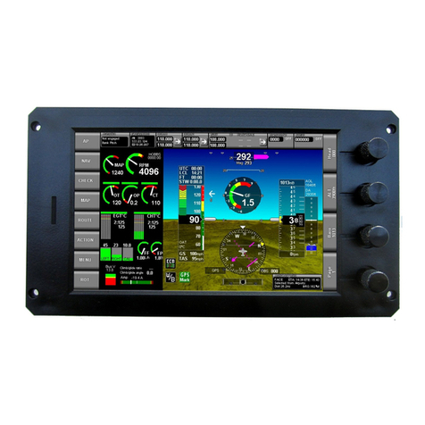
MGL Avionics
MGL Avionics iEFIS Lite Getting started guide

Avidyne
Avidyne Entegra EX5000 installation manual
Avidyne
Avidyne Entegra EXP5000 Pilot's guide addendum

Dynon Avionics
Dynon Avionics EFIS-D10 installation guide

COBHAM
COBHAM S-TEC Twenty Pilot operating handbook
Digifly
Digifly Archimede Plus user manual
Flight Data Systems
Flight Data Systems HHMPI Operator's manual

BOMBARDIER
BOMBARDIER Primus 2000XP Pilot training guide
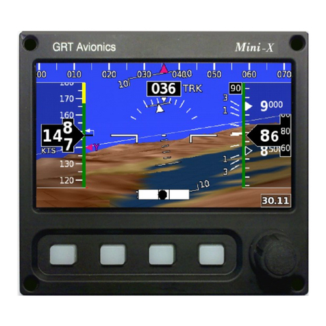
GRT Avionics
GRT Avionics Mini-X EFIS Installation & user manual
air avionics
air avionics ATD-11 installation manual
FLYelectronics
FLYelectronics MotoMonitor quick start guide

Propeller
Propeller AEROPOINTS user manual

