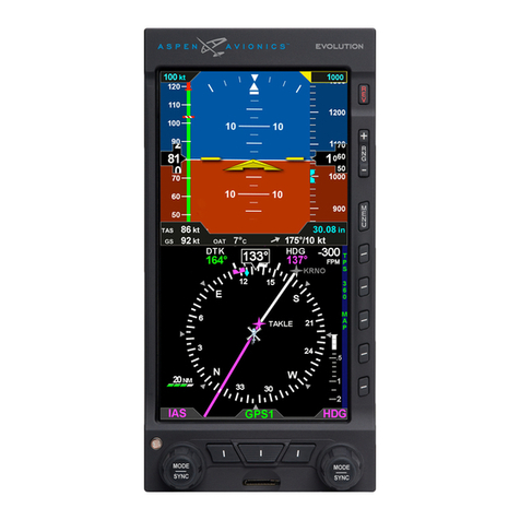
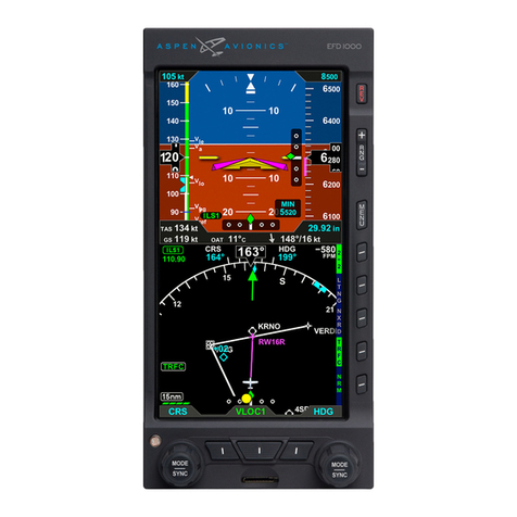
Aspen Avionics EFD1000 Dual EFI Manual

Evolution E5 Dual EFI
Pilot Guide


EFD1000 E5 Pilot’s Guide Page iii091-00086-001 ( )
Evolution E5 Dual EFI
Pilot Guide

EFD1000 E5 Pilot’s Guide
Page iv
REVISION DESCRIPTION of CHANGE
Initial Release

EFD1000 E5 Pilot’s Guide Page v091-00086-001 ( )
Table of Contents
Document Revisions ................................................................................ iv
Copyrights, Trademarks and Patents .................................................... ix
Approvals..................................................................................................... x
LIMITED WARRANTY Aspen Avionics, Inc. ............................................ xi
Conventions.............................................................................................. xiv
Covered Functionality..................................................................................................xiv
Terminology .......................................................................................................................xiv
Color Philosophy.............................................................................................................xvi
Warnings, Cautions, and Notes..............................................................................xvii
Example Graphics........................................................................................................ xviii
Pilot Familiarity............................................................................................................... xviii
Information Covered in this Pilot’s Guide ........................................................xix
Chapter 1
Welcome and Introduction....................................................... 1-1
1.1. System Overview..................................................................................................1-3
1.1.1. Electronic Flight Instrument (EFI)............................................. 1-4
1.1.2. Configuration Module (CM) ........................................................ 1-5
1.1.3. Analog Converter Unit (ACU)1.................................................... 1-5
1.1.4. Remote Sensor Module (RSM)................................................... 1-6
1.1.5. Evolution Databases........................................................................ 1-6
Chapter 2
Controls and Display ................................................................. 2-1
2.1. Controls & Display Orientation .......................................................................2-2
2.2. Controls......................................................................................................................2-4
2.2.1. Left and Right Knobs ...................................................................... 2-4
2.2.1.1. Left Knob Functions.......................................................... 2-5
2.2.1.2. Right Knob Functions ...................................................... 2-5
2.2.1.3. SYNC Function...........................................................2-6
2.2.1.4. Using the Knobs (Example) .......................................... 2-8
2.2.2. Navigation Source Select Buttons........................................... 2-8
2.2.3. Hot Keys................................................................................................2-10
2.2.4. Menu.......................................................................................................2-12
2.2.4.1. Using the Menus...............................................................2-12
2.2.4.2.Display Lighting ................................................................2-16
2.2.5. Range Buttons...................................................................................2-17
2.2.6. REV Button...........................................................................................2-17

EFD1000 E5 Pilot’s Guide
Page vi 091-00086-001 ( )
2.3. Display .....................................................................................................................2-18
2.3.1. Cleaning the Display Screen.....................................................2-19
2.3.2. Attitude Display................................................................................2-20
2.3.2.1. Attitude Director Indicator (ADI).............................2-22
2.3.2.2. Airspeed Tape and Bug .................................................2-23
2.3.2.3. Altitude Tape & Vertical Speed..................................2-24
2.3.3. Data Bar......................................................................................2-25
2.3.4. Navigation Display..........................................................................2-26
2.3.4.1. Numerical Direction Indicator
(Magnetic Compass).......................................................2-28
2.3.4.2. Course Pointer
and Course Deviation Indicator (CDI)1................2-30
2.3.4.3. Deviation Off-Scale Indication ............................................2-30
2.3.4.4. Auto Course Select..........................................................2-30
2.3.4.5. Rate of Turn Indicator....................................................2-31
2.3.4.6. Vertical Speed Indicator (VSI) ...................................2-32
Chapter 3
Flying the Dual EFI ..................................................................... 3-1
3.1. Quick Controls Overview.................................................................................3-3
3.2. Example Flight Scenario...................................................................................3-5
3.2.1. Pre-Departure (Startup) ................................................................. 3-6
3.2.2. Departure.............................................................................................3-13
3.2.3. Enroute ..................................................................................................3-15
3.3. Conclusion...............................................................................................3-17
Chapter 4
Reference Guide ......................................................................... 4-1
4.1. Air Data, Attitude and Heading Reference System (ADAHRS)..4-2
4.1.1. Attitude.................................................................................................... 4-3
4.1.2. Pitot Obstruction Monitor............................................................ 4-4
4.1.3. Heading................................................................................................... 4-5
4.1.4. Free Gyro Mode.................................................................................. 4-6
4.1.5. Degraded ADAHRS Performance............................................. 4-7
4.2. Attitude Display.....................................................................................................4-8
4.2.1. Attitude Indicator .............................................................................. 4-8
4.2.1.1. Roll Scale.................................................................................. 4-9
4.2.1.2. Pitch Scale............................................................................... 4-9
4.2.1.3. Slip/Skid Indicator.............................................................. 4-9
4.2.2. Airspeed Indicator...........................................................................4-10
4.2.2.1. Selected Airspeed ...........................................................4-12
4.2.2.2. Airspeed Display ...............................................................4-13
4.2.3. Altimeter ...............................................................................................4-14
4.2.3.1. Barometric Units of Measure .....................................4-15
4.2.3.2. Selected Altitude Field..................................................4-17
4.2.3.3. Altitude Display .................................................................4-18

4.3. Data Bar ...................................................................................................................4-19
4.3.1. Ground Speed ...................................................................................4-19
4.3.2. Barometric Pressure Setting Display.....................................4-19
4.4. Navigation Display............................................................................................4-20
4.4.1. Compass ..............................................................................................4-21
4.4.1.1. 360° Compass Mode.......................................................4-21
4.4.1.2. ARC Compass Mode .......................................................4-21
4.4.2. Course Pointer1................................................................................4-23
4.4.3. TO/FROM Indicator1.......................................................................4-24
4.4.4. Course Deviation Indicator and Scale1................................4-25
4.4.5. CDI Navigation Source..................................................................4-25
4.4.6. Auto Course ........................................................................................4-27
4.4.7. CDI Selected Course ......................................................................4-28
4.4.8. Heading Bug.......................................................................................4-29
4.4.9. Aircraft Heading Display..............................................................4-30
4.4.10. Rate of Turn Indicator.................................................................4-30
4.4.11. Ground Track Marker...................................................................4-31
4.4.12. GPS OBS Operation with a EFI and a Mechanical
Standby Nav Indicator...................................................................4-31
4.4.13. Course Pointer Operation with Integrated VOR/
Localizer/GPS Navigation Systems1.......................................4-31
4.5. Vertical Speed Indicator ................................................................................4-32
4.6. Autopilot Integration1.....................................................................................4-33
4.6.1. GPS Steering (GPSS)1......................................................................4-34
4.6.2. Typical Autopilot Operations1..................................................4-38
Chapter 5
Customizing the EFI ................................................................... 5-1
5.1. Menu Overview.....................................................................................................5-1
5.2. Configuring Vspeeds..........................................................................................5-5
5.3. LCD Brightness Control..................................................................................5-10
Chapter 6
Expanded Emergency and Abnormal Procedures ............... 6-1
6.1. Pitot/Static System Blockage ........................................................................6-2
6.1.1. Identifying and Handling Suspected Pitot
and/or Static System Failures ...................................................... 6-3
6.2. Frequent or Persistent CROSS CHECK ATTITUDE
Annunciation.......................................................................................................6-6
6.3. Difference Detected Between the E5 Dual EFI
and Mechanical Attitude Indicators..........................................................6-6
6.4. Abnormal Shutdown Procedure.................................................................6-7
6.5. Loss of Aircraft Electrical Power ..................................................................6-8
6.5.1. Overvoltage Protection.......................................................................6-9
6.6. Power Override...................................................................................................6-11
6.7. In-Flight AHRS Reset........................................................................................6-12
EFD1000 E5 Pilot’s Guide Page vii091-00086-001 ( )
EFD1000 E5 Pilot’s Guide
Page viii 091-00086-001 ( )
6.8. GPSS Operation, Annunciations, and Autopilot Modes............6-14
6.9. Warning, Caution, and Advisory Summary .......................................6-18
Chapter 7
Appendices.................................................................................. 7-1
7.1. Operating Limitations........................................................................................7-1
7.2. Software Versions and Serial Number .....................................................7-1
7.3. Specifications..........................................................................................................7-3
7.3.1. Primary Flight Display Unit (EFI)................................................ 7-3
7.3.2. Remote Sensor Module (RSM) .................................................. 7-5
7.3.3. Analog Converter Unit (ACU) ..................................................... 7-5
7.3.4. Operational Specifications........................................................... 7-6
7.4. Glossary ......................................................................................................................7-7
7.5. Index..........................................................................................................................7-10

EFD1000 E5 Pilot’s Guide Page ix091-00086-001 ( )
Copyrights, Trademarks and Patents
Copyright 2007-2018.
Aspen Avionics® is a registered trademark of Aspen Avionics, Inc.
Evolution™, EFD1000 Pro PFD™, EFD1000 MFD™, EFD500 MFD™,
EFD1000™, EFD500™, EFD 1000 VFR, Evolution E5 Dual EFI and the Aspen
Avionics logo are trademarks of Aspen Avionics, Inc. These trademarks
may not be used without the express permission of Aspen Avionics, Inc.
All rights reserved.
All other trademarks are the property of their respective companies. No
part of the Pilot’s Guide may be reproduced, copied, stored, transmitted,
or disseminated, for any reason, without the express written permission
of Aspen Avionics, Inc. Aspen Avionics hereby grants permission to
download a single copy, and any revision, of the Pilot’s Guide onto a
hard drive or other electronic storage medium for personal use, provided
that such electronic or printed copy of the Pilot’s Guide or revision must
contain the complete text of this copyright notice and provided further
that any unauthorized commercial distribution of the Pilot’s Guide or
revision hereto is strictly prohibited.
Avidyne® is a registered trademark of Avidyne Corporation; Bendix/
King® is a registered trademark of Honeywell; Garmin GTX™is a
trademark of Garmin International, Inc.; NavData® is a registered
trademark of Jeppesen, Inc.; SkyWatch® is a registered trademark of L-3
Communications; Stormscope® WX-500 is a registered trademark of
BFGoodrich Avionics Systems, Inc.; and XM is a registered trademark of
XM Satellite Radio, Inc.

EFD1000 E5 Pilot’s Guide
Page x 091-00086-001 ( )
Approvals
The FAA has approved the Aspen E5 under STC SA10822SC. Installation of
the E5 in a type-certificated airplane must be accomplished by a qualified
person in accordance with this STC.
Aspen Avionics, Inc.
5001 Indian School Road NE
Albuquerque, NM 87110
Phone: (505) 856-5034
Fax: (505) 314-5440
www.aspenavionics.com

EFD1000 E5 Pilot’s Guide Page xi091-00086-001 ( )
LIMITED WARRANTY
Aspen Avionics, Inc.
1. YOUR WARRANTY. Aspen Avionics, Inc. (“Aspen”) warrants
to you, the original purchaser, that its Products (if purchased from an
authorized dealer) will comply with applicable specifications (as set
forth in the owner’s manual) in all material respects and will be free from
material defects in workmanship or materials for a period of twenty-
four (24) months beginning with the date that the aircraft in which
the Product has been installed has been returned to service following
installation by an Aspen authorized dealer (“Return to Service Date”).
“Product” means new end equipment or hardware items, replaceable
units and components of those units.
2. YOUR REMEDY. During the term of this warranty, Aspen will
repair or replace, at its discretion, without charge (see Section 13 below
for information on covered transportation costs), any Product that does
not comply with the warranty of Section 1 above (a“Nonconforming
Product”), so long as the warranty claim is timely submitted and the
procedures in Section 14 (below) are followed. Aspen warrants repaired
and/or replacement items only for the unexpired portion of the original
warranty period, or, if the warranty has expired, for six months from
Aspen’s shipment of the repaired or replacement Product.
3. CONDITIONS TO COVERAGE. Aspen’s obligation under this
warranty is conditioned on your fulfillment of the obligation to:
A. Maintain records accurately reflecting operating time of and
maintenance performed on the Product,
B. Furnish proof sufficient to establish that the item is a
Nonconforming Product, and
C. Allow Aspen access to all relevant records in order to
substantiate your warranty claim.
4. EXCLUSIONS. The following are not covered by (and are
expressly excluded from) this warranty:
A. Normal wear and tear and the need for regular overhaul and
maintenance,
B. Exposure of the Product to temperature, environmental,
operating, or other conditions other than those prescribed in
the owner’s manual,
C. Failure to install or operate the Product as prescribed in the
owner’s manual or as Aspen otherwise directs,
D. Alterations or repairs made by anyone other than Aspen or its
authorized service center,
E. Maintenance, repair, installation, handling, transportation,
storage, operation (including, without limitation, operation
of the product’s software or host medium), or use which
is improper or otherwise does not comply with Aspen’s
instructions as set forth in the owner’s manual,

EFD1000 E5 Pilot’s Guide
Page xii 091-00086-001 ( )
F. Accident, contamination, damage from a foreign object or
weather conditions, abuse, misuse, neglect, or negligence,
G. Exposure of the product or the product’s host medium to any
computer virus or other intentionally disruptive, destructive, or
disabling computer code, and
H. Any damage precipitated by failure of a product Aspen has
supplied that is not under warranty or by any product supplied
by someone else.
5. INVALIDATION OF WARRANTY. This warranty is void if the
product is altered or repair is attempted or made by anyone other than
Aspen or its authorized service center.
6. WARRANTY CARD. The Return to Service Date must be
included in an accurately completed Aspen warranty application form
submitted by the installing authorized dealer within 30 days of the
Return to Service Date. The warranty application must be signed by the
authorized repairman who certifies that the equipment has been safely
and properly installed in accordance with all Aspen supplied technical
information and in accordance with all applicable FAA procedures and
requirements. The warranty application form must note the repairman’s
FAA certificate number to be valid. FAILURE TO COMPLETE AND RETURN
THE WARRANTY CARD MAY RESULT IN DENIAL OF WARRANTY CLAIMS.
MAKING CERTAIN THAT THE WARRANTY CARD IS COMPLETED, SIGNED,
AND RETURNED IS YOUR RESPONSIBILITY.
7. SOLE REMEDY. Aspen’s sole obligation, and your
exclusive remedy under this warranty, is limited to either the repair
or replacement, at Aspen’s option, of any Nonconforming Product as
provided herein.
8. EXCLUSIVE WARRANTY. THIS WARRANTY IS EXCLUSIVE
AND IN LIEU OF ALL OTHER WARRANTIES. THE IMPLIED WARRANTY
OF MERCHANTABILITY AND IMPLIED WARRANTY OF FITNESS FOR A
PARTICULAR PURPOSE, AS WELL AS ALL OTHER IMPLIED WARRANTIES
(STATUTORY OR OTHERWISE) EXPIRE AT THE END OF THE WARRANTY
PERIOD PRESCRIBED IN SECTION 1.
Some States do not allow limitations on how long an implied warranty
lasts, so the above limitation may not apply to you.
9. INCIDENTAL DAMAGES. ASPEN SHALL NOT UNDER ANY
CIRCUMSTANCES BE LIABLE FOR ANY SPECIAL, DIRECT, INDIRECT,
INCIDENTAL OR CONSEQUENTIAL LOSS OR DAMAGES OF ANY KIND
(INCLUDING WITHOUT LIMITATION: DAMAGES FOR LOSS OF PROFITS,
LOSS OF REVENUES, OR LOSS OF USE OR BUSINESS INTERRUPTION),
EVEN IF ASPEN HAS BEEN ADVISED OF THE POSSIBILITY OR CERTAINTY
OF THOSE DAMAGES OR IF ASPEN COULD HAVE REASONABLY
FORESEEN THOSE DAMAGES.
Some states do not allow the exclusion of incidental or consequential
damages, so the preceding limitations may not apply to you.
10. LIMITATION OF LIABILITY. ASPEN’S AGGREGATE LIABILITY
HEREUNDER, WHETHER BASED UPON CONTRACT, TORT (INCLUDING
NEGLIGENCE AND STRICT LIABILITY), INDEMNITY, OR OTHERWISE, WILL
NOT EXCEED THE PRICE PAID BY YOU FOR THE WARRANTED PRODUCT.
THE EXCLUSIONS OF TYPES OF DAMAGES CONTAINED HEREIN WILL BE
DEEMED INDEPENDENT OF, AND WILL SURVIVE, ANY FAILURE OF THE
ESSENTIAL PURPOSE OF ANY LIMITED REMEDY UNDER THE TERMS OF
ANY AGREEMENT.

EFD1000 E5 Pilot’s Guide Page xiii091-00086-001 ( )
11. EXTENSION OF WARRANTY. No extension of this warranty
will be binding upon Aspen unless set forth in writing and signed by
Aspen’s authorized representative.
12. DEALER WARRANTIES. Any express or implied warranty
or remedy in addition to or different from those stated herein that is
offered by a dealer (“Dealer Warranty”) will be the sole responsibility
of the dealer, who will be solely responsible for all liability, loss, cost,
damage, or expense arising out of or in connection with any such Dealer
Warranty. Although Aspen provides training and assistance to dealers,
it cannot control the installation of its Products by its dealers, which are
independent businesses not owned or controlled by Aspen.
13. TRANSPORTATION COSTS. Aspen will assume round
trip transportation costs for a Product determined by Aspen to be a
Nonconforming Product in an amount not to exceed normal (non
express) shipping charges within the continental United States. You
are responsible for all import/export fees, taxes, duties, customs,
documentation fees, clearance fees, and similar fees and charges.
You may contact Aspen to obtain a freight courier account number
for prepaid shipping of the return. If Aspen subsequently determines
that the Product is not a Nonconforming Product, that this warranty
is inapplicable, that the Product is out of warranty, that the defect or
malfunction is excluded from coverage, or that the warranty is invalid,
Aspen will invoice you for repair or replacement costs and the shipping
costs. Risk of loss or damage for any Product in transit will be borne by
the party initiating the transportation.
14. WARRANTY PROCEDURE. If you require warranty service,
you may contact your local Aspen Authorized Dealer or you may
contact Aspen directly as described below. An original or copy of
the sales receipt from the original Aspen Authorized dealer will be
required to obtain any warranty service. You may contact Aspen for
warranty service directly by calling Aspen Customer Service at (505)
856-5034; by writing to Aspen Customer Service Department, Aspen
Avionics, Inc., 5001 Indian School Road NE, Albuquerque, New Mexico,
87110; or by visiting the Aspen Website at
http://www.aspenavionics.com.
This warranty gives you specific legal rights, and you may also have other
rights, which vary from State to State.

Conventions
The following conventions, functionality, terminology, color philosophy,
and definitions are used in this manual and on the EFD1000 Dual EFI.
Covered Functionality
This guide covers all the functions available in the Evolution E5 Dual EFI.
Terminology
The term “EFI”, is used throughout this Pilot’s Guide and refers to the Evolution E5
Dual EFI.
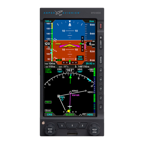
Figure 1 shows a typical EFI display. This guide uses the terminology listed in
Table 1 when referring to specific parts of the EFI and Chapter 4 provides an
in-depth discussion and step-by-step instructions for all the available functionality.
EFD1000 E5 Pilot’s Guide
Page xiv 091-00086-001 ( )

EFD1000 E5 Pilot’s Guide Page xv091-00086-001 ( )
Term Example
Buttons REV Button, Range Buttons, MENU Button
Hot Keys / Menu Keys Five keys on the lower right of the display
Buttons CDI Navigation Source Select Button (Center Button)
Knobs Left (CRS) Knob, Right (HDG) Knob
Navigation Display
Data Bar
Airspeed, attitude, altitude display
Table 1
EFD1000 PFD Display, Knobs , Buttons, and Keys
Figure 1
EFI Display, Knobs , Buttons, and Keys

Color Philosophy
Table 2 provides the general operational philosophy of color usage on the EFI display.
COLOR PURPOSE COLOR PURPOSE
RED
Used to indicate flight envelope and system limits, and
for warning annunciations that require immediate pilot
recognition and which may require immediate pilot
correction or compensatory action. Red is used to indicate
Data Link Weather precipitation areas.
GREEN
Used for navigation information or mode data related to
or provided by the navigation source currently selected for
display on the Course Deviation Indicator (CDI) (i.e., navigation
deviations, equipment operating state, waypoint information).
Green is also used to indicate Data Link Weather precipitation
areas and the status of user controls (i.e., ON, enabled, or
active).
AMBER
Used to indicate abnormal information sources, and for
caution information that requires immediate pilot awareness
and for which subsequent pilot action may be required.
Amber is used to indicate Data Link Weather precipitation
areas.
WHITE Used to show primary flight data (e.g., IAS, ALT, HDG), scales,
and Menu items that are selectable for editing.
MAGENTA
Used for pilot-selectable references (bugs) enabled for editing,
for depicting the active GPS navigation leg on a moving map
display, and for depicting the flight director bar.
GR AY Used to show supplemental flight data, and for Hot Key and
Menu legends that are OFF, disabled, or inactive.
CYAN
Used to indicate editable values that are not currently selected
for editing. CYAN is also used to display bearing pointers,
proximity and other traffic icons, and GPS track marker.
BLUE Used to indicate the sky and Data Link Weather precipitation
areas.
BROWN Used to indicate the ground.
Table 2
Color Guide
EFD1000 E5 Pilot’s Guide
Page xvi 091-00086-001 ( )

EFD1000 E5 Pilot’s Guide Page xvii091-00086-001 ( )
Warnings, Cautions, and Notes
Where applicable warnings, cautions, and notes are used in this manual. Aspen Avionics
uses the following icons and definitions (Table 3).
Icon Definition
Warning
Emphasizes a crucial operating or maintenance procedure, which, if not
strictly observed, could result in injury to, or death of, personnel or long
term health hazards.
Indicates a hazard that may require immediate corrective action.
Caution
Indicates an essential operating or maintenance procedure, which,
if not strictly observed, could result in damage to, or destruction of,
equipment.
Indicates the possible need for future corrective action.
Note
Highlights an important operating or maintenance procedure,
condition, or statement.
Safe operation.
Table 3
Warning, Caution, and Note

Example Graphics
The example graphics and screen shots used throughout this Pilot’s Guide are provided
for reference only and are taken from a simulated flight. They should not be used for
actual flights.
Pilot Familiarity
While the E5 is reasonably intuitive and easy to use, some familiarity with E5 Dual
Electronic Flight Instrument required. Aspen Avionics strongly recommends that new
users get some dual instruction from an experienced instrument CFI, and spend some
time becoming familiar with the E5 Dual EFI.
E5 Overview
The E5 system is built around the EFD 1000 which replaces the Attitude Indicator and
Directional Gyro of your six primary flight instruments. The E5 Dual EFI is IFR capable
with limitations.
E5 / MFD Compatibility
Aspen offers an MFD 500 and MFD 1000. The E5 is not compatible with our MFDs. In
order to integrate with either MFD you must first upgrade the E5 to a PFD Pro.
EFD1000 E5 Pilot’s Guide
Page xviii 091-00086-001 ( )
EFD1000 E5 Pilot’s Guide Page xix091-00086-001 REV ( )
Information Covered in this Pilot’s Guide
This Pilot’s Guide covers all the features and options available in the E5 Dual EFI.
E5 Dual EFI Options:
- ACU (Analog converter unit) used to connect auto pilots, analog nav sources, legacy
GPS.
If there is a chance you may wish to upgrade to a Pro in the future including the
optional ACU with the original E5 install is highly recommended. Including it in the
initial install eliminates the need to open up the aircraft during a E5 to PRO upgrade.
If an ACU was part of the initial E5 installation the VFR to PRO upgrade is a simple
software upgrade.
The E5 to PRO software upgrade converts the E5 CDI to a HSI in both 360 compass
and arc modes, adds dual bearing pointers in 360 compass mode, vertical deviation
indicator, localizer deviation indicator, minimums (decision height) flight director and
Radio Altitude display input.

CHAPTER 1 WELCOME
EFD1000 E5 Pilot’s Guide
Page PB 091-00086-001 ( ) EFD1000 E5 Pilot’s Guide Page 1-1
091-00086-001 ( )
Chapter 1
Welcome and Introduction
Welcome to Aspen Avionics’Evolution Flight Display (EFD) System, the
most flexible, expandable, and upgradable Electronic Flight Instrument
available for general aviation aircraft. Designed to replace the attitude
indicator and directional gyro. This modularity and upgradability allows
the system to grow with you and your airplane, over time and affordably.
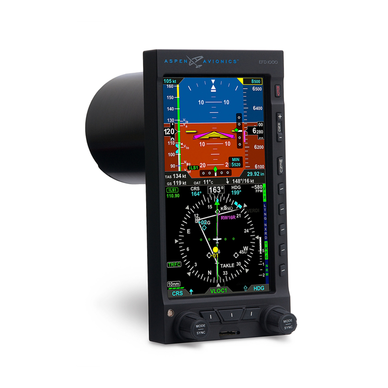
The EFD system is built around the E5 Dual EFI, which replaces a vertical pair of your six
primary flight instruments. The E5 has a bright, high-resolution, six-inch diagonal LCD
display, and a number of knobs, buttons, and keys the pilot uses to control the system.
The three-inch diameter, four-inch deep can on the back of the display slides into
existing panel cutouts (where the top mechanical instrument used to be)
(Figure 1-1).
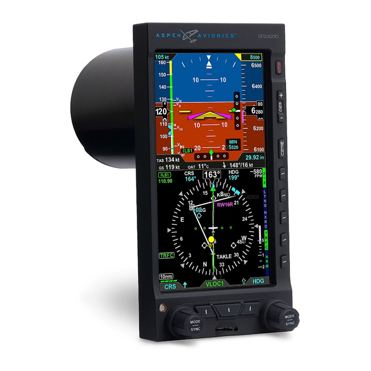
Figure 1-1
E5 Dual EFI Primary Flight Display Unit
This manual suits for next models
1
Table of contents
Other Aspen Avionics Avionic Display manuals

Aspen Avionics
Aspen Avionics Evolution EFD1000 PFD Manual

Aspen Avionics
Aspen Avionics Evolution EFD1000 PFD Manual

Aspen Avionics
Aspen Avionics AT300 Manual

Aspen Avionics
Aspen Avionics Evolution 1000 Pro/VFR PFD Manual

Aspen Avionics
Aspen Avionics Evolution EFD1000 PFD Technical specifications

Aspen Avionics
Aspen Avionics EFD1000H PFD Manual

Aspen Avionics
Aspen Avionics EFD1000 E5 User manual

Aspen Avionics
Aspen Avionics Evolution EFD1000 PFD Manual