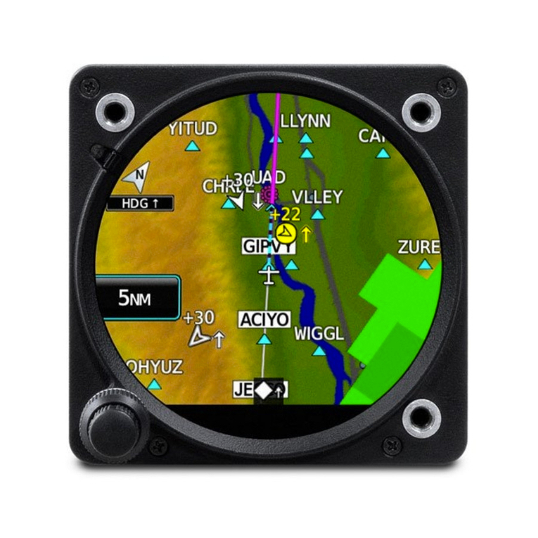
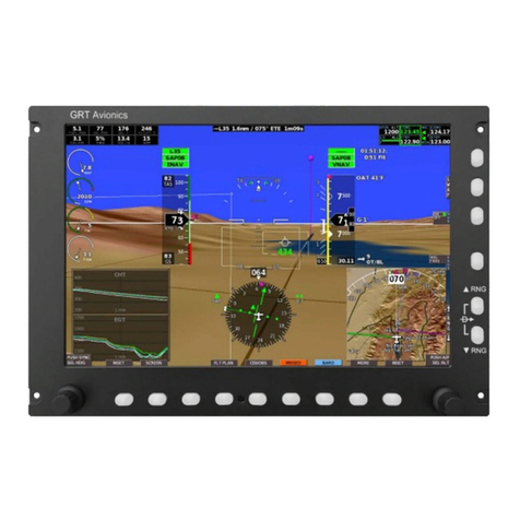
GRT Avionics Mini-X EFIS Instruction Manual

Mini-X EFIS
Installation, Setup, and User Manual
Revision A9
14-January-2020

Mini-X Installation, Setup & User Manual GRT Avionics
Revision A9 2
3133 Madison Ave. SE
Wyoming, MI 49548
(616) 245-7700
www.grtavionics.com
Copyright© 2014

Revision A9 3
GRT Avionics Mini-X Installation, Setup & User Manual
Manual
Revision Date Software
Revision Change Description
A 06-Jun-2014 1 Initial Release
A1 16-Jun-2014 1a Appendix, A.1.5 and A.1.6- Corrected and clarified AHRS and Air Data
Software update instructions.
A2 16-Jul-2014 1b
Added & clarified wiring options for Trig TT21/TT22 remote transponder,
Section 2.5
Added TT22 to list of choices for RS-232 serial ports, Section 2.6
A3
27-Aug-2014
1d
Added information about PFD navigation options (Waypoint Balloons,
Course Ribbons, and Enroute Highway-In-The-Sky), Section 5.9
Updated image of North-Up map presentation with compass rose,
Section 6.4.
Added information about the Synthetic Approach, Section 7.4
A4
29-Aug-2014
1d Fixed typographical errors in Section 4.6 and 4.7.
A5 11-Feb-2015 1d Improved Magnetometer installation and calibration instructions.
A6
24-Sep-2015
1d Added Angle-of-Attack installation and calibration instructions.
A7 23-Feb-2016 2
Backup-Battery Instructions added.
Added setting magnetometer orientation before fine calibration and
validation of magnetometer location.
A8
17-Apr-2017
1d AOA Installation and calibration restored. Magnetometer wiring
updated to show both possible sets of wire colors.
A9
Tuesday
January 14
2020
2Added section covering Graphical Engine Monitoring with GRT
Engine Information System.
Mini-X Manual Revision Notes

Mini-X Installation, Setup & User Manual GRT Avionics
Revision A9 4
Thank you for choosing GRT Avionics!
We hope you enjoy your new avionics system for many years to come.
Warranty & Return Policy
All GRT products include a 2-year warranty starting on the day the instrument is put into service (or
three years after purchase, whichever comes first) against manufacturer defect.
Please contact Tech Support before returning a display unit or component to GRT for repair or
warranty work. Many issues are installation or software-related and can be resolved over the phone,
saving time and expense. Please keep in mind that the minimum bench charge for EFIS units is $100.
All returns for repair or upgrade must be accompanied by a Service Request Form, downloadable
from the GRT website Support section.
Satisfaction Guarantee– If for any reason you are unhappy with your GRT product, you may return
it for a refund anytime during the first 60 days you own it. Some restrictions apply. Please call GRT
Tech Support before returning any system or component.
Technical Support
Our tech support staff has many years of real-world experience installing, flying and
troubleshooting GRT equipment in many different types of aircraft. We are here to make sure your
project succeeds.
Tech Support Hours
Monday-Friday 9:00 AM-12:00 PM and 1:00 PM -4:00 PM Eastern Time
(616) 245-7700 (EFIS Support phone menu option) or [email protected]
24-Hour Tech Support: The GRT Online Forum
Many questions may already have answers posted in our Online User Forum. Join today for free!
www.grtavionics.com/forum

Mini-X Installation, Setup & User Manual GRT Avionics
Revision A9 5
Contents
Mini-X EFIS.................................................................................................................1
Warranty & Return Policy...................................................................................................................4
1.1 About the Mini-X........................................................................................................................8
1.2 Tools & References for Installation............................................................................................8
1.3 Mini System Requirements........................................................................................................8
1.4 AHRS Specifications and Limitations........................................................................................9
1.5 Basic Controls of the Mini........................................................................................................11
2.1 Mini-X Connector Definition....................................................................................................15
2.2 General Wiring Guidelines.....................................................................................................17
2.3 Power Connections..................................................................................................................17
2.4 Autopilot Source Switch (Optional).........................................................................................18
2.5 Magnetometer Wiring (Optional/Recommended) .............................................................18
2.6 Inter-Display Communication................................................................................................19
2.7 Trig TT21/TT22 Transponder Interface......................................................................................20
2.8 General Serial Port Wiring Information...................................................................................21
3.1 Placement of the Mini on the Instrument Panel ...................................................................22
3.2 Mounting Hardware................................................................................................................22
3.3 Pitot/Static Connections..........................................................................................................22
3.4 Cooling Considerations...........................................................................................................22
3.5 Remote Magnetometer Installation (Optional) ....................................................................23
4.1 Boot-Up Check.........................................................................................................................24

Mini-X Installation, Setup & User Manual GRT Avionics
Revision A9 6
4.2 Explore the Set Menu Pages...................................................................................................24
4.3 Set Up Your General Preferences...........................................................................................25
4.4 Set Instrument Orientation.......................................................................................................26
4.5 External Magnetometer Location Validation .......................................................................27
4.6 Set Final Magnetometer and Instrument Orientation...........................................................28
4.7 Fine Magnetometer Calibration Procedure..........................................................................28
4.8 Altimeter Calibration...............................................................................................................32
4.9 Full Altimeter Calibration – Using Air Data Test Set................................................................33
4.10 Airspeed and Wind Calibration............................................................................................35
4.11 Angle of Attack (AOA) Installation and Calibration ...........................................................37
5.1 Primary Flight Display Overview.............................................................................................39
5.2 Airspeed Tape..........................................................................................................................40
5.3 Altimeter Tape...........................................................................................................................41
5.4 Vertical Speed Indicator.........................................................................................................43
5.5 Track/Heading Indicator..........................................................................................................43
5.6 Attitude Indicator/Artificial Horizon........................................................................................45
5.7 Flight Path Marker....................................................................................................................47
5.8 G-Meter.....................................................................................................................................47
5.9.7 Enroute HITS...........................................................................................................................52
6.1 Moving Map Overview............................................................................................................53
6.2 Moving Map Database ..........................................................................................................54
6.3 Map Screen Setup & Customization- Setup Menu................................................................54

Mini-X Installation, Setup & User Manual GRT Avionics
Revision A9 7
6.4 In-Flight Map Setup..................................................................................................................56
6.5 Map Selection Tool..................................................................................................................58
7.1 GPS CDI Bar..............................................................................................................................59
7.2 Flight Planning with the Mini....................................................................................................59
7.3 Airport/Facilities Information & Radio Tuning.........................................................................65
7.4 Synthetic Approach (SAP)........................................................................................................66
8.1 Autopilot....................................................................................................................................68
8.2 Trig TT22 Transponder..............................................................................................................69
8.3 Graphical Engine Monitoring with the EIS...............................................................................71
8.4 Data Recording .......................................................................................................................85
A.1 Updating Mini Software...........................................................................................................91
A.2 Backup Battery Operation......................................................................................................94

Mini-X Installation, Setup & User Manual GRT Avionics
Revision A9 8
Section 1: Introduction
1.1 About the Mini-X
We designed the Mini with two main goals in mind: A small, lightweight, economical VFR EFIS
system for LSA and light kitplanes, and an affordable, high-quality backup to larger EFIS systems
for IFR operations. The Mini utilizes the same pilot interface as the popular Horizon and Sport
series; If you already use GRT avionics for your primary flight display, you will not have to remember
a different brand’s “buttonology” in an IFR emergency. The Mini has a built-in GPS for navigation,
so you will always know where you are.
In addition to the basic backup flight instruments, all models of the Mini can also serve as a serial
altitude encoder for any modern transponder, and serve as a control head for a remote Trig TT22
transponder. To top it off, the brilliant 1200-nit, high-resolution display shared by all three Mini
models ensures great visibility in all lighting conditions.
1.2 Tools & References for Installation
In addition to basic mechanical hand tools, a D-sub pin crimper is required in most installations.
A basic 4-way indent crimper is available from SteinAir for less than $35. We supply a few loose
male and female pins with your wiring harness, and we have them available for sale if you need
more.
If you are new to electrical systems and wiring, we highly recommend reading
by Bob Nuckolls. This book has been around for almost 30 years and covers everything
a homebuilder needs to know about how electrical systems work, how to design them, and how
to build them. There are also numerous online video tutorials by EAA, SteinAir and others in the
experimental aircraft community on wiring technique and electrical system design.
1.3 Mini System Requirements
The Mini utilizes the following systems for operation:
�Aircraft Power (12- or 28-volt system) - 0.25 Amp current draw at full brightness
�Pitot/static connection for flight instrumentation
�Built-in GPS with a remote “puck” antenna which must be within view of the sky at all times.
�Optional remote magnetometer is required for magnetic heading information and AHRS
independent of GPS track– see Section 1.4 for more information.
Revision A9 9
GRT Avionics Mini-X Installation, Setup & User Manual
1.4 AHRS Specifications and Limitations
�Maximum Angular Rate: 250 deg/sec
�Maximum G-Limit : 4G for unlimited time, 10G for up to 20 seconds. G-limit affects accuracy of
the readout, but exceeding it will not damage the instrument.
�Ambient Temperature Range for full accuracy: -10°F to +150°F
�Airspeed Range : 30-335 mph IAS (stock AHRS) or 50-600 mph IAS (High-Airspeed version)
�Altimeter Range : -2000 to +40,000 feet
�Magnetometer Type: Internal (Mini-B and stock Mini-X) or External remote (Mini-AP and optional
for Mini-X). When the External magnetometer is installed, it overrides the Internal, which is then
used only in the unlikely event of failure of the remote unit.
1.4.1 Mini-X AHRS and Loss of GPS Data
Normal Operation
Attitude data will be full accuracy when valid external magnetometer data or GPS ground track
data is available. If no valid external magnetometer is available, and the GPS ground track data is
lost (because the airplane is moving less than 4 mph, or the GPS is not able to provide position
data), and the AHRS will attempt to use its internal magnetometer. If the internal magnetometer
is too inaccurate due to magnetic disturbances near the instrument, the ground track display on
the PFD screen will show dashes. The AHRS will provide full accuracy attitude information for at
least 5 minutes.
CAUTION: If the EFIS is unable to provide any heading or track data (the heading/ground track
display on the PFD screen is shown as dashes) for extended periods of time (more than 5 minutes)
the attitude data could become less accurate.

Mini-X Installation, Setup & User Manual GRT Avionics
Revision A9 10
Figure 1-1: Mini Dimensional Drawing (all models)
GRT Mini
01-Mar-2014
Notes:
�Cutout dimensions 4.15” x 3.30”
�Unit is centered within the cutout.
�Mounting screws are #4
�Mounting bolt pattern is centered on
bezel outline.

Revision A9 11
GRT Avionics Mini-X Installation, Setup & User Manual
1.5 Basic Controls of the Mini
The Mini has a single knob that can be pressed and turned, as well as four buttons. The buttons
are referred to as “softkeys” because their functions change as screen views and menus change.
Each button and knob has a label that defines its function. If there is no label present, the button
has no function on that particular screen. When the softkey labels are not visible, press any button
to make the labels appear. You can define how long the labels are displayed between button
presses– refer to Section 4.3, General Preferences, for more information.
1.5.1 Overview of Pages & Softkeys
The Mini-X has a Primary Flight Display page, a Flight Plan entry page and the Set Menu. When
equipped with the Moving Map option, it also includes a Moving Map page group.
1.5.2 Primary Flight Display Softkeys
1. Press any button to display the PFD Level 1 Softkeys shown below. The softkeys may be
displayed in a different order depending upon your software version and equipment
connected to the Mini. Use this section as a general guide to learn the functions of the softkeys.
Flight Plan
Entry Page
Moving
Map
(optional)
Screen
Dimmer
or Trans-
ponder
Turn to adjust Altimeter Setting
Press for Autopilot
More
items…

Mini-X Installation, Setup & User Manual GRT Avionics
Revision A9 12
PFD Level 2 Softkeys (typical)
Choose
Navigation
Source
Synthetic
Vision
Display
Options
Settings
Main Menu
Turn to adjust Altimeter Setting
Press for Autopilot
PFD Level 3 Softkeys (typical)
Error or
Warning
Details
Manually
Record or
Play Demo
File
Press when
finished with
softkeys
Turn to adjust Altimeter Setting
Press for Autopilot
More
items…

Revision A9 13
GRT Avionics Mini-X Installation, Setup & User Manual
1.5.3 Moving Map Softkey Functions (Optional)
1. Press the MAP softkey to display the Moving Map page.
Primary
Flight
Display
Cycle thru
map views
& HSI
Screen
Dimmer
or Trans-
ponder
Turn to adjust map range
Press once for Heading Bug
Press again for Map Selection Tool
cursor and Nearest selection softkeys
Map Level 2 Softkeys (typical)
Choose
Map
Shading
Choose
Fixes to
Display
Choose
Nav
Source
Turn to adjust map range
Press once for Heading Bug
Press again for Map Selection Tool
cursor and Nearest selection softkeys
More
items…
More
items…

Mini-X Installation, Setup & User Manual GRT Avionics
Revision A9 14
Map Level 3 Softkeys (typical)
Choose Lateral
Autopilot
Source
See objects
off the edge
of the map
View,
Create, Edit
Flight Plan
Nearest
Airport,
Weather Freq,
or Navaid
Settings
Main Menu
Turn to adjust map range
Press once for Heading Bug
Press again for Map Selection Tool
cursor and Nearest selection softkeys
Error or
Warning
Details
More
items…
Turn to adjust map range
Press once for Heading Bug
Press again for Map Selection Tool
cursor and Nearest selection softkeys
More
items…
Map Level 4 Softkeys (typical)
Map Level 5 Softkeys (typical)
Manually play
or record
demo file
Press when
finished with
sofkteys
Turn to adjust map range
Press once for Heading Bug
Press again for Map Selection Tool
cursor and Nearest selection softkeys

Revision A9 15
GRT Avionics Mini-X Installation, Setup & User Manual
Section 2: Wiring Considerations
2.1 Mini-X Connector Definition
The Mini-X comes with a female DB15 connector pre-wired with the most commonly used wires.
The optional remote magnetometer uses a DB9 connector and is connected to the Mini using the
pins defined below. The colors shown here correspond to the colors in the supplied wiring harness.
�The supplied wiring harness for the magnetometer is 20 feet long; all other wires are 4 feet long.
�The magnetometer serial output (Mag pin 9) may be shared with other GRT Avionics Mini-EFIS,
or the GADAHRS.
�The magnetometer, OAT, serial ports and Trig TT22 connections are all optional.
�OAT is required for true airspeed and density altitude calculations when the Mini does not have
a serial connection to a working GRT Horizon or Sport EFIS display unit.
�Use Trig TT22 A and B connections for control and encoder information for the TT22.
�Any of the serial port pairs can be used for a variety of connections, including connection to
another GRT display unit for limited data sharing, serial transponder or handheld GPS.
Magnetometer DB9
Pin No.
Mini DB15
Pin No.
Use Color
1 Serial 2 Out YEL
2 Serial 2 In YEL/WHT
3 Trig TT22 A
4 Trig TT22 B
5 Serial 1 Out GRN
6 Serial 1 In WHT/GRN
7 Ground BLK
8 Power in: 8-30V RED
8 (serial in) 9 Mag A/Serial 3 Out ORG
9 (serial out) 10 Mag B/Serial 3 In ORG/BLK or
WHT/BRN*
5 (mag power - must be
powered by Mini-X or an adaptive
AHRS)
11 Mag C BLU or WHT/RED*
1 (ground) 12 Mag D WHT/BLU or BLK*
13 Audio Output
14 Audio Ground
15 OAT GRY
*Two possible wire colors sets are possible. Pin 8, serial input, is optional,
an can only be connected to one Mini.

Mini-X Installation, Setup & User Manual GRT Avionics
Revision A9 16
GPS Antenna
Mini USB Port
DB15 Connector
(male)
Pitot Port Static Port
Figure 2-1: Rear Case View- Connector Placement

Revision A9 17
GRT Avionics Mini-X Installation, Setup & User Manual
2.2 General Wiring Guidelines
Wires that are certain to be used are pre-installed in the Mini cable assembly connectors. Optional
connections to the Mini are not installed in the D-sub connectors at the factory, however, colored
aviation-grade wires with pre-installed D-sub connector contacts are included for these connections.
The cable description diagram includes recommended wire colors for each connection to the Mini’s
components.
When routing the wiring, the following guidelines should be considered:
�Good practices for physical installation of the wiring should be followed, such as grommets where
wires pass through sheet metal, considering for chaffing and interference with moving
mechanisms, etc..
�Cable lengths should include enough extra length to allow for servicing the equipment. For
example, the cables which plug into the display unit should be long enough to allow them to be
connected to display unit with the display unit not installed in the instrument panel.
�In general, routing of the wiring is not critical, as the Mini is designed to be tolerant of the electrical
noise and other emissions typically found in aircraft. Some consideration should be given to avoid
routing wires near antennas, or other locations that could impart high levels of electromagnetic
signals on the wiring.
�The checkout procedures outlined in Section 4 must be completed to verify the Mini is not affected
by radio transmissions on any frequency.
�Consider the effects of individual component failures in the design of the system as a whole to
create redundancy where necessary.
2.3 Power Connections
Power Switch– No provision is included within the Mini for a power switch. If a power switch is
desired for the Mini, the +12V power should be controlled with the switch (not ground). It is
desirable to have the Mini power off during the engine start if the bus that powers it is used for
supplying power to the engine starter. Voltage drops during engine start can cause the Mini to
reboot. An installed backup battery will dampen this effect, but it is good wiring practice to isolate
EFIS avionics from the starter circuit.
Circuit Breaker– Power supplied to the Mini must pass through a fuse, circuit breaker, or system
such as a Vertical Power electronic circuit control system. It should be sized to allow at least 1/2
amp. At full brightness, the Mini consumes approximately 1/4 amp. The Mini contains internal
thermally-activated fuses to protect the equipment from internal electrical faults.

Mini-X Installation, Setup & User Manual GRT Avionics
Revision A9 18
Power Inputs- The Mini has one power input to be connected to the aircraft’s electrical system,
plus an option for an internal backup battery, which is charged through the main power input.
Voltage Monitor- The Mini monitors its power input and backup battery level. A warning will flash
to annunciate the loss of any power source that was provided and is expected to be working
according to the “General Setup” menu.
Ground Connection- The cable assembly provided includes 22 gauge wire for the ground return
of the Mini. This will result in a voltage drop of about 0.015 V/foot, which is acceptable for wire
lengths up to 10 feet.
2.4 Autopilot Source Switch (Optional)
If another GRT EFIS screen is used for the primary display, wire a switch into the instrument panel
to allow the Mini to be the selected autopilot source in case the main display should fail. In normal
operations, the autopilot control signals pass through the inter-display link, allowing either the
Mini or a primary GRT EFIS to control the autopilot when both screens are functioning, regardless
of the switch position. Refer to the GRT Autopilot wiring diagrams and installation/setup manual,
downloadable from the Support > Documentation > Autopilot section of our website, for more
information on wiring and setup of the GRT autopilot. (Note: In autopilot wiring & setup
documentation, the Mini is treated the same as any other type of GRT Display Unit. Pilot information
specific to Mini autopilot controls can be found in this manual.)
2.5 Magnetometer Wiring (Optional/Recommended)
The remote magnetometer must be placed in an area of the airplane with little or no
electromagnetic interference. The cable is 20 feet long and designed to reach out to the wingtip
or tail. Please refer to the magnetometer installation guidelines in Section 3.5 of this manual for
more information.

The magnetometer cable supplied with the Mini does not have a D-sub connector installed on the
magnetometer cable end. This makes it easier to route this cable through the airplane. After the
cable has been routed, the wires can be cut to length if desired. Install pins onto the ends of the
magnetometer wires. Note that they are the opposite orientation as the (Pins are not installed at
the GRT factory because experience has shown us that they are too easily damaged as they are
routed through the airplane.) Insert the indicated wire color into the appropriate D-sub connector
housing hole according to the Mini Connector Definitions diagram in Section 2.1.
The digital magnetometer serial output may be shared between any number of the Mini-X, Mini-AP,
and any Adaptive AHRS.

Revision A9 19
GRT Avionics Mini-X Installation, Setup & User Manual
2.6 Inter-Display Communication
GRT display units communicate between themselves so that most entries made during flight, such
as flight plan information, altimeter setting, and screen dimming, can be made from any display
unit and will be applied to all. Designate one serial port pair for the Mini and another for the GRT
display you want to connect it to and wire as shown below. Set the serial port rate to 19200 for
both screens. (Serial ports shown are just an example; any serial port can be used.)
GRT Horizon or
Sport EFIS Mini
Serial 2 RX
Serial 2 TX
Serial 1 RX
Serial 1 TX

Mini-X Installation, Setup & User Manual GRT Avionics
Revision A9 20
2.7 Trig TT21/TT22 Transponder Interface
The Mini is able to function as the control head for a Trig TT21 or TT22 remote transponder. Visit
the Trig Avionics website for the TT21/22 installation manual and wiring diagrams.
The Mini replaces the Trig TC20 control head. There are two options for wiring the Mini to the Trig.
Option 1: Wire the Trig to the Mini only using the Mini’s dedicated Trig port. This output has
an RS-485-based serial format that is compatible with the Trig controls. When the dedicated TT22
port is used, do not use the GRT Trig TT21/22 Serial Adapter, which is RS-232 based.
1. Wire the TRIG TT22 A and TRIG TT22 B pins on the Mini’s DB15 connector to either of the
Trig’s two TMAP sets as shown below.
2. Wire Pin 13 on the transponder directly to ground to allow the transponder to power up.
Option 2: Wire the Trig to both the Mini and one other GRT EFIS screen (Applicable only to
Sport SX and Horizon HX/HXr). Because Sport and Horizon screens do not have a dedicated
RS-485-based Trig port, you must attach a GRT Dual-Control Serial Adapter to the transponder,
which is then wired to an RS-232 serial port on both the Sport/Horizon and the Mini as shown
below. Wiring and setup information can be found in the GRT Trig TT21/22 Supplement,
downloadable from the GRT website under Support > Documentation > Equipment Supplements.
Follow all other instructions in the TT21/22 installation manual for wiring and setup. Instructions
for how to operate the transponder through the Mini pilot interface are found in Section 7 of this
manual.
Mini
Trig TT21/22
Remote Unit
TRIG TT22 A
TRIG TT22 B
TMAP1B
TMAP1A
Pin 13
Trig TT21/22
Remote Unit
Sport SX,
Horizon HX
or HXr
Mini
GRT Trig TT21/22
Dual-Control Adapter
Serial IN
Serial OUT
Serial IN
Serial OUT
Table of contents
Other GRT Avionics Avionic Display manuals