Benedini TBS Mini V2 User manual
Digital Multifunctional RC-Soundmodule
TBS Mini V2
Important notes about changes on the N W TBS Mini V2
!!! MUST B R AD !!!
Most important: Receiver power supply must be 4V to max. 6V !!!
This range is covered by most BEC receiver power supply.
New sound memory
- 16x larger → Enough for 24,8 minutes of sound
- „Erasing Flash“ lasts about 45s
- Filling the new sound memory completely takes about 45 minutes !
The NEW TBS Flash V4 software must be used for rogramming this TBS Mini
W digital audio amplifier on board
4Ohm and 8Ohm speakers can be used
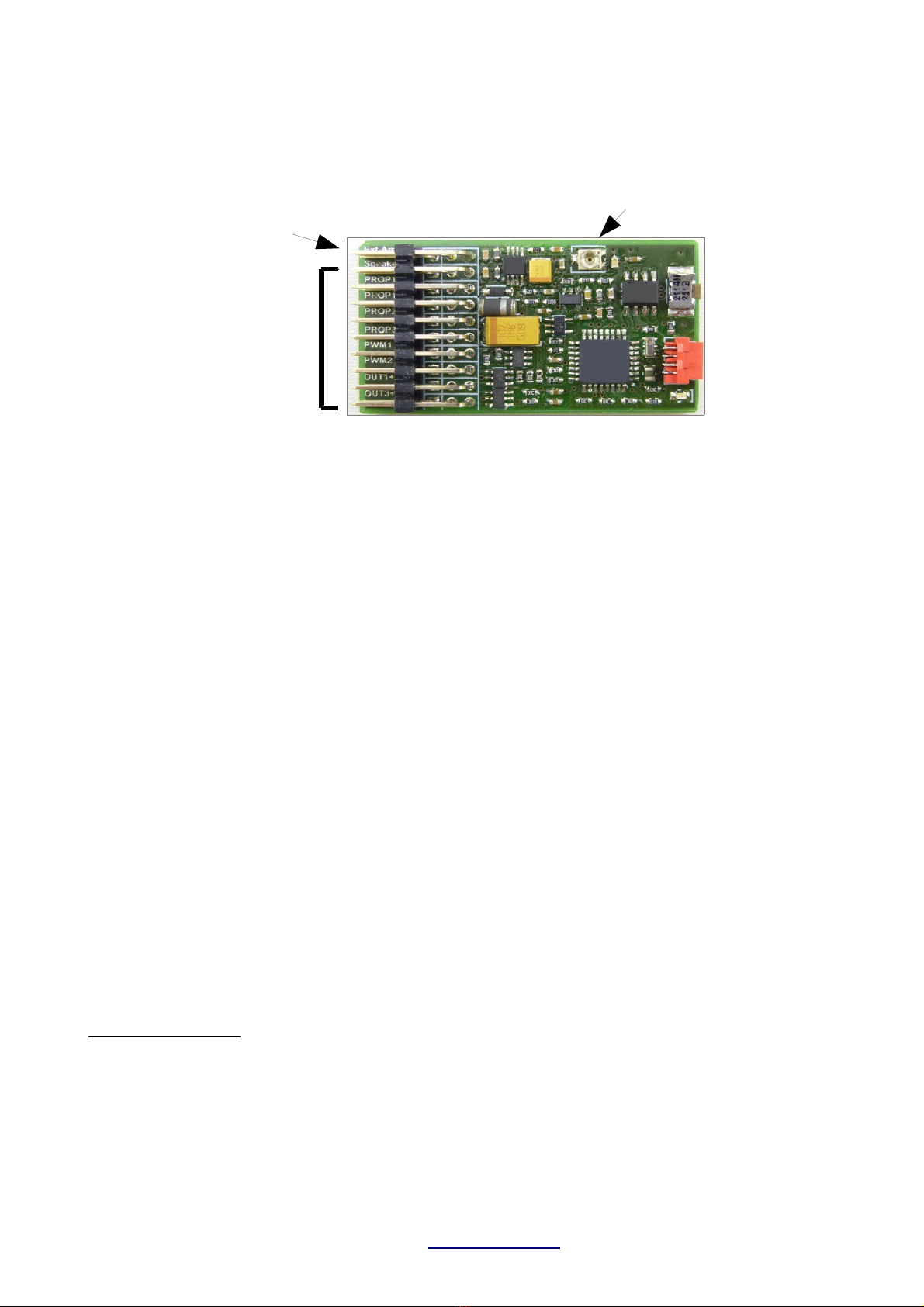
External amplifier connector on to → see icture above.
All other connectors remain unchanged and are located one osition lower than on the old TBS
Mini. Please see the TBS Mini V2 manual age 4 for all details.
The new connector allows direct usage of most 3rd arty am lifiers.
Hardware volume controller located on the Mini. Internal and ext. am lifier volume is set by this
controller. In arallel it is still ossible changing the volume by the transmitter (if the Mini
arameters settings are accordingly)
External am lifier and a s eaker connected directly to the TBS Mini can be used in arallel
Very important:
Connecting any rd party amplifier is FULLY on your OWN RISK regarding ANY damages
There will be no su ort for any 3rd arty am lifier.
TBS Mini V2, 11/2018 www.benedini.de Page 1 of 13
New connector:
External am lifier
Unchanged connectors
(same as old TBS Mini V1)
Volume

Manual
Digital Multifunctional RC-Soundunit
TBS Mini V2
Set control mode at delivery
O Encoder (PROP3 O Direct sound selection (PROP2
-> Page 8 -> Page 9
O Indirect sound selection (PROP3 O Autostart
-> Page 10 -> Page 11
O OpenPanzer Configuration -> see www.openpanzer.org
Loaded sound: _________________________________________________
Flashing output: O None O Out1 O Out2 O Out3 O Out4
Comment: ________________________________________________________
________________________________________________________
TBS Flash version: O Version 1 O Version 4
TBS Mini V2, 11/2018 www.benedini.de Page 2 of 13

1. Features
The TBS Mini is develo ed for all kind of RC controlled models, f.e. air lanes, helico ters,
tanks, trucks, cars, shi s, … . A large collection of original sound records is available.
New features of the TBS Mini V2:
- Onboard 3W digital audio am lifier for 4 and 8 Ohm s eakers
- Volume control on board
- Easy connection of external am lifier modules
- Watch the limited supply voltage range of max. 6V (= receiver su ly voltage)
Fully customer rogrammable. Your own sounds can be loaded!
Large sound library of original recordings available. Please check www.benedini.de
Sound quality 22KHz, 8Bit, Mono
Ca ability to lay two sounds simultaneously (engine and one s ecial sound)
16Mbit sound memory, enough for 93sec. at 22KHz
Internal am lifier with 3W at 4 Ohm s eaker
External high ower am lifiers available to meet different model requirements.
Remote (de ending on control mode) or local volume control
U to 6 switching out uts
- Can be triggered by a sound (f.e. Muzzle flashing) or inde endently (universal switching)
- Switching-, momentary- or flashing mode ossible
Only one ro ortional channel necessary to control all functions of the unit.
S eed signal derived from the receiver. This allows combination with brushless or brushed
motors.
Small and low weight
USB rogramming cable available (o tional)
Totally rogrammable by the free of charge software “TBS Flash”:
- You can load your own sounds or any of the Benedini sounds available at
www.benedini.de
–Firmware u date! This means you have always the latest software at you unit.
–FREE OF CHARGE sound libraries available at www.benedini.de
The TBS Mini soundunit can be fully configured by the o tional rogramming cable and a
common PC. Please see the se arate manual for the TBS Flash software.
The unit can be controlled by a s are ro ortional channel by one of the following modes:
12- osition encoder (combination of rotary switch and ush button)
3- osition switch for direct sound selection
3- osition switch for indirect sound selection
Autostart (NO additional ro ortional s are channel necessary in this mode)
→ See detailed descri tion of each mode in the according cha ter of this manual.
TBS Mini V2, 11/2018 www.benedini.de Page 3 of 13
2. Connection
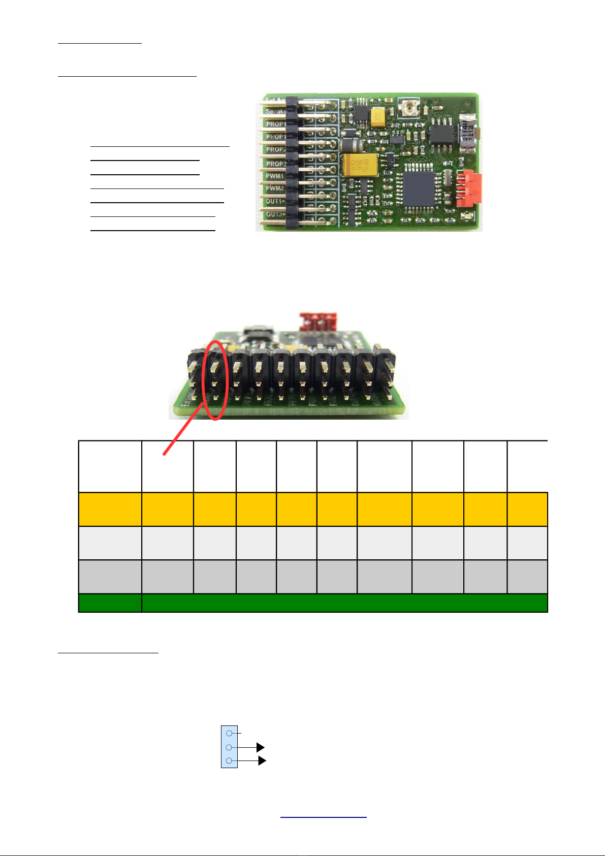
Plugs (from top to bottom)
1. External am lifier (o tional)
2. Seaker
3. Pro 1 Input (S eed IN)
4. Pro 1 Output (S eed OUT)
5. Pro 2 In ut (o tional)
6. Pro 3 In ut (o tional)
7. PWM1 (Servo 1 or Out 10)
8. PWM2 (Servo 2 or Out 11)
9. Out 1+2 switching out ut
10. Out 3+4 switching out ut
Watch plug orientation
!!! Signal lead is always on TOP (orange or white) !!!
xt.
Amplifier Speaker PROP
1 In
PROP
1 Out
PROP
2 In
PROP
3 In
PWM 1
(OUT 10
PWM 2
(OUT 11
OUT
1+2
OUT
3+4
NC Speaker
Plus
Signal
(In
Signal
(Out
Signal
(In
Signal
(In
Signal
(Out
Signal
(Out
OUT 2
(Minus
OUT 4
(Minus
Signal Speaker.
Minus Plus Plus Plus Plus Plus Plus Plus Plus
Minus Frei Minus Minus Minus Minus Minus Minus Out 1
(Minus
OUT3
(Minus
External amplifier:
Most commercial am lifier modules with high im edance in ut can be connected directly.
Volume is set on the TBS Mini. If a common servo cable is used for making the audio connection,
RED is signal and BROWN is ground. DO NOT CONNECT A SPEAKER TO THIS PORT !!!
TBS Mini V2, 11/2018 www.benedini.de Page 4 of 13
Learn Button
Prog. Cable
Top: Signal (orange)
Center: Power (red)
Bottom: GND (black)
TBS Mini
Free
Audio Signal
GND
External amplifier
Audio In (red)
Groung (brown)

Remote volume control
If “Encoder” or “Indirect sound selection” control mode is used, the volume can be set remotely
from the transmitter (If the TBS Mini arameters are set accordingly!)
Standard setting: Function Nr. 11: Volume u Nr. 12: Volume down
O eration:
Select the desired function and KEEP it triggered → Volume changes constantly
If the desired volume is reached, release the trigger button.
Speaker:
If the s eaker is connected by a common servo cable, use the ORANGE (+ s eaker)
and RED (- speaker) lead. Brown is not used.
4 or 8 ohm s eakers can be used. Make sure not using the am lifier connector of the TBS Mini !
Prop 1 (Receiver speed channel)
Pro 1 is available twice, both are identical. The receiver s eed channel is connected to one of them,
the ESC can be connected to the second one.
Note:
If a ESC with integrated BEC is used for owering the receiver, it is highly recommended using a
se arate servo y-cable for connecting the receiver s eed channel to the ESC and Pro 1 of the TBS
Mini. This ensures that the receiver su ly current (coming from the ESC) flows directly to the
receiver and not through the sound unit.
Prop2 (optional)
This multi functional receiver in ut can be configured to the following:
- Second s eed channel in ut for tracked models
- Control in ut for selecting the desired sound to lay
- Sensor in ut for load de endant sound adjustment
→ Please see details on the TBS Flash manual.
Prop
Receiver in ut for selecting the desired sound to lay.
PWM 1
Servo1 signal or switching out ut (Out10)
→ Please see details on the TBS Flash manual.
PWM 2
Servo2 signal or switching out ut (Out11)
→ Please see details on the TBS Flash manual.
Out 1-4
Universal switching out uts
Hints to switching outputs Out 1-4, Out 10 and Out 11
The desired out uts must be configured by the TBS Flash software according to the desired
functionality (switching, momentary, flashing). This can be done by the TBS Flash software and the
o tional USB rogramming cable.
!! All outputs are switching to NEGATIVE of the receiver supply voltage !!
PLUS is available at the centre contacts of each connector → See connection icture above.
Out 10 is located at the signal in of PWM1 (u er in)
Out 11 is located at the signal in of PWM2 (u er in)
TBS Mini V2, 11/2018 www.benedini.de Page 5 of 13

2.1. Installation schematic (→ See also last page )
TBS Mini V2, 11/2018 www.benedini.de Page 6 of 13
Z
Z
+
+
-
-
OUT 2
OUT 1
Z
Z
+
+
-
-
OUT 4
OUT 3
Speed
Optional
Control
External
amplifier
(optional
ESC + BEC
Main Battery
Universal switching outputs
Resistors for LEDs
Programming by USB Prog.cable
(Sound und Parameter
optional
Receiver
Speaker
TBS Mini V2
Orange
Red
Black
Orange
Red
Black
First setup
Im ortant:
! Watch safety aspects at the end of this manual before first flight !
The TBS Mini is delivered full rogrammed and ready to run, according to your order.
!! For the final setup YOU must teach it to your radio !!
The control mode set at delivery is indicated at the first age of this manual.
Please see the following cha ters how to teach the Mini according to the set control mode:
Encoder: Page: 5
Direct sound selection: Page: 7
Indirect sound selection: Page: 8
Autostart: Page: 9
!! Any configuration changes should be made AFTER the first setup was successfully !!
. Control modes
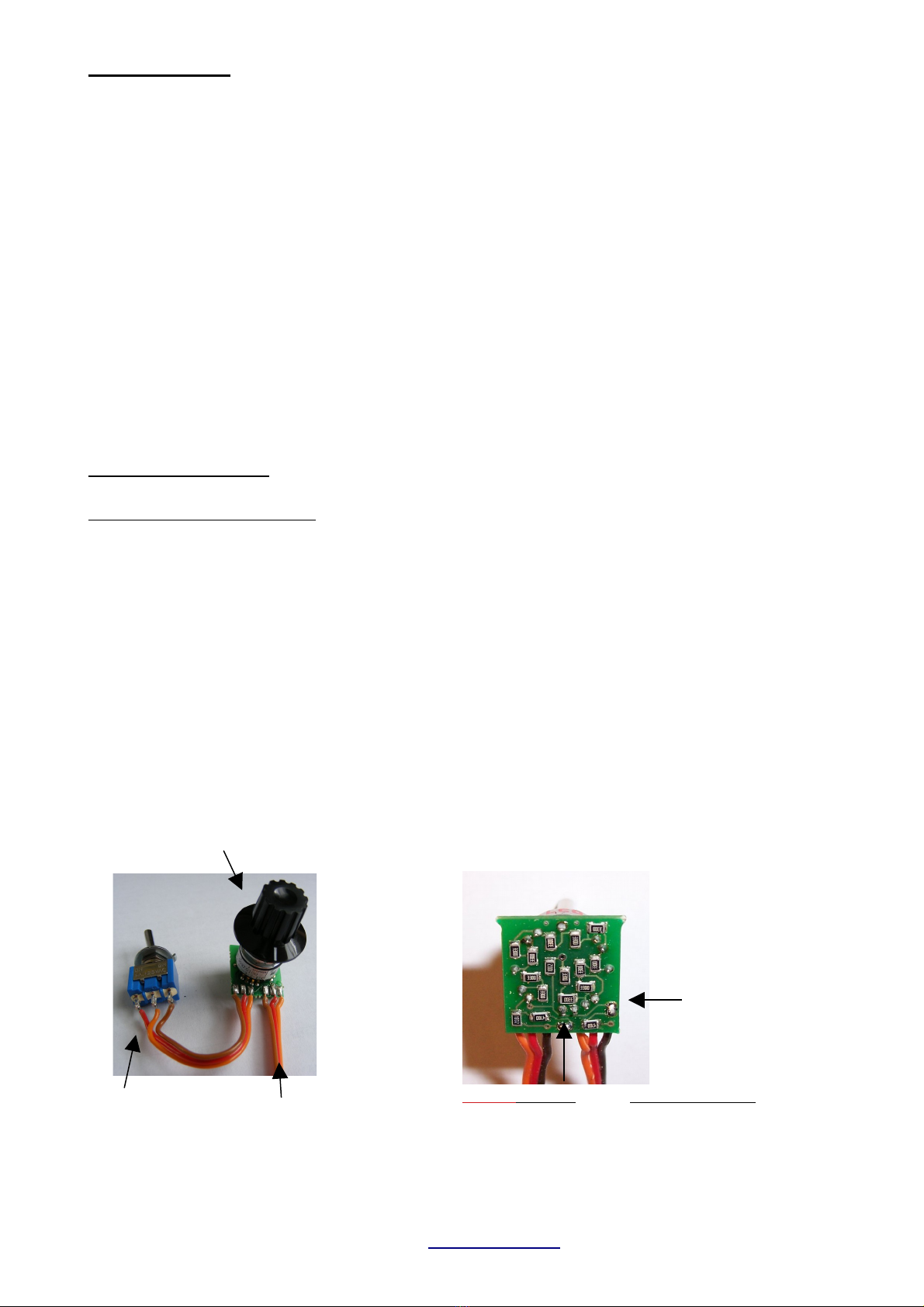
.1. Encoder (12-Key coder)
The most comfortable way of controlling the sound unit is using the so called “12-key coder”. It is a
12 osition rotary switch in combination with a ush button. The desired sound is selected by the
rotary switch and is triggered by the ush button.
The encoder is mounted in your transmitter and connected to a s are ro ortional channel.
Electrically, it is a sim le otentiometer with adjustable total resistance (see icture below).
The encoder is optional and must be ordered separately!
After installation the encoder should be tested by a common servo at the according receiver
channel. KEEP the encoder ush button ressed while moving the rotary switch through all
ositions. The attached servo must move to a new location at each rotary switch osition. The total
movement of the servo should be about the same as at a normal joystick channels set to 100%
travel.
TBS Mini V2, 11/2018 www.benedini.de Page 7 of 13
Connect to s are ro .
Channel of your TX.
trigger switch
Rotary switch for
sound selection
BOTH bridges Total resistance
o en a . 22 KOhm
closed a . 5 KOhm
The total resistance of the encoder can be
adjusted to your TX by two solder bridges at
the rear side of the encoder cb:

.1.1. Push button encoder
A sim le resistor array combined with some ush buttons can be also used to control the sound
unit in 12-key coder mode. This is only a suggestion and needs to be build by your own:
Zum Sender
S1 S2 S3 S4 S5 S6 S7 S8 S12S9 S10 S11
5k6
R12
390
R1
390
R2
390
R3
390
R4
390
R5
820
R6
390
R7
390
R8
390
R9
390
R10
390
R11
5k6
R13
5k
CW
P1
5k
CW
P2
3
1
2
ST1
You should check the o eration by a common servo. Adjust the min. and max. travel range with
the otentiometers P1 and P2 in com arison to the travel at a common joystick channel(f.e.Ch1).
The installation of ANY encoder in your transmitter is on your own risk
Proper functionality is not guaranteed in ALL transmitter brands / types
After installation the proper operation and range of the radio MUST be checked
.1.2. Teaching the sound unit for encoder control
1) Power transmitter and receiver. LED blinks fast -> normal mode
Bring all joysticks to neutral osition. Model must not move.
2) Press the LEARN button at the TBS Mini until one bee lays -> LED cont. lit.
At this moment all neutral / idle ositions are stored.
3) Move throttle stick to your desired acceleration oint (throttle stick osition where
idle sound is left and acceleration sound is started) and ush the encoder trigger
button ! -> A short sequence of acceleration is layed
4) Move throttle stick to full s eed and ush the encoder trigger button again
→ A short sequence of full s eed is layed.
5) Bring the encoder rotary switch to its first osition and ush the encoder button
→ Engine start/sto is stored to this osition
Hint: The rotary switch has no mechanical limits. You can define any osition as the
“first” one.
6) Bring the encoder rotary switch to the next osition, wait about 2s and ush the
encoder button again.
-> Reeving u the engine is stored to this osition
7) Re eat ste 6 until all 12 rotary switch ositions are stored
8) After teaching all ositions the sound unit bee s 3x and is back in normal o eration
mode.
Hint:
If you are using the resistor network shown above instead of the encoder, each rotary switch
osition is re resented by one of the ush buttons.
TBS Mini V2, 11/2018 www.benedini.de Page 8 of 13

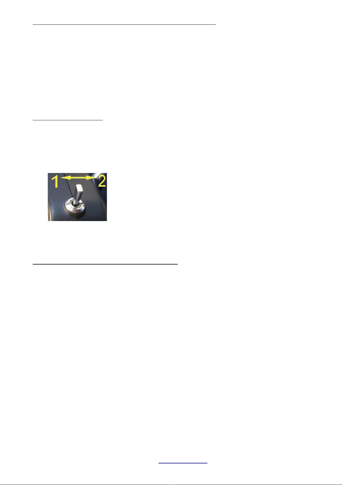
.2. Direct sound selection
If you want to have engine sound and ONE s ecial sound (f.e. MG), you can use this control mode.
A ro ortional s are channel having a 3 osition switch or a common joystick channel are
necessary for using this mode.
A attached servo must leave its center/neutral osition if the switch is ressed in one direction and
must return to its center osition when the switch is released. Pushing the switch in the o osite
direction causes the servo moving to the other side. Please com are the very left and very right
ositions of the servo with a common joystick channel. They should be about the same.
This is the first test you should do before teaching the sound unit.
.2.1. Teaching direct sound selection using Prop2 input (recommended !!!)
The 3 os switch receiver channel must be connected to Prop2 in ut of the TBS Mini. Pro 2 in ut
mode must be set to “Function ½” at the TBS Flash software. The desired sounds must be selected
too. These settings are already done if this control mode was ordered.
Teaching is very sim le and is the same as described below in “.4. Autostart” → Page 10
Hint:
The two selectable sounds are fix (as set by the TBS Flash rogram) and can not be changed during
teaching. They can be changed only by the o tional USB rogramming cable.
.2.2. Teaching the direct sound selection using Prop input
(Recommended for experienced users)
This is a alternative method for direct sound selection. It can be used if the model has two s eed
channels. In this case Pro 2 can be used for the second s eed in ut and Pro 3 for sound selection.
1. Power on transmitter and receiver. LED blinks fast -> normal mode
Bring all joysticks to neutral osition. Model must not move.
2. Press the rog. button until one bee occurs -> LED cont. on.
At this moment all neutral / idle ositions are stored.
3. Move throttle stick to your desired acceleration oint (throttle stick osition where to leave idle
and start the acceleration sound), flick the toggle switch and set it back to center.
-> A short sequence of acceleration is layed
4. Move throttle stick to full s eed osition, flick the switch again and set it back to center.
-> A short sequence of full s eed is layed.
5. Flick the switch UP and set it back to center
-> Engine start/sto is stored to this switching direction
6. If you want to skip the next sound, flick the switch again UP. A section of the next sound is
layed but NOT stored to this direction of the switch, because it is already occu ied.
7. Re eat ste 6 to skip further sounds
8. If your desired s ecial sound comes u next flick the switch DOWN and set it back to center.
9. Switch sound unit off and on.
10. Now you can select the two selected sounds directly by o erating the switch u or down.
Hint:
–The control mode for Pro 3 must be set to “12 position encoder”
–The 3- os switch receiver channel must be connected to Prop
–You may run the teaching sequence several times because you don't know at the very first run
which sound a ears next in the sound list.
–Advantage of this way of using the direct mode is, that you can choose the sounds you want to
have during teaching.
TBS Mini V2, 11/2018 www.benedini.de Page 9 of 13
. . Indirect sound selection “2-Key Coder” on Prop
This control mode allows laying ALL loaded sounds of the TBS Mini.
A s are ro ortional channel of your radio having a 3 osition switch with neutral osition or a
common joystick channel can be used.
A attached servo must leave its center/neutral osition when the switch is ressed in one direction
and must return to its center osition when the switch is released. Pushing the switch in the o osite
direction causes the servo moving to the other side.
Please com are the very left and right ositions of the servo with a common joystick channel. They
should be about the same.
This is the first test you should do before teaching the sound unit.
Operation of this mode:
The desired sound (f.e. sound #3) is SELECTED by ushing the switch/joystick 3 times from its
center osition to one direction, but it is NOT layed. The already selected sound is
TRIGGERED by ushing the switch to the other direction. The last selection can be triggered
multi le times.
1: Selection of sound / action (1-12)
2: Triggering of selected sound / action
. .1. Teaching the “2-Key Coder” control
1. Power on transmitter and receiver. LED blinks fast -> normal mode.
Bring throttle stick(s) to neutral and the 3- osition control switch to its center osition
2. Press the rogramming button -> Bee and LED ermanent on.
At this moment all neutral ositions are stored.
3. Move throttle stick to your desired acceleration oint and kee this osition.
(throttle stick osition where the engine sound leaves idle)
4. Flick the 3- osition control switch at the transmitter and set it back to center
-> A short sequence of acceleration is layed.
5. Move the throttle stick to full s eed and kee this osition
6. Flick the 3- osition control switch at the transmitter and set it back to center
-> A short sequence of full s eed is layed.
7. Sound unit returns to normal o eration mode → Green LED is blinking fast
TBS Mini V2, 11/2018 www.benedini.de Page 10 of 13

.4. Autostart
If you want to have ONLY engine sound, “Autostart” mode can be used. The engine starts
automatically at first short acceleration.
If the engine runs more than 20s idle, it shuts down automatically.
There is no extra s are channel of your radio necessary.
Hint: NO special sounds and NO switching outputs are ossible !!!!
Teaching the autostart mode:
1. Power on transmitter and receiver. LED blinks fast -> normal mode
Bring throttle stick to idle. Motor must not move.
2. Press the rogramming button until bee -> LED cont. on.
At this moment the idle osition of the throttle stick is stored.
3. Move throttle stick to your desired acceleration oint and wait for a bee
(throttle stick osition where idle sound is left and acceleration sound is started)
4. Move the throttle stick to full s eed osition and wait for three bee s.
5. Sound unit returns to normal o eration mode → Green LED is blinking fast
Hint:
After you left the last stored throttle stick position, a very short beep is played. Since then,
you have about 2 seconds to adjust the new throttle stick position to be stored next.
4. Changing a already set control mode
The control mode can be changed also manually by the learn button of the TBS Mini without the
o tional rogramming cable and the TBS Flash software.
1. KEEP the learn button of the TBS Mini ressed while owering the receiver.
2. Release the button
3. Press the learn button momentarily and wait for the “Bee -Code”
4. Re eat ressing the button until the desired control mode is signalized by the according
“Bee -Code”
5. Switch sound module off and on again
„Beep-Code“
1 x Bee -> Autostart
2 x Bee -> Indirect sound selection (2-Key coder)
3 x Bee -> 12- Key coder
Note:
This will NOT work for changes from Autostart to 2-key or 12-key coder mode, due to a missing
sound list definition.
Changes vice versa are ossible.
TBS Mini V2, 11/2018 www.benedini.de Page 11 of 13

6. Configuration of the soundunit by the optional programming cable and a
common PC
Please see the se arate manual for the configuration software called “TBS Flash”.
The manual as well as the software is available free of charge at www.benedini.de.
Note:
The sound unit must be owered from the receiver or a receiver battery while being connected to
the PC. It is NOT owered by the USB cable!
7. Technical datas
Power su ly: 3,5V – max. 6V ( owered from the receiver)
Internal am lifier: 3W at 4 Ohm and 5V su ly
Switching out uts: Negative switching, max. 12V/0,5A each
Dimensions: 55 x 28 x 10mm
Weight: about 6g
!!!! SAFETY ASPECTS !!!!
- You must do a range check of your remote control with running sound system !
- Ensure a ro er working radio under ALL conditions !
- Receiver Power supply:
If a speed controller BEC is used for owering the receiver, it is highly recommended using a
se arate servo Y-cable for connecting the receiver to the ESC and the TBS Mini (s eed channel).
In this case the receiver is owered directly and not via the two Pro 1 connectors of the TBS Mini.
Maximum current of the Pro 1 connectors are 2A, if according wires are used!
- The switching out uts of the TBS Mini MUST not be used to trigger any dangerous actions in the
model (f.e. triggering any firing mechanisms)
Disclaimer
a.) www.benedini.de rovides the equi ment solely to be used by each urchaser in accordance with the s ecific
instructions su lied with each Sound Module and that the urchaser undertakes that the Sound Module and any
associated equi ment e.g. Am lifier, S eakers, etc. will be o erated within the arameters contained therein.
b.) www.benedini.de acce ts no liability for any damage to any Sound Module if it is determined that the damage has
been caused by either non adherence to the instructions or due to any malfunction by any cause or reason whatsoever
within the model or its equi ment and thereby outside of the control of www.benedini.de.
c.) www.benedini.de su lies each Sound Module on the strict undertaking that it will be used in such a manner to
com ly with the laws of the urchaser’s country of residence.
d.) www.benedini.de has no control over the final assembly, no liability shall be assumed nor acce ted for any damage
resulting from any use by user of the final assembled roduct, the user acce ts all resulting liability.
Technical changes reserved Not suitable for children under 14 years
Benedini Modellbauelektronik
Müllergasse 15, 52159 Roetgen, Germany
Web: www.benedini.de
Mail: [email protected]
TBS Mini V2, 11/2018 www.benedini.de Page 12 of 13

Other manuals for TBS Mini V2
1
Table of contents
Other Benedini Recording Equipment manuals


Popular Recording Equipment manuals by other brands


Sony
Sony XDCAM PDW-U1 brochure

Tascam
Tascam CD-RW901 Technical documentation

Behringer
Behringer PRO MIXER DJX750 quick start guide

Doug Fleenor Design
Doug Fleenor Design PRE10ETHER-A owner's manual

Marshall Amplification
Marshall Amplification JVM2 Series user manual

OTC DAIHEN EUROPE
OTC DAIHEN EUROPE Almega AX Series instruction manual