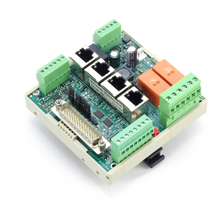
Benezan Electronics Beamicon2 IoExt1 User manual

Benezan Electronics
Hard- and software development
IoExt installation guide
Nicolas Benezan, Stauffenbergstr. 26, 72108 Rottenburg
Phone: +49 (0) 7457/946365 0 benezan-electronics.de
Page
Io-Ext1-Installation.docx22.09.2020
Beamicon2 IoExt1
Input/output extension for
CNC control with Ethernet interface
Installation manual
Version 1
Brief product description
The IO Expansion provides additional digital inputs and outputs for the Beamicon2 CNC control. This means
that the number of available inputs and outputs is not limited to the limited number on the NetBOB or the
CncPod, but can be expanded practically at will.
The module has eight outputs and eight inputs with 24V level. Unused outputs can also be used as inputs, so
that up to 16 inputs are available alternatively. A normal network connection with RJ45 cable is used for data
transfer from the PC. A network switch is required to connect several modules to one PC. All signals are
galvanically isolated from the PC. All outputs and inputs are equipped with filters and protected against short-
circuit and polarity reversal, so that a maximum of interference immunity is achieved.

Benezan Electronics
Hard- and software development
IoExt installation guide
Nicolas Benezan, Stauffenbergstr. 26, 72108 Rottenburg
Phone: +49 (0) 7457/946365 0 benezan-electronics.de
Page
Io-Ext1-Installation.docx22.09.2020
Safety Instructions
The interface board may only be installed and put into operation by qualified personnel.
Please read the operating instructions carefully and follow all instructions exactly. Improper
installation or operation of the device can cause damage to the electronics or the machine and
can result in dangers to the health of the operating personnel.
Depending on the hazard potential of the machine, additional safety measures may be
required, such as door interlocks and standstill monitoring. As a rule, such safety functions
must be implemented purely electromechanically with external circuits (not included in the
scope of delivery) and must not depend solely on software and PC hardware. The system manufacturer, who
assembles the interface board and other components to form the overall system, and the system operator are
responsible for compliance with the legal regulations.
Connections
(All pins of the terminals are numbered
from left to right or from top to bottom)
Status LEDs
LED No.
Description
-
Outputs (X9 to X12, top)
-
Inputs (X1 to X8, bottom)
Network traffic
Network Carrier (connected)
Outputs (terminals above)
Pin No.
Assignment
1
0V Ground
2
Signal output (max. 250mA)
3
0V Ground
4
Signal output (max. 250mA)
Supply
voltage(terminal X13 right above)
Pin No.
Assignment
1
+24V output (max. 100mA)
2
Signal input
3
0V signal ground
Inputs (terminals below)
Functional description
No.
Description
1
Signal ground
2
+24V input (10..30V)
C
T
8
1
8
1
1
C
1
2
3
4
5
6
7
8
2
3
4
5
6
7
T
8

Benezan Electronics
Hard- and software development
IoExt installation guide
Nicolas Benezan, Stauffenbergstr. 26, 72108 Rottenburg
Phone: +49 (0) 7457/946365 0 benezan-electronics.de
Page
Io-Ext1-Installation.docx22.09.2020
PC / network connection
The data transfer from the PC software to the CncPod is done via an Ethernet network connection (IEEE802.3
10BASE-T). The connection can be made with standard patch cables to the RJ45 socket ST1.
In contrast to similar products from competitors (e.g. Smoothstepper or Eding-CNC) no exclusive interface
has to be reserved on the PC, but the infrastructure of an existing network with switches can be used. There is
also no need to change IP addresses or otherwise interfere with the Windows Control Panel. The Beamicon2
software automatically detects all modules, even if it is connected "somewhere" in the network. Several modules
can be connected to a PC at the same time and can also be used simultaneously. To ensure reliable operation,
however, the following rules must be observed:
All modules must either be connected to the first switch after the PC, or a further switch may be added
if only devices of the machine are connected to the second switch, e.g. within the control cabinet of the
machine. All devices not involved in machine control (Internet router, printer, NAS, etc.) must be
connected to the first switch or to additional switches behind the first.
The transmission speed between the PC and the first switch must be higher than the maximum data rate
of any existing Internet routers (DSL modem etc.). For home networks with few PCs 100MBit is
recommended, for larger networks Gigabit-Ethernet.
Since no TCP/IP is used but a separate protocol, this cannot be forwarded by routers, external firewalls,
proxies, etc. Therefore only so-called "unmanaged switches" may be used between the control PC and
the CNC pod.
Switches must support Fast Forward and Store-and-Forward (virtually all modern switches meet this
criterion)
Hubs are also allowed for test purposes (listening with diagnostic tools on taps), but are not
recommended.
The data traffic of the machine controller must not be routed via slow (DSL modem) or unreliable
(wireless) connections (WLAN). All wireless interfaces are therefore intentionally hidden.
The network interface is galvanically isolated from the PC. Power-over-Ethernet (PoE) is not supported.
Power supply
The expansion module can be supplied with an operating voltage of 10 to 30V DC. The input is protected against
accidental reverse polarity. It is recommended to use a switching power supply with 24V, as most industrial
contactors, pneumatic valves and sensors are designed for this and can therefore be connected directly.
Connection of actuators
A total of 16 terminals (4 pluggable contact blocks with 4 connections each) are provided at the top of the
module for the connection of consumers. The connections with odd numbers 1, 3, 5 etc. are permanently
connected to ground. The actual outputs are the connections with even number 2, 4, 6 etc. The outputs are of the
PNP type, i.e. an activated output is connected to the supply voltage (24V), a deactivated one is high-impedance.
The outputs are protected against overvoltage by switching inductive loads and against short circuit. The
corresponding LED lights up when more than about 6V are applied to the output, i.e. when the output is either
switched on or a voltage is applied externally.
Connection of sensors
Each input has its own 3-pin terminal, where the supply voltage, the signal input and a ground connection is
available. This also allows a direct connection of inductive proximity switches without additional distribution
terminals. The inputs are intended for mechanical switches (normally closed or normally open) or for PNP type
sensors (switching to +). The corresponding LED lights up when more than about 6V are applied to the input.
Mechanical switches are connected with two wires to pin 1 (top) and pin 2 (middle). Inductive switches or
other electronic sensors are connected with three wires (brown=1, black=2, blue=3). If NPN types are to be used
(not recommended), an additional pull-down resistor of approx. 2.2kΩ must be connected between pins 1 and 2.
If the eight available inputs are not sufficient and not all outputs are used, outputs can also be used as inputs.
Thus, a total of up to 16 inputs are available. Since there are only two pins per input/output on the output
terminals, the supply voltage must be connected to a distribution terminal or directly to the power supply unit in
this case.

Benezan Electronics
Hard- and software development
IoExt installation guide
Nicolas Benezan, Stauffenbergstr. 26, 72108 Rottenburg
Phone: +49 (0) 7457/946365 0 benezan-electronics.de
Page
Io-Ext1-Installation.docx22.09.2020
Configuration
The assignment of the inputs and outputs is done in the Beamicon2 software. The installation and operation of
the software as well as the adjustment of the machine parameters is described in detail in the Beamicon2
software manuals. Therefore, only the special features of the expansion module will be discussed here.
After the first start, the module must first be connected. Open the hardware dialog by selecting this in the
menu under "Configuration -> Hardware". If several identical modules are connected, you may assign the
desired module with "Identify". In this case you
should remember the number of the module (8-digit
hexadecimal number, usually starting with "A3"),
because otherwise confusion could occur later when
assigning the individual inputs and outputs. Finally,
select the module and then click on "connect" and
"save".
To assign the signals, switch to the configuration
dialog (Menu -> Configuration -> Machine), and then
to the "Inputs/Outputs" page. You can now assign
existing signals (e.g. limit switches), or define new
ones (with "Add"), e.g. for your own macros.
The signals of the expansion module can be used
for (almost) any purpose, e.g
Relays or contactors for switching loads,
Pneumatic or hydraulic valves
Limit value/limit switches at the ends of the travel range of positioning axes,
"End position reached" switch on pneumatic cylinders
other sensors
However, there are the following restrictions:
The emergency stop input is assigned to a fixed input on the primary axis controller module (NetBob,
CncPod or TripleBeast)
Reference switches and tool length sensors, which have to achieve high precision in connection with
axis movements, cannot be placed on expansion modules because the propagation delay via the network
would result in a position deviation. These must be connected directly to the primary module.
Some outputs with special functions (PWM or analog output) can also only be assigned to certain pins
on the primary module.

Benezan Electronics
Hard- and software development
IoExt installation guide
Nicolas Benezan, Stauffenbergstr. 26, 72108 Rottenburg
Phone: +49 (0) 7457/946365 0 benezan-electronics.de
Page
Io-Ext1-Installation.docx22.09.2020
Technical data
Absolute limit values
The following parameters must not be exceeded under any circumstances to prevent damage to the device:
Parameters
min.
max.
Unit
Operating voltage
-40
+40
V
Storage temperature
-40
+70
°C
Operating temperature
0
+70
°C
Voltage at digital inputs
-40
+40
V
Voltage at digital outputs
-0.5
+40
V
Electrical connection values:
Parameters
min.
max.
Unit
Operating voltage (Vcc, nominal 24V)
+10
+30
V
Power consumption (without external consumers)
0.1
2
W
Ambient temperature
0
+50
°C
Level for logical 0 at inputs
-0.5
+5
V
Level for logical 1 at inputs
8.0
30
V
Current consumption at inputs at 24V
3
5
mA
Level for logical 0 at outputs
0
0.5
V
Level for logic 1 at outputs
Vcc-2
Vcc
V
Load current at outputs
0
250
mA
Switch-off energy with inductive load
0
3
mJ
Dimensions:
Description
Width
Length
Height
Unit
Dimension of the board without connector
56
62
8
mm
Dimensions with plug
56
82
22
mm
Other manuals for Beamicon2 IoExt1
1
Table of contents
Other Benezan Electronics Computer Hardware manuals
Popular Computer Hardware manuals by other brands

Sun Microsystems
Sun Microsystems 2060 Hardware Engineering Manual

Radica Games
Radica Games DAVID-II 716 Operating and maintenance instruction manual

MSA
MSA ProtoCessor FPC-ED2 operating manual

Watercool
Watercool HEATKILLER GPU-X3 GTX 560 Assembly instructions

Creative
Creative EF0960 Safety & Regulatory Guide
Alphacool
Alphacool Cool Answer manual
