Benezan Electronics NetBob2 User manual

Benezan Electronics
Hard- and software development
NetBob2 Installation ManualEthernet CNC
Interface
Nicolas Benezan, Stauffenbergstr. 26, 72108 Rottenburg
Phone: +49 (0) 7457/946365 0 benezan-electronics.de
Page
NetBob2-Installation_Englisch (Vereinigte
Staaten).docx 23.09.2020
Beamicon2 Breakout Board
Interface board for
CNC control up to
6 axes via Ethernet
Installation manual
Version 1
Brief product description
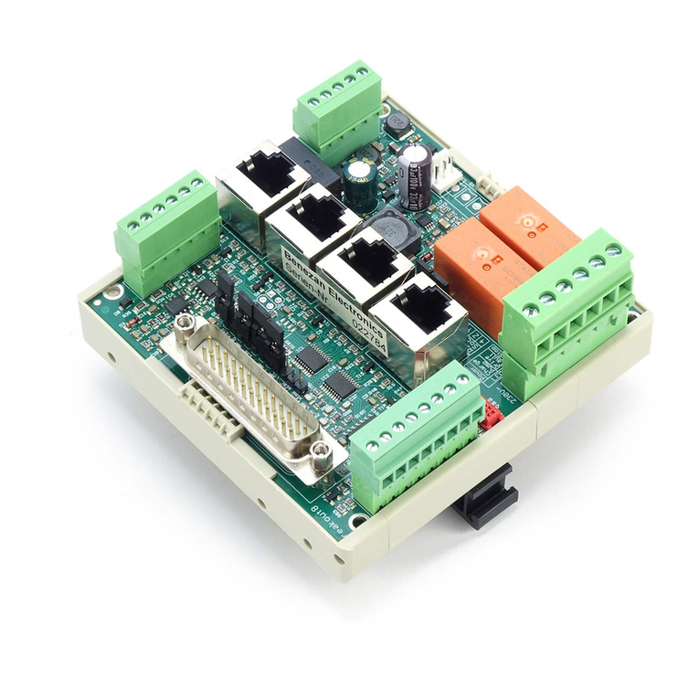
The interface board allows the operation of up to six stepper motor or servo output stages with the Beamicon2
CNC software. A normal network connection with RJ45 cable is used for data transfer from the PC. No LPT port
is required, and the well-known limitations of step frequency and timing problems are a thing of the past. The
board can be adjusted to many different configurations. Depending on the selected configuration, additional
functions such as control of a frequency converter or speed controller, reference switches, up to 9 outputs (24V)
and up to 16 inputs (24V) are available.
All signals are galvanically isolated from the PC, so that a maximum of noise immunity is achieved. All
machine-side signals are designed for 24V level, ensuring robustness and compatibility with industrial sensors.
Ready-made connection cables for BEAST stepper motor power amplifiers, UHU-DC servo controllers and
brushless servo systems (SpeedCube and Sanyo-Denki R-series) are available (not included), so that quick and
error-free wiring is possible.

Benezan Electronics
Hard- and software development
NetBob2 Installation ManualEthernet CNC
Interface
Nicolas Benezan, Stauffenbergstr. 26, 72108 Rottenburg
Phone: +49 (0) 7457/946365 0 benezan-electronics.de
Page
NetBob2-Installation_Englisch (Vereinigte
Staaten).docx 23.09.2020
Safety Instructions
The interface board may only be installed and put into operation by qualified personnel.
Please read the operating instructions carefully and follow all instructions exactly. Improper
installation or operation of the device can cause damage to the electronics or the machine and
can result in dangers to the health of the operating personnel.
Depending on the hazard potential of the machine, additional safety measures may be
required, such as door interlocks and standstill monitoring. As a rule, such safety functions
must be implemented purely electromechanically with external circuits (not included in the
scope of delivery) and must not depend solely on software and PC hardware. The system manufacturer, who
assembles the interface board and other components to form the overall system, and the system operator are
responsible for compliance with the legal regulations.
Connections
The connections of all terminals are numbered from left to right. The contacts of the RJ45 jacks are also
numbered from left to right.

Benezan Electronics
Hard- and software development
NetBob2 Installation ManualEthernet CNC
Interface
Nicolas Benezan, Stauffenbergstr. 26, 72108 Rottenburg
Phone: +49 (0) 7457/946365 0 benezan-electronics.de
Page
NetBob2-Installation_Englisch (Vereinigte
Staaten).docx 23.09.2020
Additional functions
(6-pin terminal X2, top left)
No.
Description
1
Ground 0V for output 9
2
Output 9 (holding brake)
3
Analog output ground 0V
4
Analog output 0..10V
5
Emergency stop switch Input
6
Emergency stop switch +24V
output
Switch inputs
(8-pin terminals X3-X6, bottom)
No.
Description X3
1
Reference switch X voltage output (+24V)
2
Reference switch X Signal input
3
Reference switch Y Voltage output (+24V)
4
Reference switch Y Signal input
5
Reference switch Z Voltage output (+24V)
6
Reference switch Z Signal input
7
Reference switch 4th axis voltage output (+24V)
8
Reference switch 4th axis Signal input
No.
Description X4
1
Reference switch 5th axis voltage output (+24V)
2
Reference switch 5. axis Signal input
3
Reference switch 6th axis voltage output (+24V)
4
Reference switch 6. axis Signal input
5
Input 1 voltage output (+24V)
6
Input 1 Signal input
7
Input 2 Voltage output (+24V)
8
Input 2 Signal input
No.
Description X5
1
Input 3 Voltage output (+24V)
2
Input 3 Signal input
3
Input 4 Voltage output (+24V)
4
Input 4 Signal input
5
Input 5 Voltage output (+24V)
6
Input 5 Signal input
7
Input 6 Voltage output (+24V)
8
Input 6 Signal input
No.
Description X6
1
Input 7 Voltage output (+24V)
2
Input 7 Signal input
3
Input 8 Voltage output (+24V)
4
Input 8 Signal input
5
Input 9 Voltage output (+24V)
6
Input 9 Signal input
7
Input 10 Voltage output (+24V)
8
Input 10 Signal input

Benezan Electronics
Hard- and software development
NetBob2 Installation ManualEthernet CNC
Interface
Nicolas Benezan, Stauffenbergstr. 26, 72108 Rottenburg
Phone: +49 (0) 7457/946365 0 benezan-electronics.de
Page
NetBob2-Installation_Englisch (Vereinigte
Staaten).docx 23.09.2020
Power supply
(5-pole terminal X1, top right)
No.
Description
1
5V output (max. 0.3A)
2
Ground 0V
3
12V output (max. 0.3A)
4
Ground 0V
5
24V input (15..36V)
Outputs
(4-pin terminals X8-X11, top)
No.
Description X8
1
Ground 0V for output 1
2
Output 1
3
Ground 0V for output 2
4
Output 2
No.
Description X9
1
Ground 0V for output 3
2
Output 3
3
Ground 0V for output 4
4
Output 4
No.
Description X10
1
Ground 0V for output 5
2
Output 5
3
Ground 0V for output 6
4
Output 6
No.
Description X11
1
Ground 0V for output 7
2
Output 7
3
Ground 0V for output 8
4
Output 8
Modbus
(3-pole terminal X7, top)
No.
Description
1
Signal ground
2
Data -
3
Data +
Status LEDs
No.
Description
Power
Ready
Drive fault
E-Stop
Output 1
Output 2
Network Carrier (connected)
Network traffic
Power stage outputs (6 x RJ45, center)
No.
Description
1
+ Current reduction / servo enable
2
- Current reduction / servo enable
3
- Step / Clock
4
+ Direction
5
- Direction
6
+ step / beat
7
+ Status (Ready / Alarm)
8
- Status
Other connections:
Network / PC (ST9 bottom left)
Fan (ST7, top right)
External LEDs (ST8, left)
8
7
6
5
4
3
2
1

Benezan Electronics
Hard- and software development
NetBob2 Installation ManualEthernet CNC
Interface
Nicolas Benezan, Stauffenbergstr. 26, 72108 Rottenburg
Phone: +49 (0) 7457/946365 0 benezan-electronics.de
Page
NetBob2-Installation_Englisch (Vereinigte
Staaten).docx 23.09.2020
Functional description
In contrast to conventional breakout boards with LPT interface, which only pass on the signals from the PC and,
if necessary, adjust or amplify the signal levels, the Beamicon2 interface board has a powerful 32-bit processor,
which can generate step and direction signals in real time independently of the PC. The PC only sends
coordinates at regular intervals via a network interface (Ethernet IEEE802, 10MBit/s). All hardware-related
operations run on the interface board, so that the PC is relieved of time-critical tasks and is only needed for the
user interface.
Much higher step rates are possible than with LPT port-based solutions, and the timing is more precise and
reliable. Compromises in the selection of the resolution in connection with the maximum possible speed are
therefore no longer necessary. Servo drives can also be operated with high resolution and speed. Step losses due
to short "dropouts" of the PC (violations of real-time conditions by competing processes) are excluded.
Even settings for pulse duration and distance, which are often difficult for the user to understand, can be
completely omitted. The breakout board always generates the step signals with a duty cycle of 50%. Changes of
direction always occur in the middle of the pauses between clock pulses. This ensures that always the maximum
pulse duration matching the frequency is output. Violations of the setup and hold time by simultaneous change
of step and direction signal state are avoided.
Compared to the NetBob1, 6 instead of only 4 axes and considerably more inputs and outputs are available.
The step/direction signals are differential (RS422), so that the connection of servocontrollers requiring
differential signals is simplified. All enable and status signals are available separately for each axis, so that even
mixed axis drives (stepper motors and servos) are no problem, and diagnosis in the event of an error is easier.
PC / network connection
The data transfer from the PC software to the breakout board is done via an Ethernet network connection
(IEEE802.3 10BASE-T). The connection can be made with standard patch cables to the RJ45 socket ST9. Please
note that the other four RJ45 sockets ST1 to ST6 (without LEDs) are not network connections but are intended
for step/direction signals.
In contrast to similar products from competitors (e.g. Smoothstepper or Eding-CNC) no exclusive interface
has to be reserved on the PC, but the infrastructure of an existing network with switches can be used. There is
also no need to change IP addresses or otherwise interfere with the Windows Control Panel. The Beamicon2
software automatically detects the breakout board, even if it is connected "somewhere" in the network. To ensure
reliable operation, however, the following rules must be observed:
The breakout board must be connected either directly to the PC or to the first switch after the PC. A
further switch may only be added if only devices of the machine are connected to the second switch,
e.g. within the control cabinet of the machine. All devices not involved in machine control (Internet
router, printer, NAS, etc.) must be connected to the first switch or to additional switches behind the
first.
The transmission speed between the PC and the first switch must be higher than the maximum data rate
of any existing Internet routers (DSL modem etc.). For home networks with few PCs 100MBit is
recommended, for larger networks Gigabit-Ethernet.
Since no TCP/IP is used but a separate protocol, this cannot be forwarded by routers, external firewalls,
proxies, etc. Therefore only so-called "unmanaged switches" may be used between the control PC and
the CNC pod.
Switches must support Fast Forward and Store-and-Forward (virtually all modern switches meet this
criterion)
Hubs are also allowed for test purposes (listening with diagnostic tools on taps), but are not
recommended.
The data traffic of the machine controller must not be routed via slow (DSL modem) or unreliable
(wireless) connections (WLAN). All wireless interfaces are therefore intentionally hidden.
If the board is connected directly to the PC and the PC interface does not support automatic crossover, a
crossover cable must be used (usually marked with a red plug or "X"). The network interface is galvanically
isolated from the PC. Power-over-Ethernet (PoE) is not supported.

Benezan Electronics
Hard- and software development
NetBob2 Installation ManualEthernet CNC
Interface
Nicolas Benezan, Stauffenbergstr. 26, 72108 Rottenburg
Phone: +49 (0) 7457/946365 0 benezan-electronics.de
Page
NetBob2-Installation_Englisch (Vereinigte
Staaten).docx 23.09.2020
Power supply
The breakout board can be supplied with an operating voltage of 15 to 36V DC. It is recommended to use a
power supply with 24V and 1A to 10A current carrying capacity.
For fans, external sensors or additional circuits the board provides regulated 5V and 12V outputs (terminal
X1). A 3-pole plug-in socket is provided for standard PC fans with 12V (ST7). The outputs are short-circuit
proof. However, since the same voltage regulators are also used for the internal supply, malfunctions can occur
in the event of a short circuit. In case of overload or undervoltage at the 12V connection the E-Stop LED (red)
lights up.
Power stage signals
The outputs of the step/direction signals are equipped with RJ45 sockets so that BEAST stepper motor power
amplifiers and UHU or Speedcube servo controllers can be connected with standard Ethernet patch cables. To
avoid confusion with the PC network cables, it is recommended to use different cable colours, e.g. grey for the
network data lines, yellow for the step/direction signals.
All signals (step, direction, enable or current reduction output and status input) are differential (RS422 with
26C31 drivers and 26C32 receivers). This leads to better interference resistance and simplifies the connection of
industrial servo controllers that require differential signals (e.g. SanyoDenki, Hitachi, Panasonic, etc.).
The enable outputs and status inputs of all six axes can be controlled separately and can be assigned
individually via the software. This also allows mixed operation of different drive types. In the event of a
problem, it is possible to determine which of the axes is reporting an alarm.
Connection of BEAST output stages
The following options are available when using BEAST power
amplifiers:
1. The current reduction signal is applied to the enable signal (pin
1).
2. The automatic current reduction of the output stages is used
(activate DIP switch 3 on the BEAST)
3. No current reduction is used (Enable not used, DIP3 on BEAST
off)
Connection of other stepper motor output stages
(leadshine etc.)
For the connection of most leadshine and similar power amplifiers there are suitable adapters to connect the
signals of the RJ45 connector to the terminals of the power amplifier (see picture). If you do not have an adapter,
you can also simply cut the plug of the second cable end and connect the wires individually to the terminals.
Attention - the wire colours are only valid for patch cables according to T568B standard (no crossover!)
Please note that the enable input of the power stage is inverted, i.e. when voltage is applied to ENA+/ENA- the
power stage is switched off instead of on. If the power stage is to be switched off in the event of an emergency
stop, the "Servo Enable Inverted" signal (#O17) must be assigned to the enable pin (Enable1..Enable6). If the
power stage is to remain active during an emergency stop (recommended, shorter braking distance), the enable
RJ45
Pin No.
Wire colour
Output stage Signal
1
white-orange
ENA+
2
orange
ENA-
3
white-green
PUL-
4
blue
DIR+
5
white-blue
DIR-
6
green
PUL+
7
white-brown
]Bridge
8
brown

Benezan Electronics
Hard- and software development
NetBob2 Installation ManualEthernet CNC
Interface
Nicolas Benezan, Stauffenbergstr. 26, 72108 Rottenburg
Phone: +49 (0) 7457/946365 0 benezan-electronics.de
Page
NetBob2-Installation_Englisch (Vereinigte
Staaten).docx 23.09.2020
pin must not be assigned. Alternatively, the signals ENA+/- can be omitted, i.e. not connected to the terminal of
the power amplifier.
Attention, the ENA input must not be used for security relevant functions. Safety against unexpected
movement is only achieved with this type of output stage if the supply voltage is completely switched off with a
safety relay.
SpeedCube Serocontroller
The servo controllers from Benezan Electronics are connected with normal patch cables like BEAST power
amplifiers, only that instead of the current reduction signal the servo enable signal is assigned.
Connection of hybrid servos, JMC servos etc.
Warning - the operation of low-cost servo drives from the Far East (JMC and similar) represents a safety risk
and is therefore expressly NOT recommended, even though connection to the breakout board is technically
possible and positioning operation works perfectly.
As far as we know, it is not possible with these drives to comply with the safety directive for CNC machine
tools applicable in Europe and at the same time still be able to work sensibly. Switching off the drives via the
Enable input is not sufficiently safe for personal protection. Switching off the motor supply voltage leads to loss
of position and would require a new reference run after each emergency stop or opening of the safety doors,
which is therefore usually not done.
When routing the step/direction signals and the motor supply voltage in the same cable, care must also be
taken to ensure that sufficient insulation is provided and that the connectors and terminals are protected against
penetration of chips, cooling water, etc. A short circuit between step/direction signals (5V) and higher voltages
(24V, 48V and higher) will immediately destroy the board. The motors must be grounded reliably! Earthing
via the fixing screws is generally not sufficient, as the bearings of the moving parts (portal, Z-axis) can slide on
an oil/grease film when moving. The power supply potential can shift via the parasitic capacitances of the motor
windings compared to PE, which can lead to dangerous voltage differences. We therefore strongly recommend
that you also connect the negative pole of the motor power supply unit to PE.
Attention - the wire colours are only valid for patch cables according to T568B standard (no crossover!)
RJ45
Pin No.
Wire colour
Output stage Signal
1
white-orange
ENA+
2
orange
ENA-
3
white-green
PUL-
4
blue
DIR+
5
white-blue
DIR-
6
green
PUL+ and ALM+
7
white-brown
ALM and resistance
8
brown
Resistance (see picture on the right)
Please note that the signals ENA+/- and ALM+/- have negative logic when delivered, i.e. voltage at ENA+/-
turns the controller off instead of on. This can lead to dangerous conditions, because an interruption will result in
an unintentional start of the drive. In addition, a cable break or a power failure at the motor cannot be detected
with the ALM signal, because the rest end (no voltage) means OK and voltage at ALM means error and not vice
versa.
Operation in this configuration is not permitted if unintentional starting of the drive could pose a danger to the
operator with the risk of serious injury, which is practically always the case with machine tools. Use at your
own risk - Benezan Electronics declines all responsibility. Some drives support setting the polarity of the ENA
and ALM signals using PC software. Nevertheless, their use is not safe enough for personal protection.

Benezan Electronics
Hard- and software development
NetBob2 Installation ManualEthernet CNC
Interface
Nicolas Benezan, Stauffenbergstr. 26, 72108 Rottenburg
Phone: +49 (0) 7457/946365 0 benezan-electronics.de
Page
NetBob2-Installation_Englisch (Vereinigte
Staaten).docx 23.09.2020
Connection of industrial servos
The breakout board can also be operated together with industrial servos which support a position control mode
with step/direction signals, e.g. the Speedcube controllers from Benezan Electronics or the RS1A series from
SanyoDenki. These controllers have a separate connection for motor operating voltage and internal supply or
have inputs for safe stop. This allows safe stopping of the drives in case of emergency stop or open doors. With
additional effort, a set-up mode (travel at reduced speed with open door) can also be implemented. Adapter
cables, circuit diagrams and support services for the adjustment are available on request and against payment.
Outputs
The breakout board has a total of nine outputs with 24V level (positive logic, i.e. PNP type). The outputs 1-8 can
be loaded with max. 250mA each, which is sufficient for most relays, contactors and solenoid valves. Output no.
9 can be loaded with up to 3A. If an electromagnetic holding brake is required for the Z-axis, it is recommended
to connect it to output 9.
All outputs are short-circuit proof and have protection against overvoltage peaks when switching inductive
loads. If higher voltages or higher currents are to be switched, external relays or contactors must be connected.
Switch inputs
There are a total of 16 digital inputs with 24V level (positive logic, i.e. PNP type). The first 6 are intended for
the reference switches of the 6 axes, but can also be used for other purposes.
Mechanical switches or inductive proximity switches of the PNP type can be used. The sensors should be
connected as follows: brown (+24V) to terminal 1, 3, 5 or 7, blue to the ground connection of the power supply
unit, black (signal) to terminal 2, 4, 6 or 8 The sum of the supply currents of the sensors at X3 and X4 is limited
to 150mA, those of the sensors at X5 and X6 also to 150mA. If the current consumption of the sensors is higher
(i.e. all together require more than 300mA), they must be supplied externally via the power supply unit. (This
protects the board from damage in case of short circuit)
The inputs are high-active, i.e. the signal is logic 1 when the connected switch is closed, or when a voltage
>8V is present at the input. The signal is logic 0 when the input is de-energized or the switch is open. If required,
all input signals can be inverted in the software.
The switch inputs have a Schmitt trigger function and are interference suppressed with a low-pass filter, so
that there is usually no need to fear interference even with unshielded cables. The inputs are overvoltage tolerant
up to +60V. Please note that the switch inputs are not suitable for fast signals (>1kHz) with 5V level, for
example TTL encoder signals.
Emergency stop
The breakout board has several independent functions that are used to stop the machine in case of problems:
1. An emergency stop button (mushroom/panic button) must be connected to terminals X2.5 and X2.6. If
the contact is opened, the digital outputs and the analog output are switched off. A push-button
emergency stop is indicated by the right LED (red, LED4). Additionally, an emergency stop is reported
to the PC
2. If the status output of one or more output stages reports an error or if the line of the step/direction signal
is interrupted, an error signal (drive fault) is sent to the PC. The output stage error is indicated by the
second LED from the right (red, LED3).
3. In case of missing or insufficient supply voltage, an emergency stop signal is sent to the PC, so that the
software does not continue to run uncontrolled.
4. Relay outputs and step signals are only enabled if there is a valid connection with the PC software and
the software regularly sends ready messages. If the connection is interrupted, all outputs are deactivated
after a few seconds for safety reasons.
Speed control (analog output)
In order to be able to specify the speed for a frequency converter, the breakout board has an analog output. A
voltage 0..10V proportional to the duty cycle of the PWM signal is output. Here 0% (low) corresponds to a

Benezan Electronics
Hard- and software development
NetBob2 Installation ManualEthernet CNC
Interface
Nicolas Benezan, Stauffenbergstr. 26, 72108 Rottenburg
Phone: +49 (0) 7457/946365 0 benezan-electronics.de
Page
NetBob2-Installation_Englisch (Vereinigte
Staaten).docx 23.09.2020
voltage of 0V, 10% corresponds to 1V, 20% corresponds to 2V etc. up to 100% and 10V. The frequency of the
PWM signal should be at least 1kHz, which is automatically the case with the sptandard setting (5kHz).
The analog output is not galvanically isolated, but referred to the power supply ground. However, this is not a
problem with all modern frequency inverters because they have an isolated speed input. Care should be taken
with old thyristor controllers whose speed input is partially connected to the mains voltage. These must not be
used. If in doubt, please refer to the data sheet of the frequency inverter or speed controller.
Please note that a frequency inverter should not be controlled exclusively with the analog signal. It is essential
that you also connect the start/stop input of the inverter to one of the digital outputs. Otherwise it is possible that
the motor does not stop completely at 0V, or that it starts unexpectedly in case of malfunctions.
Holding brake
When using ball screws, smooth-running servomotors or very heavy Z-axes, an electromechanical holding brake
must be provided to prevent the vertical axis from moving down by itself when the drive is switched off. Such
brakes are usually operated with 24V. They are blocked when no voltage is applied and open when the voltage is
switched on.
Output no. 9 has a higher current carrying capacity and is recommended for such a holding brake. If no brake
is required, the output can also be used for other purposes, e.g. as a start/stop signal for a frequency inverter. This
has the advantage that the signal is applied to the same terminal (X2).
The output has an integrated free-wheeling diode and is suitable for switching inductive loads. The output
voltage is always equal to the power supply voltage at terminal X1.5, i.e. for a 24V brake the board must then be
supplied with a 24V power supply. If the brake is to be operated pneumatically, hydraulically or with a voltage
other than the power supply voltage, an external contactor or solenoid valve is required.
External LEDs
On the left edge there is a socket (ST8) to which external status LEDs can be connected via a ribbon cable. This
is useful if the breakout board is installed in a housing where the internal LEDs are not easily visible or
accessible. A small circuit board with six LEDs and ribbon cable is available ready to use from Benezan
Electronics. The assignment of the LEDs is as follows:
No.
Description
Power
Ready
Drive fault
E-Stop
Relay 1
Relay 2
Configuration
All inputs and outputs are assigned in the Beamicon2 software. No jumpers or switches are required for
configuration.
Attention: For an unrestricted operation of the breakout board at least software version V1.72 is required.
You can find this or a newer version on the download page of Benezan Electronics (benezan-
electronics.de/downloads) under "Beamicon2 trial version with latest features".
Software settings
The installation and operation of the software as well as the adjustment of the machine parameters is described in
detail in the Beamicon2 software manuals. Therefore, only the special features of the breakout board will be
discussed here. The easiest way to configure the software is to select the default parameter set
"Default_NetBob2" the first time you start the software. Then you do not have to make all settings again, but
6
5
4
3
2
1

Benezan Electronics
Hard- and software development
NetBob2 Installation ManualEthernet CNC
Interface
Nicolas Benezan, Stauffenbergstr. 26, 72108 Rottenburg
Phone: +49 (0) 7457/946365 0 benezan-electronics.de
Page
NetBob2-Installation_Englisch (Vereinigte
Staaten).docx 23.09.2020
only enter the deviations from the standard values. You can also load the default values later by selecting "File -
> Import settings" from the menu and clicking "Default parameters".
After the first start, the breakout board must first be connected. If the hardware dialog does not open
automatically, you can do this in the menu under "Configuration -> Hardware". Select the module and then click
on "connect" and "save".
The step and direction signals for a maximum of 6 axes are automatically assigned to the RJ45 sockets. No
settings need to be made for this. In particular, there is no need to set a pulse time, as the step signal always has a
50% duty cycle. The direction of movement can be reversed in the machine parameters (Menu -> Configuration
-> Machine) on the "Axis Parameters" page with the "Inverted direction" button.
For the assignment of the signals switch to the page "Inputs/Outputs". The following input signals are
available and can be assigned to the logical signals (left table in the software):
Pin Name
Signal Description
Emergency stop
Emergency stop (triggered by mushroom button terminal X2.6, undervoltage
or connection error)
Reference 1
Reference switch no. 1 (terminal X3.2)
Reference 2
Reference switch no. 2 (terminal X3.4)
Reference 3
Reference switch no. 3 (terminal X3.6)
Reference 4
Reference switch no. 4 (terminal X3.8)
Reference 5
Reference switch no. 5 (terminal X4.2)
Reference 6
Reference switch no. 6 (terminal X4.4)
Input 1
Switch input no. 1 (terminal X4.6)
Input 2
Switch input no. 2 (terminal X4.8)
Input 3
Switch input no. 3 (terminal X5.2)
Input 4
Switch input no. 4 (terminal X5.4)
Input 5
Switch input no. 5 (terminal X5.6)
Input 6
Switch input no. 6 (terminal X5.8)
Input 7
Switch input no. 7 (terminal X6.2)
Input 8
Switch input no. 8 (terminal X6.4)
Input 9
Switch input no. 9 (terminal X6.6)
Input 10
Switch input no. 10 (terminal X6.8)
Status 1
Status input axis no. 1 (RJ45 socket left)
Status 2
Status input axis no. 2
Status 3
Status input axis no. 3
Status 4
Status input axis no. 4
Status 5
Status input axis no. 5
Status 6
Status input axis no. 6 (RJ45 socket right)
Reference switches and status inputs are usually assigned to numbers 1 to 6 in the order X-Y-Z-A-B-C.
However, this may vary if individual axes are not present, or are present twice in the case of gantry drives. If X
is a gantry drive, then the assignment is e.g. X1=1, X2=2, Y=3, Z=4 and A=5 etc. In case of doubt, the
assignment can be looked up on the "Assign axes" page in the machine configuration dialog.
Input signals can be used multiple times if required. For example, the same switch input can be used
simultaneously as a reference and limit switch.
The following output signals are available and can be assigned to the logical signals (in the software right
table):
Pin Name
Signal Description
Enable 1
Current reduction signal or servo enable for axis no. 1 (RJ45 left)
Enable 2
Current reduction signal or servo enable for axis no. 2
Enable 3
Current reduction signal or servo enable for axis no. 3
Enable 4
Current reduction signal or servo enable for axis no. 4

Benezan Electronics
Hard- and software development
NetBob2 Installation ManualEthernet CNC
Interface
Nicolas Benezan, Stauffenbergstr. 26, 72108 Rottenburg
Phone: +49 (0) 7457/946365 0 benezan-electronics.de
Page
NetBob2-Installation_Englisch (Vereinigte
Staaten).docx 23.09.2020
Enable 5
Current reduction signal or servo enable for axis no. 5
Enable 6
Current reduction signal or servo enable for axis no. 6 (RJ45 right)
Output 1
Output no. 1 (terminal X8.2)
Output 2
Output no. 2 (terminal X8.4)
Output 3
Output no. 3 (terminal X9.2)
Output 4
Output no. 4 (terminal X9.4)
Output 5
Output no. 5 (terminal X10.2)
Output 6
Output no. 6 (terminal X10.4)
Output 7
Output no. 7 (terminal X11.2)
Output 8
Output no. 8 (terminal X11.4)
Output 9
Output no. 9 (terminal X2.2)
PWM
PWM signal for analog output, terminal X2.4
WDog
Watchdog/Charge-Pump-Signal, switches all outputs free
Unlike inputs, output signals cannot be inverted (active low/hi) because otherwise the safe off state would not
be defined. For the function of all other outputs the charge pump signal must be assigned to pin "WDog".
Otherwise all outputs, including the step signals, are disabled.
A logic signal can be assigned to multiple pins if required. The "Duplicate" function can be used for this
purpose. This is useful, for example, with the current reduction or servo enable signal, which should be fed to the
enable pins of all axes.
When using stepper motor output stages, the current reduction signal must be applied to the enable pin if they
have a current reduction input. This is always active when all drives are stopped. Attention: When using
leadshine or similar power amplifiers, the current reduction signal must not be assigned. When using servos,
however, the servo enable signal must be assigned to the enable pin. This is active when the drives are moving.
If the number of available outputs or inputs is not sufficient for the application, they can be increased with an
expansion module (e.g. NetIoExt1).

Benezan Electronics
Hard- and software development
NetBob2 Installation ManualEthernet CNC
Interface
Nicolas Benezan, Stauffenbergstr. 26, 72108 Rottenburg
Phone: +49 (0) 7457/946365 0 benezan-electronics.de
Page
NetBob2-Installation_Englisch (Vereinigte
Staaten).docx 23.09.2020
Technical data
Absolute limit values
The following parameters must not be exceeded under any circumstances to prevent damage to the device:
Parameters
min.
max.
Unit
Operating voltage (X1.5)
-40
+40
V
Storage temperature
-40
+70
°C
Operating temperature
0
+70
°C
Voltage at digital inputs
-10
+60
V
Voltage at analog output
-0.5
+15
V
Voltage at the digital outputs
-0.5
+40
V
Voltage at 12V output (X1.3)
-0.5
+14
V
Voltage at 5V output (X1.1)
-0.5
+6
V
Electrical connection values:
Parameters
min.
max.
Unit
Operating voltage (nominal 24V)
+15
+36
V
Power consumption (without external consumers)
0.1
3
W
Ambient temperature
0
+50
°C
Threshold value for digital input
4
7
V
5V Output voltage
4.8
5.3
V
5V Output Current
0
0.3
A
12V output
11.5
12.5
V
12V output current
0
0.3
A
Full scale analog output
9.8
10.2
V
Linearity error analog output
-
1
%
Stepping frequency (all 6 axes independent)
0
1.6
MHz
Driver Power Step/Dir Outputs
8
-
mA
Dimensions:
Description
Width
Length
Height
Unit
Dimension of the board without housing
and connector
93
139
20
mm
Hole spacing for fastening bolts
87
133
-
mm
Dimensions with housing and plug
96
142
51
mm

Benezan Electronics
Hard- and software development
NetBob2 Installation ManualEthernet CNC
Interface
Nicolas Benezan, Stauffenbergstr. 26, 72108 Rottenburg
Phone: +49 (0) 7457/946365 0 benezan-electronics.de
Page
NetBob2-Installation_Englisch (Vereinigte
Staaten).docx 23.09.2020
Commissioning and troubleshooting
If you are using the interface board for the first time, please check the following points again before switching it
on:
Are all terminal blocks correctly aligned in the slots?
Is the power supply (15 to 36V=) correctly connected (ground to pin 4 of X1, + to pin 5 of X1, right)?
Are all power amplifiers connected to the RJ45 sockets? If fewer power amplifiers are connected than
defined in the software, the unused sockets signal an alarm (Drive-Fault or Servo not ready). If
necessary, a "dummy connector" with a bridge between pin 7 and 8 must be plugged in for the missing
axes, or the corresponding signal must be deleted in the Beamicon2 software.
Is the emergency stop switch connected? For test purposes only, a jumper may be connected between
pins 5 and 6 of X2 as an alternative. An emergency stop switch is legally required on a machine.
If these requirements are met, you can establish the connection to the PC, switch on the supply voltage and start
the control software. Attention: For an unrestricted operation of the breakout board at least software version
V1.72 is required. After activating the software and successful connection in the Configuration->Hardware
dialog, the status of the LED lights should be as follows:
the two green LEDs "Power" and "Ready" must be lit,
at the network socket the LED "Network Carrier" (green) must light up, and the LED "Network traffic"
(yellow) must blink evenly and fast
the two red LEDs "Drive Fault" and "E-Stop" must be off
the two yellow LEDs relay 1 and relay 2 must be off.
If this is not the case, please refer to the chapter "Troubleshooting" below. If everything is in order, you can now
check the movement of the motors and the function of the relays and switches.

Benezan Electronics
Hard- and software development
NetBob2 Installation ManualEthernet CNC
Interface
Nicolas Benezan, Stauffenbergstr. 26, 72108 Rottenburg
Phone: +49 (0) 7457/946365 0 benezan-electronics.de
Page
NetBob2-Installation_Englisch (Vereinigte
Staaten).docx 23.09.2020
Troubleshooting
The following table gives an overview of the most common errors and the possible causes.
No.
Symptom
Cause
1
LED "Power" (green top) is
not lit
a) Power supply (ground at pin 4 of X1, +15 to +36V at pin 5 of X1,
right) not connected or wrongly polarized.
b) Short circuit between switch signals (X3) and ground
2
LED "Network Carrier"
(green, left) is not lit
a) Network cable is not connected, switch is switched off
b) wrong cable (crossover?)
3
LED "Network Traffic"
(yellow, right) does not flash
or flashes irregularly
a) Software not started or running in demo mode
b) wrong module selected (if several modules are in the network)
4
LED "Ready" (green, 2nd
from top) does not light up
a) ChargePump signal not assigned, or module is not connected
b) Software not started or running in demo mode
5
LED "Drive Fault" (red, 3rd
from top) lights up
Not all power amplifiers are connected or not all are supplied with
voltage.
6
LED "E-Stop" (red, 4th from
top) lights up
a) The emergency stop switch (X2 Pin 5 and 6) is not connected or
pressed.
b) The power supply is not sufficient or the 12V output is overloaded
(maybe fans with too high power consumption connected?)
7
Outputs do not switch
a) second green LED "ChargePump" is not lit: see 4
b) green LEDs light both: pin assignment of the outputs in the software
not configured correctly
8
Motors do not turn
a) second green LED "ChargePump" is not lit: see 4
b) Power amplifiers are not connected correctly
c) Enable signal not assigned or wrong polarity
9
only for leadshine power
amplifiers:
Motors have no holding
torque at standstill or start up
jerkily
Current reduction signal is not required and must be cancelled
Other Benezan Electronics Computer Hardware manuals
