Beninca EVA 5 User manual

L8542356
04/2008 rev 0
EVA 5
UNIONE NAZIONALE COSTRUTTORI
AUTOMATISMI PER CANCELLI, PORTE
SERRANDE ED AFFINI

2
3
1
A
A
3D
2
EVA5 - SX
EVA5 - DX
320 330235
1200
Min 2,75m - Max 4,75m
250

2
3
4
6
320
135
220
200
5
C
B
A
S
V
D
R
L
T S
P
C

4
5
7
8
F1
F2
F1
F2
F
G
L
R
P

4
5
9
10
D
T

6
7
11
13
12
SWO-R
A
C
A
SWC-R
C
(SWC)
SWO-R
SWC-R
SWC
O
C
V

6
7
14
G
15
F1
F2
3
1
2
4
4
5
6
7
3x1,5mm
2x1mm

12
13
EC Declaration of Conformity regarding machines
(Directive 89/392 CE, Annex II B) - No servicing
Manufacturer: Automatismi Benincà SpA.
Address: Via Capitello, 45 - 36066 Sandrigo (VI) - Italia
We herewith declare that: the operator for road gates, EVA 5 model.
• is intended to be incorporated into a machine or assembled together with other devices to form a machine in compliance with the
EC Directive 98/37, as amended;
• therefore, is not in every respect complying with this Directive;
• is complying with provisions set forth by the following other EC Directive:
EC Low voltage Directive (73/23/EEC, 93/68/EEC).
EC Directive of Electromagnetic Compatibility (89/336/EEC, 93/68/EEC)
Moreover, we herewith declare that the system shall not be put into service until the machine in which the same will be incorporated
or of which it will become a component, is acknowledged compliant with the EC Directive 98/73 and applicable national legislation
and a related declaration of conformity is drawn up. In other words, no servicing shall be carried out until the system under this
declaration does not form one single nal machine with other components.
Benincà Luigi, Legal responsible.
Sandrigo, 08/04/2008.
The product shall not be used for purposes or in ways
other than those for which the product is intended for and
as described in this manual. Incorrect uses can damage
the product and cause injuries and damages.
The company shall not be deemed responsible for the
non-compliance with a good manufacture technique of
gates as well as for any deformation, which might occur
during use.
Keep this manual for further use.
Qualied personnel, in compliance with regulations in force,
shall install the system.
Packaging must be kept out of reach of children, as it can
be hazardous. For disposal, packaging must be divided
the various types of waste (e.g. carton board, polystyrene)
in compliance with regulations in force.
The installer must supply all information on the automatic,
manual and emergency operation of the automatic system
and supply the end user with instructions for use.
WARNING
An omnipolar switch/section switch with remote
contact opening equal to, or higher than 3mm
must be provided on the power supply mains..
Make sure that before wiring an adequate differential
switch and an overcurrent protection is provided.
Pursuant to safety regulations in force, some types of in-
stallation require that the gate connection be earthed.
During installation, maintenance and repair, cut off power
supply before accessing to live parts.
Descriptions and gures in this manual are not binding.
While leaving the essential characteristics of the product
unchanged, the manufacturer reserves the right to modify
the same under the technical, design or commercial point
of view without necessarily update this manual.

12
13
INTRODUCTION
Thank you for choosing our EVA 5 road gate.
All items included in Benincà’s wide product range stem
from twenty year of our experience in the sector of automatic
systems, always striving to nd new materials and advanced
technologies.
For this reason, nowadays we are able to offer you extremely
reliable products that, thanks to their power, efciency and
long-lasting features, entirely meet the end user’s require-
ments.
All our products are covered by a guarantee.
Furthermore, an R.C. insurance policy signed with a primary
insurance company, covers any injuries or damages caused
by manufacturing faults.
GENERAL INFORMATION
Of rugged construction, with an innovative and pleasant
design, the road barriers EVA are suited for intensive use
thanks to their 24VDC motor. This system is very easy to
install and adjust.
Equipped with an easy-to-use manual release, the barrier is
preset to assemble buffer batteries to allow its operation in
the event of power failure.
The arm in paint aluminium allows for the housing of any
accessories, as well as forewarning and safety devices. In
the event the arm hits an obstacle, an amperometric sensor
causes the movement reversion immediately.
The control unit is placed on the upper side of the barrier to
facilitate wire connections.
SPECIFICATION EVA 5
Power supply
Motor power supply
Power drawn
Current absorption
Torque
Jogging
Protection class
Operating temperature
Noise
Lubrication
Weight
230Vac 50Hz
24Vdc
120 W
4,6 A
130 Nm
Intensive use
IP54
-20°C / +70°C
<70 dB
Agip GR MU EP/2
55kg
OPENING SPEED
Motor power
supply
Opening time
(s)
Closing time
(s)
26 Vdc 3 4
23 Vdc 4 5
18 Vdc 5 6
The opening time of the road barrier changes according to the supply
voltage selected on the transformer of the control unit.
Times shown include braking.
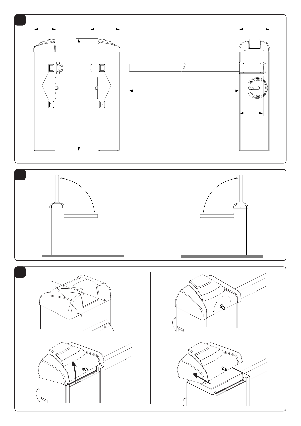
DIMENSIONS
FIG.1
Overall dimensions are expressed in mm.
The road barrier length ranges from 3m minimum to 5m
maximum.
As about 25cm are required to x a road barrier, a useful
opening of passage, ranging from 2.75m to 4.75, will be
available, as shown in Fig.1
Optional accessories can be tted onto be barrier (photo-
cells, selector, etc.). For assembly, apply the special covers
supplied (Rif. A).
RIGHT/LEFT-HAND OPENING OF THE BARRIER
FIG.2
The EVA 5 road barrier is available in both right (EVA5-DX)
and left (EVA5-SX) models.
With reference to Fig.2, a right-hand opening road barrier is
a system which, seen from the door side, closes the right-
hand side of the passage. The left-hand opening is in the
opposite way.
As the opening side can be changed at any moment, it is
advisable to buy a type of road barrier which allows the ea-
siest and rapid installation.
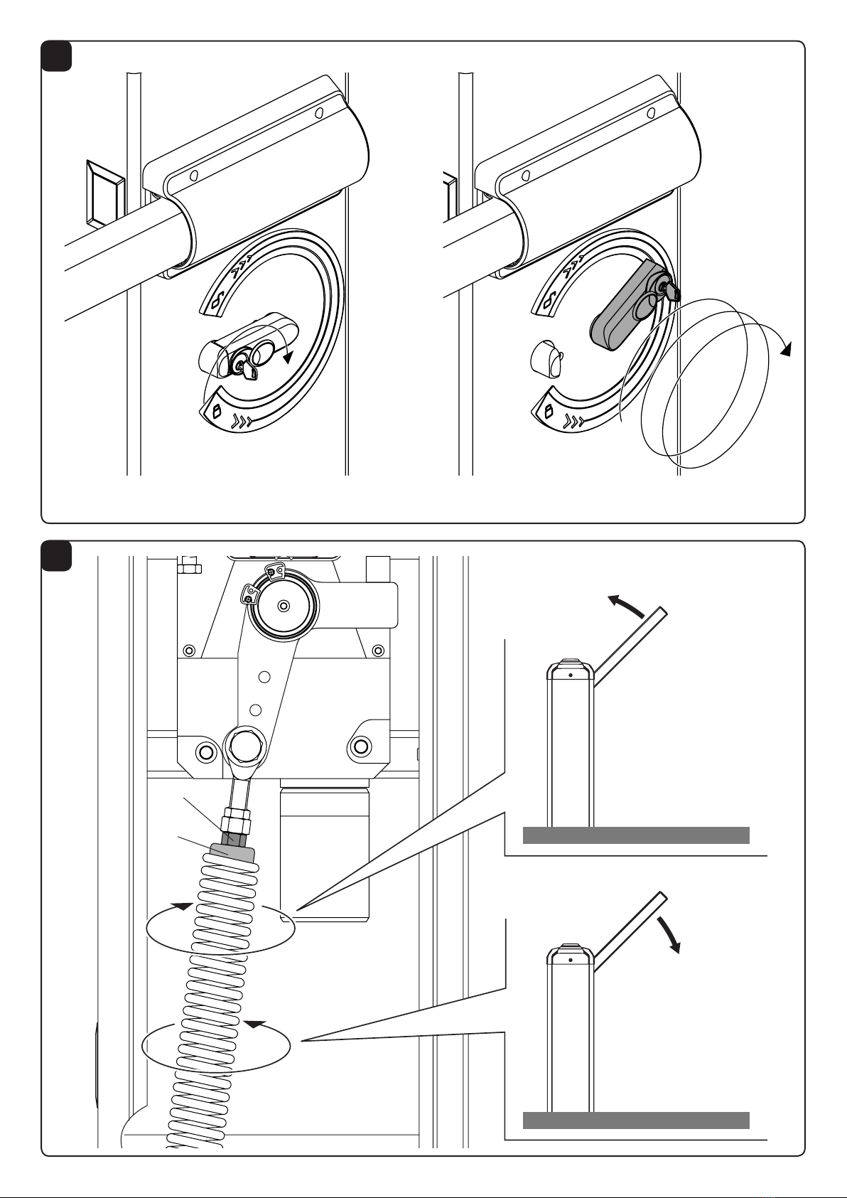
OPENING
FIG.3
The access to the electric and mechanical components of
the road barrier is protected by a lock with customized key.
Proceed as follows:
1 loosen the two nuts D
2 introduce the key in the lock on the side of the door and
turn it anti-clockwise
3 lift the front cover
4 remove the cover
By removing the front door it is now possible to reach both
the control unit, that is placed under the cover, and the
mechanical parts of the road barrier.
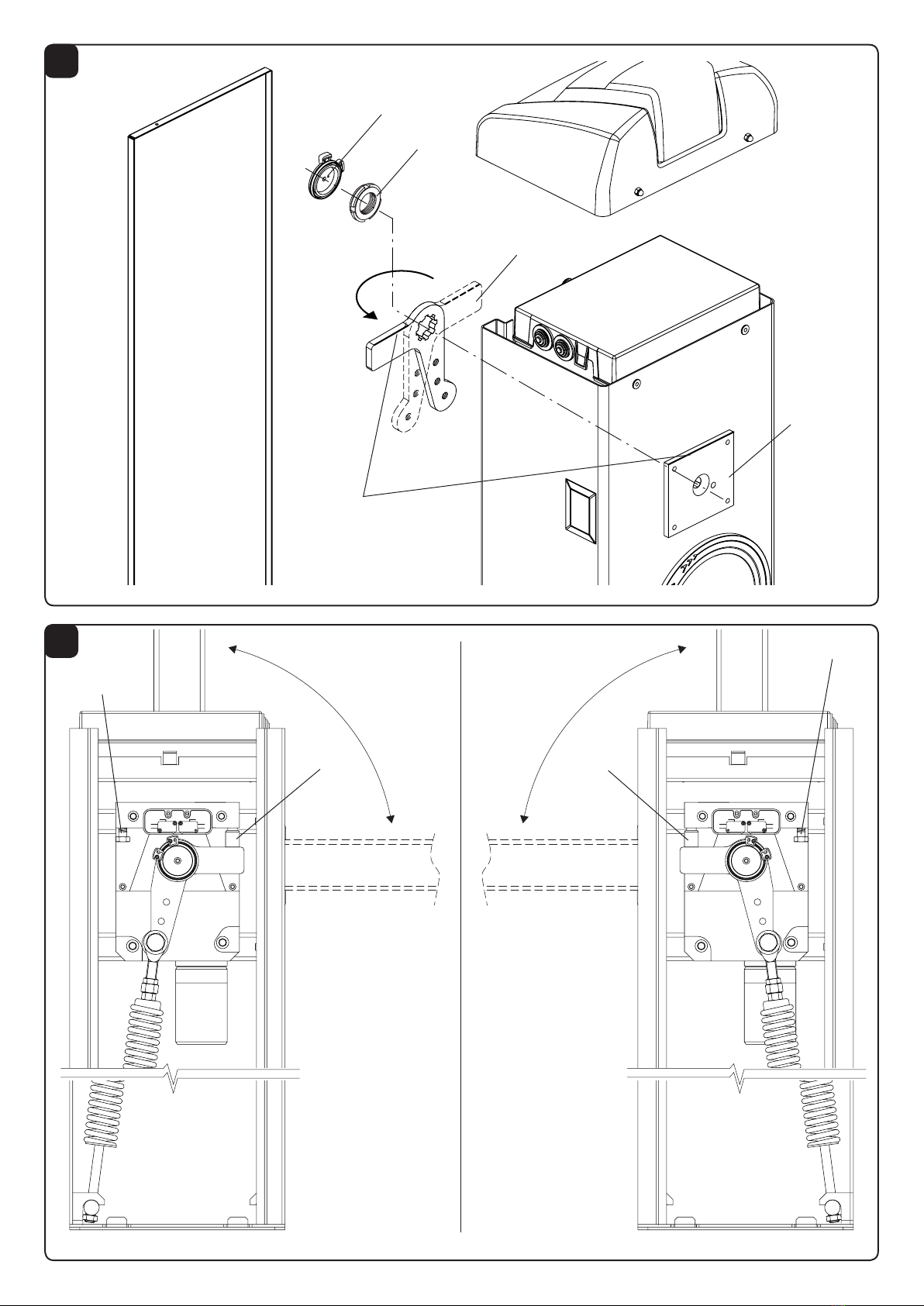
INSTALLATION OF THE FOUNDATION PLATE
FIG.4
After preparing the cable laying (mains power supply, acces-
sories, etc.), place the foundation plate keeping to dimensions
indicated.
Brackets to be cemented are supplied with the system (ref.
S). The brackets must be tted to the foundation plate by
means of 4 screws M12x50 (ref. V).
Check that the foundation plate is perfectly at (ref. L), then
x the road barrier by means of nuts D and corresponding
washers R.
POSITIONING OF THE SPRING
AND ACCESSORIES
FIG.5
According to the length of the beam and the type of accesso-
ries installed, before tensioning the spring, the correct point
to hook the spring to the lever must be selected.
The correct hooking point (“A”, “B” and “C”), must be se-
lected by taking account of table 1, according to the beam
length and the type of accessories to be installed.
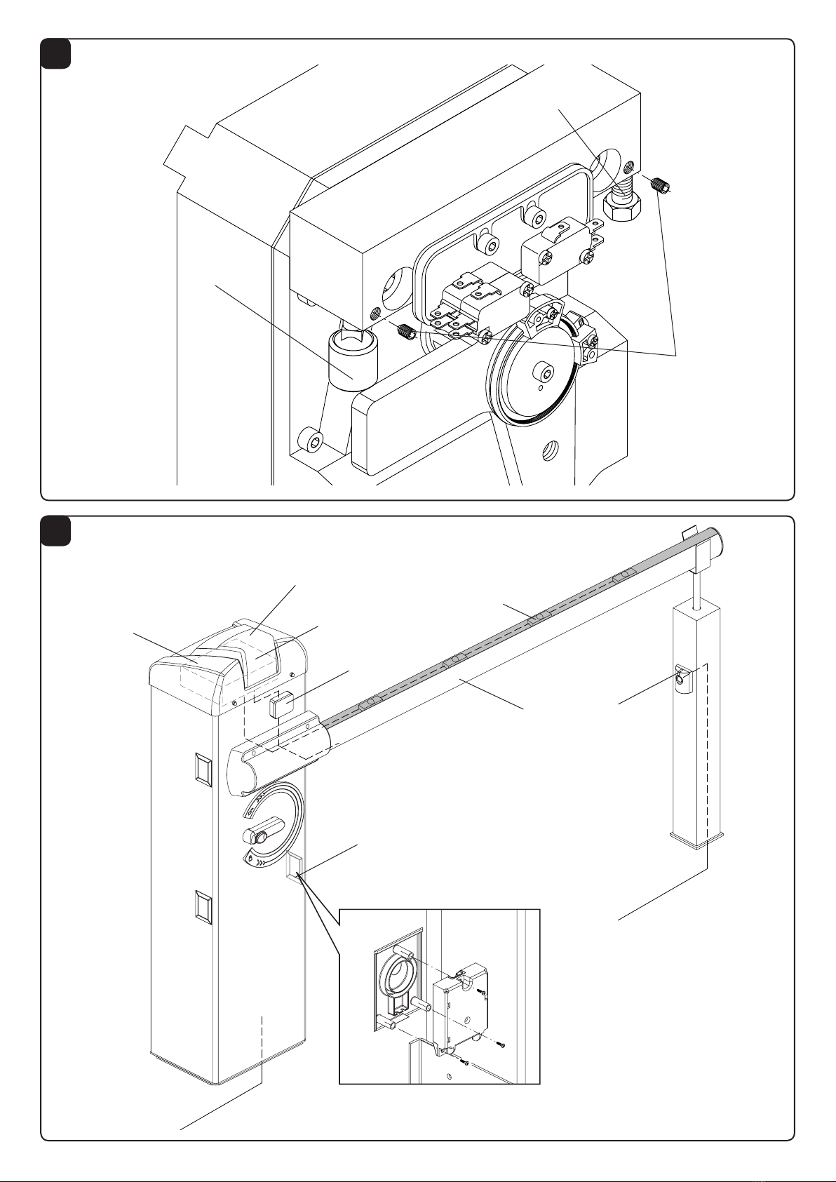
HOW TO FIX THE BEAM
FIG.6
Any accessories for the beam (protection edges, lights, pneu-
matic safety edges, rack, etc. ) are installed before tting the
beam. See relevant instructions.
Fit the beam to plate P by using bracket S and both the 6
screws with the corresponding washers, and plate T.
Apply the removable plastic cover C.

14
15
PREPARATION OF A RIGHT-HAND OR
LEFT-HAND ROAD BARRIER
FIG.7-8
If it is necessary to modify the opening direction of the road
barrier from right-hand to left-hand, or viceversa, proceed
as follows:
• totally unload the spring and unhook it from the anchoring
lever “L”
• remove the limit switch disc (g.7 ref F)
• loosen the lock ring nut (g.7 ref G)
• remove the spring anchoring lever (g.7 ref L) and place
it opposite the previous position
• check alignment (g.7 ref R) between the tting plate “P”
and the anchoring lever “L”
• taking Fig. 8 as a reference, invert the position of the
mechanical stoppers “F1” and “F2”. Loosen the cor-
responding lock grains before loosening the stoppers
(see paragraph ADJUSTENT OF MECHANICAL STOP-
PERS)
• hook the spring in the new position. Fig. 9 shows the
differences between a right-hand road barrier and a left-
hand one.
• in the control unit, invert the wires of motor, as well
as SWC limit switch (closing limit switch) and SWC-R
limit switch (closure braking limit switch).
EMERGENCY MANUAL OPERATION
FIG.9
Should a power failure occur or in the event of faults in the
system, the beam can be released and moved by hand:
• Introduce the customized key in the release lever and turn
it clockwise.
• Turn the release lever clockwise until the beam is released
and it can be opened and closed by hand.
• To reset the automatic operation, turn the lever anti-
clockwise until the beam is released. Reset the initial
position.
TAB.1
EVA 5
Bar length (m)
Accessories for use 3 3,5 4 4,5 5
EVA5.A C C B B A
EVA5.A + VE.RAST C B B A A
EVA5.A + VE.AM C C B B A
EVA5.A + VE.RAST + VE.AM C B B A A
EVA5.A + SC.RES C B B A A
EVA5.A + SC.RES + VE.AM C B B A A
Key
EVA5.A Shank with rubber and upper prole.
VE.RAST Aluminium skirt.
VE.AM Mobile support for bar.
SC.RES Sensitive resistive edge (complying with annexe 4
of the Machines Directive).
Attention:
The installation of the VE.RAST interferes with the use of the SC.RES and vice
versa.
The installation of the EVA.L lights kit does not inuence the balancing of the bar
BALANCING
FIG.10
For a good operation of the road barrier, the beam must be
suitably balanced by the spring.
To check the correct balancing, proceed as follows.
• Check that the spring is correctly hooked to the lever (see
table 1).
• Mechanically release the road barrier through the release
key.
• The road beam, correctly balanced, should remain still in
any position:
- if it tends to open, reduce the spring tension
- if it tends to close, increase the spring tension
The spring tension can be adjusted by tightening (anti-
clockwise rotation) or loosening (clockwise rotation) the
spring by hand. Once the spring tension is adjusted, lock
it by moving the nut “D” in contact with cap T.
MOVEMENTS AND OPERATING TIME
During opening as per Fig. 11:
Starting from the closing position “C”, the beam starts its
opening until it reaches the “SWO-R” point, where the ope-
ning limit switch triggers. The opening speed can be adjusted
through the control unit.
The beam moves for the remaining space (as shown in Fig.11)
at a reduced speed, for a time preset by the control unit.
Therefore, the barrier reaches point A, by completing the
opening movement.
During closure, as per Fig. 12:
The beam starts moving from the opening point “A” and stops
at “SWC-R “ point, when the braking limit switch triggers. The
closing speed can be preset through the control unit.
After activation of the braking limit switch, the braking cycle
starts, ending only when the closing limit switch “C” trig-
gers.
The control unit checks the activation of the “SWC” limit
switch and it is able to automatically offset any changes due
to different weather conditions, for example.
The braking angle shown in Fig.12 is xed at around 25°.
Adjustments of the limit switch cams, trimmers and dip-
C
B
A

14
15
switches should be carried out by referring to these opera-
ting principles.
ADJUSTMENT OF LIMIT SWITCH CAMS
FIG.13
The adjustment of the limit switch cams allow for the fol-
lowing:
Cam O
To advance or delay the starting of braking in the opening
phase (Fig.12 - “SWO-R” point).
Cam C
To previously adjust the stop point in the closing phase
(Fig.13 - “C” point).
Note: before activating the closing limit switch, the cam C
starts braking by triggering the limit switch (Fig.13 - point
“SWC-R”).
Adjust cams by referring to Fig.13:
• Loosen screw V of cam tting.
• Move the opening or closing cam in the desired position.
• Tighten the tting screw V of the cam.
HOW TO ADJUST THE MECHANICAL STOP-
PERS
FIG.14
After the motor stop, the inertial movement of the beam is
blocked thanks to adjustable mechanical stoppers.
After adjusting the opening/closing limit switch cam, move
the related closing mechanical stopper against the lever.
The opening mechanical stopper F2 is of the amortized
type.
By taking Fig.14 as a reference:
• Loosen the lock grain G
• Tighten/loosen the mechanical stop until the desired ac-
tivation position is reached
• Tighten the lock grain
Should an opening direction reversion is required, the position
of the stoppers must be inverted.
WIRE DIAGRAM
FIG.15
This gure shows an installation example of road barrier with
its main accessories.
KEY
1 DA.24V control unit
2 Receiver photocell
3 Transmitter photocell
4 Emergency batteries that can be installed inside the con-
tainer of the control unit
5 EVA:LAMP ashing light card
6 SC.RES pneumatic safety edge
7 SC.E circuit of interface SC.RES/DA:24V
To install and connect the various accessories, see related
instructions.
WARNING
The RC product insurance policy, which covers any injuries
or damages to objects caused by manufacturing defects,
requires the use of Benincà’s original accessories.

32
33
SAFETY MEASURES
• Do not stand within the gate movement area.
• Children must not play with controls and near the gate.
• In the event of malfunctions, do not attempt to repair the failure but contact the specialised personnel.
MANUAL AND EMERGENCY MANOEUVRE
Should a power failure occur or in the event of faults in the system, the beam can be released and moved by hand:
• Introduce the customized key in the release lever and turn it clockwise.
• Turn the release lever clockwise until the beam is released and it can be opened and closed by hand.
• To reset the automatic operation, turn the lever anti-clockwise until the beam is released. Reset the initial position.
MAINTENANCE
• Every month check the good operation of the emergency manual release.
• It is mandatory not to carry out extraordinary maintenance or repairs as accidents may be caused.These operations
must be carried out by qualied personnel only.
• The operator is maintenance free but it is necessary to check periodically if the safety devices and the other components
of the automation system work properly. Wear and tear of some components could cause dangers.
WASTE DISPOSAL
If the product must be dismantled, it must be disposed according to regulations in force regarding the differentiated waste
disposal and the recycling of components (metals, plastics, electric cables, etc..). For this operation it is advisable to call
your installer or a specialised company.
WARNING
All Benincá products are covered by insurance policy for any possible damages to objects and persons caused by con-
struction faults under condition that the entire system be marked CE and only Benincá parts be used.
EVA5
USER’S HANDBOOK

Ref. EVA5
Code Note
1 9686110
29686112
3 9686111
4 9686107
5 9686109
6 9686555
7 9686247
1
6
76
3
2
4
5

Ref. EVA5
Code Note
1 9686428
2 9686429
3 9686430
4 9686431
5 9686432
6 9686433
7 9686434
8 9686435
9 9686436
10 9686190
11 9686248
12 9686160
13 9686437
14 9686666
15 9686185
16 9686438
17 9686120
17 1
2
3
9
8
15
7
4
6
14
16
13
12
11
10
5

AUTOMATISMI BENINCÀ SpA - Via Capitello, 45 - 36066 Sandrigo (VI) - Tel. 0444 751030 r.a. - Fax 0444 759728
Other manuals for EVA 5
3
Table of contents