Solar-Log 200 User manual
1
Installation manual V.3.5.2
Solar-Log™
EN

2
Publisher:
Solare Datensysteme GmbH
Fuhrmannstr. 9
72351 Geislingen-Binsdorf
Germany
International support
Tel.:+49 7428 9418 -640
Fax:+49 7428 9418 -280
e-mail: [email protected]
Italy
Technical support: +39 0471 631032
e-mail: [email protected]
France
Technical support: +33 97 7909708
e-mail: [email protected]
Switzerland
Technical support: +41 565 355346
e-mail: switzerland-[email protected]
United States
Technical support: +1 203 702 7189
e-mail: [email protected]

3
Table of Contents
1 Introduction.................................................................................................................... 9
2 Notes for the Firmware Update............................................................................ 10
3 Updating from Firmware 2.x to 3.x........................................................................11
4 Safety information ......................................................................................................12
4.1 Target group for this manual................................................................................................................................. 12
4.2 Hazard Classes ............................................................................................................................................................ 13
5 Electric current.............................................................................................................14
6 Package contents........................................................................................................15
7 Wall mounting ..............................................................................................................16
8 Unit connections..........................................................................................................18
8.1 Solar-Log 300 / Solar-Log 250............................................................................................................................ 18
8.2 Solar-Log 1200........................................................................................................................................................... 20
8.3 Solar-Log 2000 ......................................................................................................................................................... 22
9 Optional Connections...............................................................................................24
9.1 Solar-Log™ GPRS ...................................................................................................................................................... 24
9.2 Solar-Log™ Meter (Solar-Log 300 and 1200) ................................................................................................ 25
9.3 Solar-Log™ PM+......................................................................................................................................................... 28
10 Connector Assignments and Wiring...................................................................29

4
10.1 Notes on wiring the connections........................................................................................................................ 29
10.2 RS485-A (only Solar-Log 1000, 1200 and 2000) ....................................................................................... 30
10.3 RS485/422 - B............................................................................................................................................................. 31
10.4 RS485/422 - C (only Solar-Log 2000) ............................................................................................................. 32
10.5 S0 ................................................................................................................................................................................... 33
10.5.1 S0 OUT IN (S0-OUT and S0-IN) .......................................................................................................................... 33
10.5.2 S0-IN ...............................................................................................................................................................................34
10.6 PM+................................................................................................................................................................................. 35
11 Connecting the inverters.........................................................................................36
11.1 Switch o the inverters and the Solar-Log™. ................................................................................................. 37
12 Connecting accessories ...........................................................................................38
12.1 Sensor Box Basic and Professional .................................................................................................................... 38
12.2 Sensor Box Professional Plus................................................................................................................................ 40
12.3 Ripple Control Receiver.......................................................................................................................................... 43
12.4 Large External Displays .......................................................................................................................................... 44
12.5 External power meter.............................................................................................................................................. 46
12.6 Wiring for S0 meter ................................................................................................................................................. 48
12.7 Wiring for RS485 meter ......................................................................................................................................... 50
12.8 Installation Utility Meter / Janitza UMG 104 (only Solar-Log 1000 and 2000) ................................ 53
12.9 Solar-Log™ Smart Relay Box ................................................................................................................................ 57
12.10 WeMo Insight Switch ............................................................................................................................................... 59
12.11 Allnet Network Power Socket ............................................................................................................................. 60
13 Other connections .....................................................................................................62
13.1 Alarm contact (only Solar-Log 1000 and 2000).......................................................................................... 62
13.2 Relay (only Solar-Log 1000, 1200 and 2000)................................................................................................ 63
13.3 USB................................................................................................................................................................................. 64
14 Installation.....................................................................................................................65
14.1 Connecting the Solar-Log™ to a network / PC.............................................................................................. 65
14.1.1 Instructions for connection through the PowerLine package ..................................................................66
14.2 Initial installation Solar-Log 200, 250 and 300............................................................................................. 66
14.2.1 Carrying out the initial set up of the Solar-Log 200, 250 and 300........................................................ 67
14.3 Initial set up of the Solar-Log 1200.................................................................................................................... 67
14.3.1 Carrying out the initial set up of the Solar-Log 1200 ..................................................................................68
14.4 Initial installation Solar-Log 1000 and 2000.................................................................................................. 68
14.4.1 Carrying out the initial set up of the Solar-Log 2000.................................................................................68
14.5 Starting the configuration ..................................................................................................................................... 69
14.6 Using the browser menu ......................................................................................................................................... 71

5
15 Main menu.....................................................................................................................73
16 Configuration Menu...................................................................................................74
16.1 Configuring network settings............................................................................................................................... 74
16.2 Ethernet ........................................................................................................................................................................ 75
16.3 GPRS (only Solar-Log™ GPRS) ............................................................................................................................ 76
16.3.1 General Information about GPRS Devices........................................................................................................ 79
16.4 WiFi (only Solar-Log WiFi).................................................................................................................................... 80
16.5 Proxy .............................................................................................................................................................................. 82
17 Internet Configuration ..............................................................................................83
17.1 Access type ................................................................................................................................................................. 83
17.2 Portal.............................................................................................................................................................................. 83
17.3 E-mail............................................................................................................................................................................. 84
17.4 Text message (SMS)................................................................................................................................................. 85
17.5 Export ............................................................................................................................................................................ 86
17.6 Backup........................................................................................................................................................................... 86
18 Configuring connected devices............................................................................87
18.1 Device definition........................................................................................................................................................ 87
18.1.1 Configuring the device interface.......................................................................................................................... 87
18.2 Defining the Solar-Log™ Meter (only Solar-Log™ Meter) .......................................................................... 90
18.3 Device Detection....................................................................................................................................................... 93
18.4 Configuring devices ................................................................................................................................................. 94
18.4.1 Configuring inverters................................................................................................................................................94
18.4.2 Configuring power meters...................................................................................................................................... 95
18.4.3 Configuring sensors ..................................................................................................................................................96
18.4.4 Module Fields, Power Output and Descriptions ...........................................................................................96
18.4.5 Configuring EGO Smart Heaters......................................................................................................................... 97
18.4.6 Configuring IDM Heat Pumps............................................................................................................................... 98
18.4.7 Keba-Stromladestation konfigurieren................................................................................................................99
18.4.8 Module Fields.............................................................................................................................................................. 101
18.5 Changing the device order................................................................................................................................... 101
18.6 Battery......................................................................................................................................................................... 102
19 Configuring Plant Data...........................................................................................103
19.1 General ........................................................................................................................................................................ 103
19.2 Plant groups.............................................................................................................................................................. 104
19.3 Graphic........................................................................................................................................................................ 104
19.4 Defining the PV plant's forecast data ............................................................................................................. 105
19.5 Defining the Feed-in tari ................................................................................................................................... 106

6
20 Configuring Notifications ........................................................................................109
20.1 Recipient........................................................................................................................................................................ 109
20.2 Device notifications.................................................................................................................................................... 110
20.3 Yield.................................................................................................................................................................................. 112
20.4 Alarm (only Solar-Log 1000 and 2000)..................................................................................................................... 113
20.5 Power & Failure............................................................................................................................................................ 113
20.6 PM ..................................................................................................................................................................................... 115
21 Editing Data................................................................................................................... 116
21.1 Initial yield...................................................................................................................................................................... 116
21.2 Data correction ............................................................................................................................................................ 117
21.3 System backup............................................................................................................................................................. 117
21.4 Backup............................................................................................................................................................................. 119
21.5 Reset ................................................................................................................................................................................ 121
22 System Configuration ............................................................................................... 123
22.1 Access control............................................................................................................................................................. 123
22.2 Language/Country/Time......................................................................................................................................... 124
22.3 Display............................................................................................................................................................................ 126
22.4 Licenses .......................................................................................................................................................................... 127
22.5 Firmware......................................................................................................................................................................... 127
23 Smart Energy ...............................................................................................................130
23.1 Defining Smart Energy Switching........................................................................................................................ 130
23.2 Smart Energy Switching Groups........................................................................................................................... 131
23.2.1 Creating switching groups....................................................................................................................................... 132
23.2.2 Configuring switching groups................................................................................................................................ 135
23.3 Smart Energy Surplus Management.................................................................................................................... 141
24 Feed-In Management................................................................................................ 143
24.1 Plant parameters ........................................................................................................................................................ 143
24.2 Active power................................................................................................................................................................ 145
24.2.1 Active power deactivated........................................................................................................................................146
24.2.2 Remote controlled active power reduction (only Solar-Log™ PM+).......................................................146
24.2.3 Remote controlled active power reduction with the calculation of self-consumption (only Solar-
Log™ PM+)...................................................................................................................................................................149
24.2.470% fixed reduction ...................................................................................................................................................149
24.2.5 70% Fixed reduction with the calculation of self-consumption ...............................................................150
24.2.6 Adjustable reduction .................................................................................................................................................. 151
24.2.7 Adjustable Reduction with the Calculation of Self-Consumption............................................................. 151
24.2.8 Fixed reduction in watts........................................................................................................................................... 152
24.2.9 Fixed reduction in watts with the calculation of self-consumption ........................................................ 152
24.2.10 Percentage of consumption for an adjustable reduction ......................................................................... 152

7
24.3 Reactive Power ........................................................................................................................................................... 153
24.3.1 Reactive power deactivated ................................................................................................................................... 153
24.3.2 Fixed value cos (Phi) shift factor ..........................................................................................................................154
24.3.3 Fixed reactive power in Var ....................................................................................................................................154
24.3.4Variable cos (Phi) shift factor over characteristic curve P/Pn................................................................... 156
24.3.5 Variable reactive power via the characteristic curve Q(U)
(only Solar-Log 2000 with Utility Meter)................................................................................................................157
24.3.6 Remote-controlled fixed value cos (Phi) shift factor only Solar-Log™ PM+) ......................................... 159
24.4 Linking (only Solar-Log 1000 and 2000).......................................................................................................... 161
24.5 Profile.............................................................................................................................................................................. 162
25 Direct Marketing .........................................................................................................164
26 Direct Device Configurations (Solar-Log 1200 and 2000)..................................................... 166
26.1 Display menu structure............................................................................................................................................ 166
26.2 Control Elements on the Display.......................................................................................................................... 167
26.3 Settings on the device ............................................................................................................................................. 167
26.4 Start menu (only Solar-Log1200) ........................................................................................................................ 167
26.4.1 Initial configuration (only Solar-Log 1200) ......................................................................................................168
26.5 Device Detection (only Solar-Log 1200)............................................................................................................ 172
26.5.1 Easy Installation (only Solar-Log 1200).............................................................................................................. 173
26.6 Basic settings menu ................................................................................................................................................... 174
26.6.1 Basic Settings | Network menu.............................................................................................................................. 174
26.6.2 Basic Settings | Portal menu................................................................................................................................... 175
26.7 USB menu ...................................................................................................................................................................... 175
26.8 Advanced settings menu ........................................................................................................................................ 177
26.9 Error and Fault Messages on the Display ......................................................................................................... 182
27 Notifications on the LCD Status Display (Solar-Log 250, 300, 1200 and
2000).............................................................................................................................. 183
27.1 Meaning of the symbols on the LCD display................................................................................................... 183
27.1.1 Fault messages ............................................................................................................................................................ 185
27.2 Notifications on the LCD display ......................................................................................................................... 186
27.3 Normal operation ....................................................................................................................................................... 186
27.4 Power reduction ......................................................................................................................................................... 186
28 Faults............................................................................................................................... 187
28.1 Restarting and resetting.......................................................................................................................................... 187
28.1.1 Reset buttons ............................................................................................................................................................... 187
28.1.2 Reset ................................................................................................................................................................................ 187

8
28.1.3 Restoring the factory settings .................................................................................................................................. 188
28.1.4 Rebooting and Resetting via the web menu....................................................................................................... 189
28.2 Fault messages .............................................................................................................................................................. 190
28.2.1 Fault messages GPRS...................................................................................................................................................190
28.2.2 Fault messages time ...................................................................................................................................................... 191
28.2.3 Fault messages WiFi...................................................................................................................................................... 191
28.2.4 Fault messages Internet............................................................................................................................................. 192
28.2.5 Fault messages Export to External Server and Backup ................................................................................ 193
28.2.6 Fault message e-mail transfer.................................................................................................................................. 195
28.2.7 Portal Transfer Fault messages ............................................................................................................................... 197
28.2.8 Fault messages Feed-in Management.................................................................................................................. 197
28.2.9 Special cases .................................................................................................................................................................. 198
29 Disposal............................................................................................................................ 199
30 Technical Data ..............................................................................................................200
31 Appendix ........................................................................................................................204
31.1 Internet ports................................................................................................................................................................. 204
31.2 Country specific inverter detection with Easy Installation. ......................................................................... 205
31.3 Wiring meters to record self-consumption........................................................................................................ 206
31.3.1 Meter connection options to record the total consumption via an RS485/S0 interface.................206
31.3.2 Meter connection options for bi-directional recording of the total consumption via only an RS485
interface. ........................................................................................................................................................................ 207
31.4 Connection examples for ripple control receivers .......................................................................................... 208
31.4.1 Variation with 4 relays (ENBW >100kWp).........................................................................................................209
31.4.2 Variation with two relays...............................................................................................................................................211
31.4.3 Variation with three relays.......................................................................................................................................... 213
31.4.4 Variation with 5 relays (including emergency stop)......................................................................................... 215
31.5 Digital Interfaces ............................................................................................................................................................ 217
31.5.1 Modbus TCP ....................................................................................................................................................................217
31.6 Live data compact – summarized (complete plant)......................................................................................... 218
31.6.1 JSON Interfaces.............................................................................................................................................................. 219
31.7 Dimensions ...................................................................................................................................................................... 221
32 List of Figures ................................................................................................................222

9
Introduction
1 Introduction
This installation manual is intended for use by solar energy technicians and professional electricians.
User manuals are available for operating the Solar-Log™.
The wiring for the inverters is described in detail in the Component Installation Manual.
The Solar-Log™ must only be used by persons who have fully read and understood this installation manual
before installing, operating and/or servicing the device.
Our product documentation is being constantly updated and expanded.
The current versions of the documents can be downloaded from our website:
www.solar-log.com.
The descriptions in this manual refer to firmware version 3.5.2

10
Notes for the Firmware Update
2 Notes for the Firmware Update
The following models may be updated to the Solar-Log Firmware Version 3.5.2:
• Solar-Log 200
• Solar-Log 250
• Solar-Log 300
• Solar-Log 500
• Solar-Log 1000
• Solar-Log 1200
• Solar-Log 2000

11
Updating from Firmware 2.x to 3.x
3 Updating from Firmware 2.x to 3.x
The following note is for the Solar-Log 200, 500 and 1000 models when updating to firmware version 3.x.
In order to update to 3.x, the Solar-Log™ must at least be running firmware version 2.x. The latest firmware
can be downloaded from our website:
http://www.solar-log.com/de/service-support/firmware.html.
Note!
After installing firmware 3.x, it is no longer possible to downgrade to the previous ver-
sions. It is not possible to install older firmware versions.
The following changes occur when upgrading to 3.x:
• The data transfer function is no longer available.
• The Smart Energy section has been completely revised. If the function External Switch (only Solar-
Log 1000) is used, this part needs to be reconfigured after the update.
• The settings and function of the power management have to be checked and, if need be, reconfig-
ured.
• With the new modern web interface, old web browsers might sometimes cause problems with the
functionality. We recommend using the current version of Mozilla's Firefox, Google's Chrome, Mi-
crosoft Edge or Microsoft's Internet Explorer.
As part of the update, the Solar-Log™ has a data reformatting process running in the background. This
process starts once the update is finished. This process could last several hours and the Solar-Log™ will
operate and react slower until the update finishes.

12
Safety information
4 Safety information
4.1 Target group for this manual
In order to protect people, the product itself, and other equipment, please pay attention to the following
before handling the product:
• the content of this manual,
• the safety information,
• the warning signs and type plates attached to the product.
This manual is intended for solar energy technicians and qualified electricians who are installing a
Solar-Log 250 (read the additional information below), 300, 1200 and 2000, wiring them to inverters, con-
figuring them to operate in particular systems, and putting them into operation.
All the actions described in this manual for wiring and working on inverters must be carried out only by
specially trained electricians. All repairs should only be carried out by similarly trained personnel, or by the
manufacturers themselves.
Solare-Datensysteme GmbH is not liable for any personal injuries, property damages and system malfunc-
tions and their consequences which result from not adhering to the product documentation.
Note!
The Solar-Log 300 functions described in this manual are essentially identical to
those of the Solar-Log 250. Refer to the Solar-Log 250 data sheet for the differ-
ences.

13
Safety information
4.2 Hazard Classes
The safety instructions in this document are represented with standard signs and symbols. Two classes of
risk are identified, depending on their probability of occurrence and the seriousness of their consequences.
Danger!
Indicates an imminently hazardous situation to life
Non-compliance with this warning can lead to severe and irreversible injuries or death
Caution!
Indicates an imminently hazardous situation to people, or a risk of material damage
Non-compliance with this warning can lead to irreversible injuries or to material dam-
age.
14
Electric current
5 Electric current
Danger!
Risk of death by electric shock if inverters are opened.
Never open the inverter housing when the inverter is connected to power.
See Switching off the inverters on page 37.
Always read the installation and safety instructions given in the manual for the corre-
sponding inverter.
Danger!
Danger of death if there is condensation in the power supply unit when started!
Condensation can occur if the power supply unit is moved directly from a cold environ-
ment to a warm environment.
Wait until the temperatures have equalized before doing this.
Caution!
Damage to the electrical components in inverters and on interface cards due to elec-
trostatic discharge.
Avoid contact with component connections and plug contacts.
Before picking up the component, ground yourself by holding the protective conduc-
tor (PE) or the unpainted part of the inverter housing.
Caution!
Damage to the electrical components of the Solar-Log™ due to the wiring of the Solar-
Log™!
Switch the Solar-Log™ off;
See Chapter 11.1 on page 37
Caution!
Risk of electric shock.
Do not use the unit if the housing of the external power supply unit is damaged. A
damaged power supply unit must be replaced by one of the same type and from the
same manufacturer in order to avoid danger.
Caution!
The Solar-Log™ may only be used indoors or enclosed spaces.
The device has the protection class IP20.

15
Package contents
6 Package contents
Check the package contents before proceeding to assembly and install.
Report any damage or missing parts to the forwarding agent and dealer immediately.
The unit is supplied with the following components:
• Solar-Log™ basic unit
• 2x cover panels to be fitted to the top and bottom of the unit to protect the connections and reset
button
• 12 V power supply with country-specific adapters
• Terminal block connector for all connections
• 4x wall plugs and screws for wall mounting
• CD with the user manual as a PDF file

16
Wall mounting
7 Wall mounting
The device is produced according to protection class IP20 and is intended only for installation in interior
areas that are dry and dust-free.
Suitable wall plugs and screws are supplied for wall mounting.
Please remember that an electrical outlet and a local network connection are required near the Solar-Log™
in order for it to operate. GPRS and WiFi models do not require the network connection.
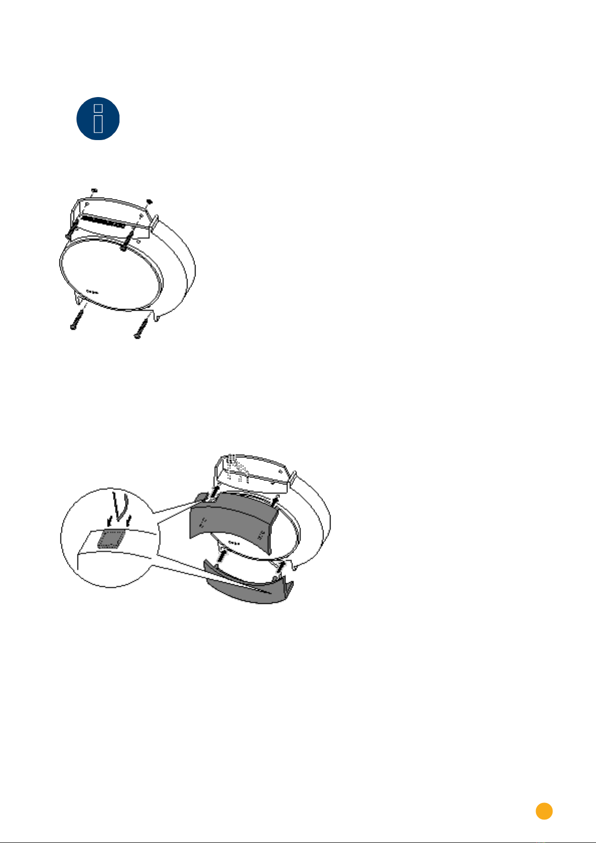
• Put the housing where it is to be fitted and mark the drill holes.
Fig.: Solar-Log™ wall mounting
• The Solar-Log™ should be fitted in an easily accessible place.
• Drill the holes and insert the wall plugs
• The information on dimensions of the case and the mounting points is in chapter 34.6 on page
221
17
Wall mounting
Note! concerning
Solar-Log™ GPRS
The SIM card should be inserted before attaching the unit, as the insertion slot will no
longer be accessible after wall mounting.
• Fasten the housing with the screws
• Cable feed through – top and/or bottom covers.
Using a file or a saw, clear the cable feed holes.
The top and bottom covers are identical.
• Plug all cable connectors into their connections.
• Attach the covers

18
Unit connections
8 Unit connections
8.1 Solar-Log 300 / Solar-Log 250
Top connections
Fig.: Top Connections Solar-Log 300
Solar-Log 300* / Solar-Log 250
S0-Out
S0-IN*
S0 pulse output for connect-
ing to a large external display.
S0 pulse input for connection
to an external power meter.
Please note the connection
characteristics of the S0 con-
nection.
USB USB connection. Suitable for
USB sticks.
Not suitable for a connection
to a PC
S0-IN S0 pulse input for connection
to an external power meter.
*Only the Solar-Log 300 is equipped with this connection.
19
Unit connections
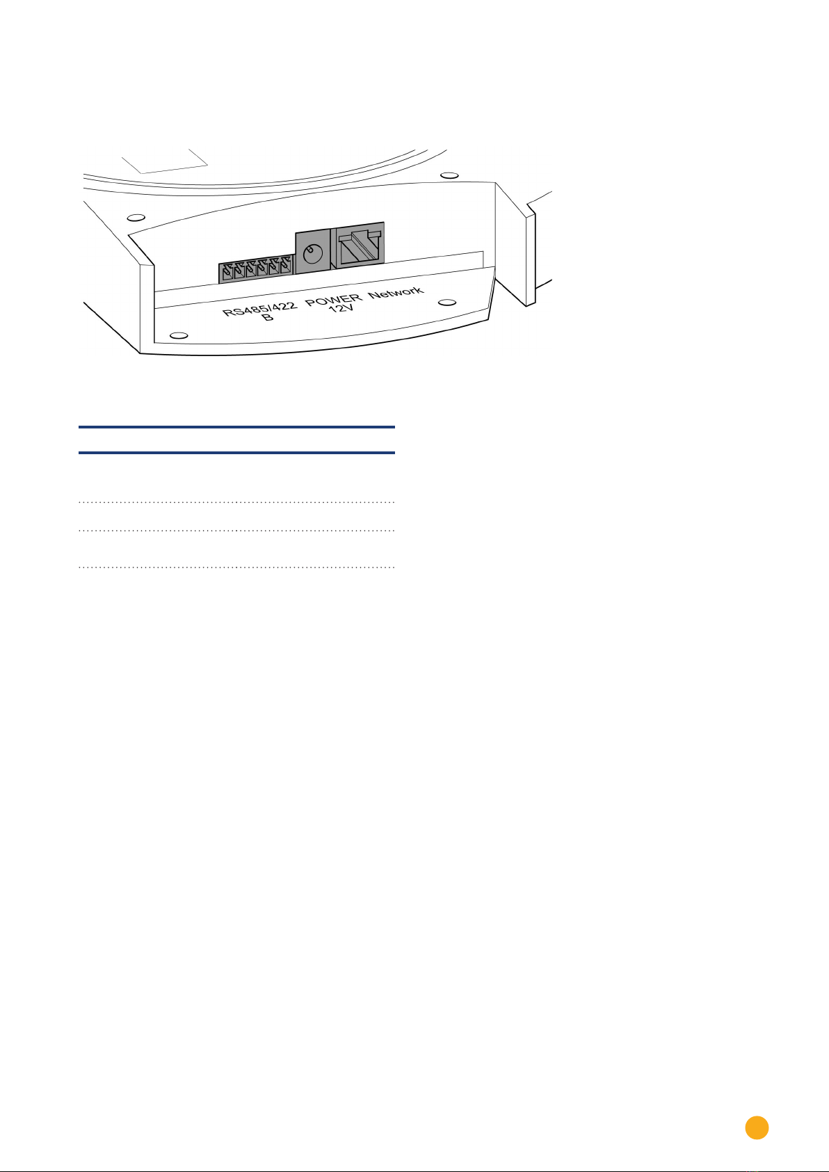
Bottom connections
Fig.: Bottom connections Solar-Log 300
Solar-Log 300 / Solar-Log 250
RS485/422 - B RS485 interface, 6 pin:
Connection for inverters
and additional accessories
Power 12 V 12 volt DC input
Network Ethernet network interface,
10/100 Mbit

20
Unit connections
8.2 Solar-Log 1200
Top connections
Fig.: Top Connections Solar-Log 1200
Solar-Log 1200
S0-Out
S0-IN
S0 pulse output for con-
necting to a large external
display. S0 pulse input for
connection to an external
power meter. Please note
the connection characteris-
tics of the S0 connection.
USB USB connection. Suitable
for USB sticks.
Not suitable for a connec-
tion to a PC
S0-IN S0 pulse input for connec-
tion to an external power
meter.
Other manuals for 200
2
This manual suits for next models
6
Table of contents


