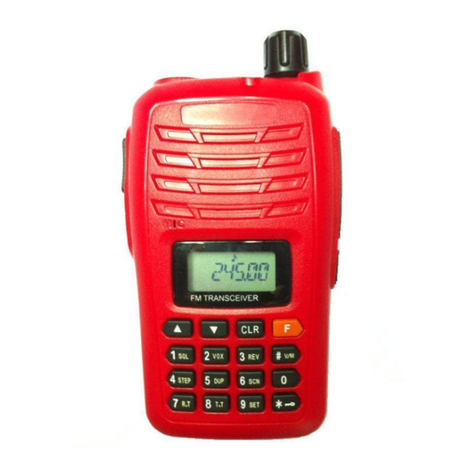
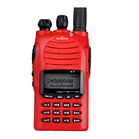
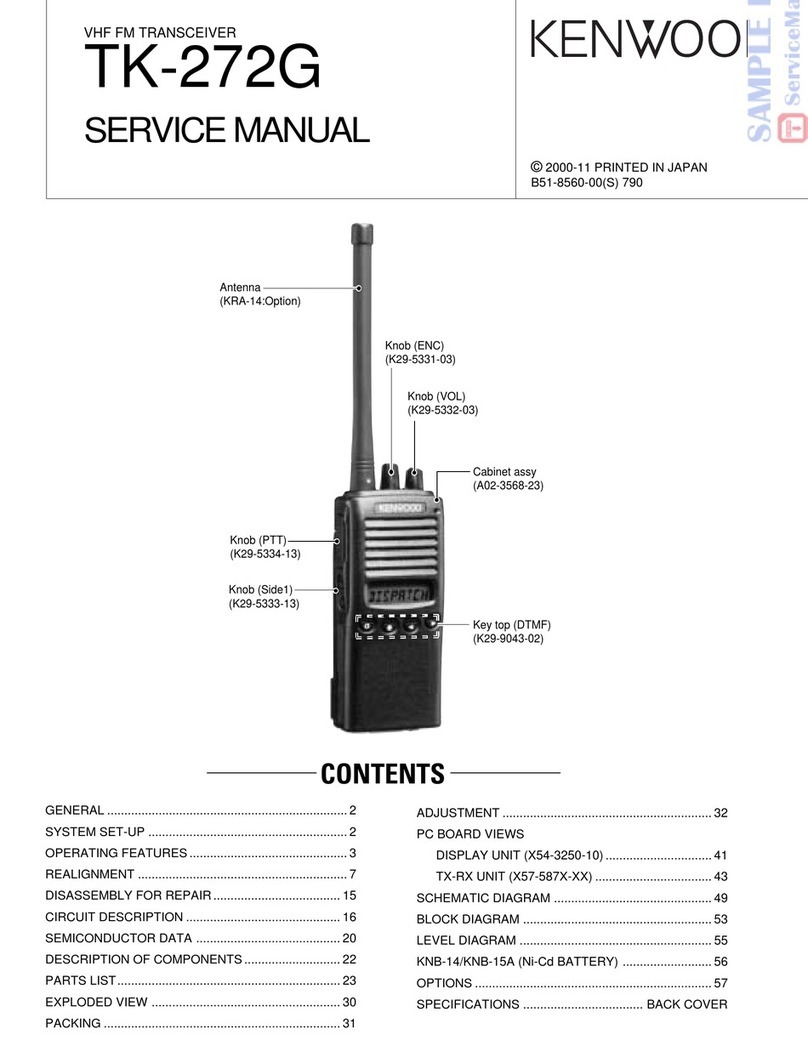
Benison V5 User manual

BENISON V5
BENISON
V5
VHF FM TRANSCEIVERS
Service Manual
- 1 -

BENISON V5
- 2 -
SPECIFICATIONS
GENERAL
. Frequency coverage : 245.0000 ~245.9875 MHz
. Type of emission : 8K50F3E
. Number of channels : 80 ch + 10 ch
. Power supply requirement : 7.2 V DC (negative ground; supplied battery pack)
. Current drain (approx.) : Transmit at High (5.0 W) 1.7 A, at Low (1.0 W) 700 mA
: Receive rated audio 250 mA
: stand-by 70 mA
. Frequency stability : ±0.001 %
. Usable temperature range :-10°C~+60°C
. Dimensions (projections not included) : 54(W)×132(H)×35(D) mm
. Weight (with ant., BP-512) : 370 g ; 13.1 oz.
TRANSMITTER
. RF output power (at 7.2 V DC) : 5 W / 1 W (High / Low)
(with supplied battery pack)
. Modulation system : Variable reactance frequency modulation
. Maximum frequency deviation : ±2.5 kHz
. Spurious emissions : 70 dB typical
. Adjacent channel power : 60 dB typical
. Transmitter audio distortion : Less than 3% at 1 kHz, 40% deviation
RECEIVER
. Receive system : Double conversion superheterodyne system
. Intermediate frequencies : 1st 21.700 MHz / 2nd 450 kHz
. Sensitivity : 0.18 μV at 12 dB SINAD (typical)
. Squelch sensitivity : 0.25 μV at threshold (typical)
. Adjacent channel selectivity : 65 dB (typical)
. Spurious response rejection : 70 dB (typical)
. Intermodulation rejection ratio : 70 dB (typical)
. Hum and noise : 40 dB (typical)
. Audio output power (at 7.2 V DC) : 500 mW typical at 5% distortion with an 8 ohm load
All stated specifications are subject to change without notice or obligation.

BENISON V5
- 3 -
CHANNELS LIST
CH No. FREQ. CH No. FREQ. CH No. FRQ. CH No. FREQ.
1 245.0000 21 245.2500 41 245.5000 61 245.7500
2 245.0125 22 245.2625 42 245.5125 62 245.7625
3 245.0250 23 245.2750 43 245.5250 63 245.7750
4 245.0375 24 245.2875 44 245.5375 64 245.7875
5 245.0500 25 245.3000 45 245.5500 65 245.8000
6 245.0625 26 245.3125 46 245.5625 66 245.8125
7 245.0750 27 245.3250 47 245.5750 67 245.8250
8 245.0875 28 245.3375 48 245.5875 69 245.8375
9 245.1000 29 245.3500 49 245.6000 69 245.8500
10 245.1125 30 245.3625 50 245.6125 70 245.8625
11 245.1250 31 245.3750 51 245.6250 71 245.8750
12 245.1375 32 245.3875 52 245.6375 72 245.8875
13 245.1500 33 245.4000 53 245.6500 73 245.9000
14 245.1625 34 245.4125 54 245.6625 74 245.9125
15 245.1750 35 245.4250 55 245.6750 75 245.9250
16 245.1875 36 245.4375 56 245.6875 76 245.9375
17 245.2000 37 245.4500 57 245.7000 77 245.9500
18 245.2125 38 245.4625 58 245.7125 78 245.9625
19 245.2250 39 245.4750 59 245.7250 79 245.9750
20 245.2375 40 245.4875 60 245.7375 80 245.9875
50 CTCSS TONES SQ. ( Hz )
NO. TONE NO. TONE NO. TONE NO. TONE NO. TONE
1 67.0 11 94.8 21 131.8 31 171.3 41 203.5
2 69.3 12 97.4 22 136.5 32 173.8 42 206.5
3 71.9 13 100.0 23 141.3 33 177.3 43 210.7
4 74.4 14 103.5 24 146.2 34 179.9 44 218.1
5 77.0 15 107.2 25 151.4 35 183.5 45 225.7
6 79.7 16 110.9 26 156.7 36 186.2 46 229.1
7 82.5 17 114.8 27 159.8 37 189.9 47 233.6
8 85.4 18 118.8 28 162.2 38 192.8 48 241.8
9 88.5 19 123.0 29 165.5 39 196.6 49 250.3
10 91.5 20 127.3 30 167.9 40 199.5 50 254.1

BENISON V5
PANEL DESCRIPTION
Switches, controls, keys and Connectors
1: POWER SWITCH [POWER]/CONTROL DIAL [VOL]
Rotate to adjust the volume level, to turn the power ON and OFF.
2:CTCSS SWITCH
Push and hold to force the CTCSS open and set the transceiver
3:PTT SWITCH [PTT]
Push and hold to transmit; release to receive.
4:SQUELCH SWITCH [SQL]
Push and hold to force the squelch open and set the transceiver
to the squelch level adjustable condition.
5:UP/DOWN KEYS
Selects the operating frequency.[UP]/[DN]
6:KEY PAD
Used to enter operating frequency, the DTMF codes, etc.
7:ANTENNA CONNECTOR
Connects the supplied antenna.
8:[SP]/[MIC] JACK
Connect an optional speaker-microphone or headset, if desired.
The internal microphone and speaker will not function when either is connected.
9:FUNCTION DISPLAY
*The assigned function for [SQL] and [DP]/[DN] can be traded in INITIAL SET MODE.
- 4 -

BENISON V5
- 5 -
CIRCUIT DESCRIPTION
1) Receiver System
The receiver system is a double superheterodyne system with a 21.7MHz first IF and a 450kHz second IF.
1. Front End
The received signal at any frequency in the 245.0000- to 245.9875-MHz range is passed through the
low-pass filter (L29, L28, L14, L13,C224, C220, C223,C219 and C222) and tuning circuit (L12 and D27),
and amplified by the RF amplifier (Q29). The signal from Q29 is then passed through the tuning circuit (L9
and L11 varicaps D25 and D26) and converted into 21.7MHz by the mixer (Q28).The tuning circuit, which
consists of L12, L9, varicaps D27 and D26, L11, varicaps D25 , is controlled by the tracking voltage form
the CPU so that it is optimized for the reception frequency. The local signal from the VCO is passed through
the buffer (Q24), and supplied to the source of the mixer (Q28). The radio uses the lower side of the
superheterodyne system.
2. IF Circuit
The mixer mixes the received signal with the local signal to obtain the sum of and difference between them.
The crystal filter (FL3, FL2) selects 21.7MHz frequency from the results and eliminates the signals of the
unwanted frequencies. The first IF amplifier (Q17) then amplifies the signal of the selected frequency.
3. Demodulator Circuit
After the signal is amplified by the first IF amplifier (Q17), it is input to pin 16 of the demodulator IC (IC14).
The second local signal of 21.25MHz (shared with PLL IC reference oscillation), which is oscillated by the
internal oscillation circuit in IC13 and crystal (X4), is input through pin 2 of IC14. Then, these two signals
are mixed by the internal mixer in IC14 and the result is converted into the second IF signal with a
frequency of 450kHz. The second IF signal is output from pin 3 of IC14 to the ceramic filter (FL1), where the
unwanted frequency band of that signal is eliminated, and the resulting signal is sent back to the IC14
through pins 5.The second IF signal input via pin 5 is demodulated by the internal limiter amplifier and
quadrature detection circuit in IC14, and output as an audio signal through pin 9.
4. Audio Circuit
AF signals from the FM IF IC (IC14, pin 9) are applied to the mute switch (IC4, pin 1) via the AF filter circuit
(IC14b, pins 6,7). The output signals from pin 11 are applied to the AF power amplifier (IC9, pin 4) after
being passed through the [VOL] control (W1).The applied AF signals are amplified at the AF power
amplifier circuit (IC9, pin 4) to obtain the specified audio level. The amplified AF signals, output from pin 10,
are applied to the internal speaker (SP1) as the “SP”signal via the [SP] jack when no plug is connected
to the jack.
5. Squelch Circuit
A squelch circuit cuts out AF signals when no RF signals are received. By detecting noise components in
the AF signals, the squelch switches the AF mute switch. A portion of the AF signals from the FM IF IC
(IC14, pin 9) are applied to the active filter section (IC14, pin 8) where noise components are amplified and
detected with an internal noise detector. The active filter section amplifies noise components. The filtered
signals are rectified at the noise detector section and converted into “NOIS”(pulse type) signals at the
noise comparator section. The “NOIS”signal is applied to the CPU(IC6, pin 14). The CPU detects the
receiving signal strength from the number of the pulses, and outputs an “AFB”signal from pin 33. This
signal controls the mute switch (IC4) to cut the AF signal line.
2) Transmitter System
1. MICROPHONE AMPLIFIER CIRCUIT
The microphone amplifier circuit amplifies audio signals with +6 dB/octave pre-emphasis characteristics
from the microphone to a level needed for the modulation circuit. The AF signals from the microphone are
applied to the microphone amplifier circuit (IC1C, pin 10). The amplified AF signals are passed through the
low-pass filter circuit (IC1D, pins 13, 14) via the mute switch (IC4, pins 4, 3). The filtered AF signals are

BENISON V5
- 6 -
applied to the modulator circuit after being passed through the mute switch (IC4, pins 9, 8).
2. MODULATION CIRCUIT
The modulation circuit modulates the VCO oscillating signal (RF signal) using the microphone audio signal.
The audio signals change the reactance of a diode (D7) to modulate an oscillated signal at the VCO circuit
(Q20, Q23).The oscillated signal is amplified at the buffer-amplifiers (Q21,Q24), then applied to the T/R
switching circuit (D9, D10).
3. DRIVE/POWER AMPLIFIER CIRCUITS
The signal from the VCO circuit passes through the T/R switching circuit (D9) and is amplified at the buffer
(Q19),drive (Q27) and power amplifier (Q26) to obtain 5 W of RF power (at 7.2 V DC). The amplified signal
passes through the antenna switching circuit (D11), and low-pass filter and is then applied to the antenna
connector. The bias current of the drive (Q27) and the power amplifier (Q26) is controlled by the APC
circuit.
4. APC CIRCUIT
The APC circuit (IC1A) protects the drive and the power amplifiers from excessive current drive, and
selects HIGH or LOW output power. The signal output from the power detector circuit (D28, D29) is applied
to the differential amplifier (IC1A, pin 2), and the“T1”signal from the expander (IC5, pin 11), controlled by
the CPU (IC8), is applied to the other input for reference. When the driving current is increased, input
voltage of the differential amplifier (pin 2) will be increased. In such cases the differential amplifier output
voltage (pin 1) is decreased to reduce the driving current.
3) PLL Synthesizer Circuit
1. PLL
The dividing ratio is obtained by sending data from the CPU (IC8) to pin 28 and sending clock pulses to pin
39 of the PLL IC (IC13). The oscillated signal from the VCO is amplified by the buffer (Q22) and input to pin
6 of IC13. Each programmable divider in IC13 divides the frequency of the input signal by N according to
the frequency data, to generate a comparison frequency of 12.5kHz.
2. PLL Loop Filter Circuit
If a phase difference is found in the phase comparison between the reference frequency and VCO output
frequency, the charge pump output (pin 8) of IC11 generates a pulse signal, which is converted to DC
voltage by the PLL loop filter and input to the varicap of the VCO unit for oscillation frequency control.
3. VCO Circuit
A PLL circuit provides stable oscillation of the transmit frequency and receive 1st LO frequency. The PLL
output compares the phase of the divided VCO frequency to the reference frequency. The PLL output
frequency is controlled by the divided ratio (N-data) of a programmable divider.The PLL circuit contains the
VCO circuit (Q20, Q23). The oscillated signal is amplified at the buffer-amplifiers (Q21, Q22) and then
applied to the PLL IC (IC11). The PLL IC contains a prescaler, programmable counter, programmable
divider and phase detector, etc. The entered signal is divided at the prescaler and programmable counter
section by the N-data ratio from the CPU. The divided signal is detected on phase at the phase detector
using the reference frequency. If the oscillated signal drifts, its phase changes from that of the reference
frequency, causing a lock voltage change to compensate for the drift in the oscillated frequency. A portion
of the VCO signal is amplified at the buffer-amplifier (Q24) and is then applied to the receive 1st mixer (Q28)
or transmit buffer-amplifier circuit (Q19) via the T/R switching diode (D9, D10).
4) CPU and Peripheral Circuits
1. LCD Display Circuit
The IC10 turns ON the LCD via segment and common terminals with 1/4 the duty and 1/3 the bias, at the
frame frequency is 100Hz.
2. Display Lamp Circuit
When the key is pressed, “H” is output form pin 34 of CPU (IC8) to the bases of Q15. Q15 then turn ON and
the LED (D14 – D22) light.

BENISON V5
- 7 -
3. DTMF Encoder
The CPU (IC8) is equipped with an internal DTMF encoder. The DTMF signalis output from pin 8, through
R75, and through the microphone amplifier (IC1), and is sent to the varicap of the VCO for modulation. At
the same time, the monitoring tone passes through the AF circuit and is output form the speaker.
4. CTCSS Encoder
The CPU (IC8) is equipped with an internal tone encoder, The tone signal (67.0 to 254.3Hz) is output from
pin 9 of the CPU to the varicap (D7) of the VCO for modulation.
5. CTCSS Decoder
The voice band of the AF output signal from pin 10 of IC5 is cut by sharp active filter IC2 (VCVS) and
amplified, then led to pin 4 of CPU. The input signal is compared with the programmed tone frequency code
in the CPU. The squelch will open when they match.
6. Clock Shift
In the unlikely event that CPU clock noise is present on a particular operating frequency programmed into
the radio, you can shift the CPU clock frequency to avoid the CPU clock-noise. The output signal from pin
32 of the CPU turns on D4. Then the oscillation frequency of X2 will be shifted about 300 ppm.

BENISON V5
- 8 -
ADJUSTMENT PROCEDURES
Note:
It is assumed that the unit is supplied with a regulated 8.4 volts during the adjustment procedure. Do not
use a metal screw driver to adjust the ferrite cores as it causes variations in the inductance whilst
adjustments are being performed. Use of the wrong size trimming tools can cause damage to the cores. A
plastic or ceramic trimming tool is recommended.
ADJUSTMENT
1) Required Test Equipment
The following items are required to adjust radio parameters:
1. Regulated power supply
Supply voltage: 5~14V DC
Current: 3A or more
2. Digital multimeter
Voltage range: FS = Approx. 20V
Current: 10A or more
Input resistance: High impedance
3. Oscilloscope
Measurable frequency: Audio frequency
4. Audio dummy load
Impedance: 8 ohm
Dissipation: 1W or more
Jack: 3.5mm
5. SSG
Output frequency: 200MHz or more
Output level: -20dBu/0.1uV ~120dBu/1V
Modulation: FM
6. Spectrum Analyzer
Measuring range: Up to 2GHz or more
7. Power meter
Measurable frequency: Up to 200MHz
Impedance: 50, unbalanced
Measuring range: 0.1W ~10W
8. Audio volmeter
Measurable frequency: Up to 100kHz
Sensitivity: 1mV to 10V
9. Audio generator
Output frequency: 67Hz to 10kHz
Output impedance: 600, unbalanced
10.Distortion meter/SINAD meter
Measurable frequency: 1kHz
Input level: Up to 40dB
Distortion: 1% ~100%

BENISON V5
- 9 -
11.Frequency counter
Measurable frequency: Up to 200MHz
Measurable stability: Approx. ±0.1ppm
12.Linear detector
Measurable frequency: Up to 200MHz
Characteristics: Flat
CN: 60dB or more
Note
Standard modulation: 1kHz ±2.5kHz/DEV
Reference sensitivity: 12dB SINAD
Specified audio output level: 200mW at 8
Adjustment Mode
The V5 does not require a serviceperson to manipulate the components on the printed-circuit board, except
the trimmer when adjusting reference frequency and deviation. Most of the adjustments for the transceiver
are made by using the keys on it while the unit is in the adjustment mode. Because the adjustment mode
temporarily uses the channels, frequency must be set on each channel before adjustments can be made.
For instructions on how to program the channels, In consideration of the radio environment, the frequency
on each channel must be near the value (+/-1MHz) listed in the table below. To enter the adjustment mode,
At same time push [*].[8]and [#].Rotate [VOL] to the power ON.
Adjustment mode
KEY Channel function Display
1 T1 RX sensitivity adjustment TV1-
2 T2 RX sensitivity adjustment TV2-
3 T3 RX sensitivity adjustment TV3-
4 Reference frequency adjustment FQA-
5 Deviation TAF-
6 No care TDT-
7 High power adjustment THP-
8 Low power adjustment TLP-
9 No care RES-ADJ
Reference Frequency Adjustment
1. In the adjustment mode, Press the [4]key.
2. Press the PTT key to start transmission.
3. Press the UP or DOWN key until the value on the frequency counter matches the one displayed on the
LCD.
4. On 245.0000MHz measure TP1 near the VCO and to obtain 2.5V±0.5V
5. Press the SQL key to return.
High Power Adjustment
1. In the adjustment mode, Press the [7] key.
2. Hold down the PTT key to start transmission.
3. While watching the reading of the TX power meter, Press the UP or DOWN key set the output power to
the value closest to 5 W
4. When the PTT key is released, the output power at that time will be stored as the high power setting.
5. Press the SQL key to return.

BENISON V5
- 10 -
Low Power Adjustment
1. In the adjustment mode, Press the [8] key.
2. Hold down the PTT key to start transmission.
3. While watching the reading of the TX power meter, Press the UP or DOWN key set the output power to
the value closest to 1 W.
4. When the PTT key is released.
5. Press the SQL key to return.
Sensitivity Adjustment
1. In the adjustment mode, Press the [1]/[2]/[3] key.
2. Press the UP or DOWN key Set the minimum frequency sensitivity.
3. Press the SQL key to return.
Deviation
1. In the adjustment mode, Press the [5] key.
2. Input a 30mVrms, 1000Hz signal with your transceiver tester through the external microphone jack.
3. With the tester, put the transceiver in the transmission mode.
4. Press the UP or DOWN key until the deviation is set to ±2.5KHz.
5. Press the SQL key to return.
PARTS LIST

BENISON V5
- 11 -
Designator Component Designator Component
C1 0.047
C2 0.0056
C3 470P
C4 220P
C5 470P
C6 0.1
C7 470P
C8 470P
C9 470P
C10 470P
C11 470P
C12 470P
C13 0.22 (2210)
C14 0.01
C15 470P
C16 470P
C17 0.1
C18 470P
C19 0.0033
C20 0.0018
C21 470P
C22 470P
C23 0.022
C24 0.01
C25 0.0056
C26 0.0027
C27 470P
C28 470P
C29 22P
C30 0.1
C31 470P
C32 470P
C33 22P
C34 0.01
C35 0.1
C36 470P
C37 0.01
C38 470P
C39 470P
C40 0.01
C41 470P
C42 0.0022
C43 0.1
C44 0.01
C45 0.0027
C46 0.1μ
C47 470P
C48 470P
C49 0.018
C50 0.001
C51 0.0082
C52 0.01
C53 0.01
C54 0.1
C55 100P
C56 0.22
C57 100P
C58 100P
C59 100P
C60 0.1
C61 100P
C62 0.1
C63 100P
C64 100P
C65 100P
C66 100P
C67 100P
C68 470P
C69 180p
C70 0.01
C71 0.033
C72 0.0056
C73 470P
C74 0.1
C75 47P
C76 470P
C77 22P
C78 22P
C79 0.022
C80 0.1
C81 0.1
C85 0.01
C86 0.001
C87 470P
C88 0.047
C89 0.1
C90 0.1
C91 0.1
C92 47P
C93 0.1
C94 470P
C95 470P
C97 0.1
C98 470P
C99 470P
C100 470P
C101 0.1
C102 470P
C103 9P
C104 27P
C105 27P
C106 9P
C107 100P
C108 100P
C110 470P
C111 0.1
C112 0.01
C113 100P
C115 470P
C116 220P
C117 0.1
C118 2P
C120 100P
C121 0.01
C122 0.1
C123 0.1
C124 68P
C125 0.01
C126 0.1
C127 470P

BENISON V5
- 12 -
Designator Component Designator Component
C128 27P
C129 2P
C130 0.5P
C132 470P
C133 15P
C134 470P
C135 470P
C136 0.1
C137 470P
C138 470P
C139 82P
C140 3P
C141 470P
C142 47P
C143 2P
C144 0.001
C145 470P
C146 0.1
C147 0.22
C148 0.01
C149 470P
C150 1μ
C151 0.01
C152 470P
C153 47P
C154 0.001
C156 220P
C157 470P
C158 100P
C159 0.001
C160 2P
C161 5P
C162 0.01
C163 470P
C164 82P
C165 220P
C166 220P
C167 0.01
C168 0.001
C169 0.033
C170 0.001
C171 470
C172 470P
C173 470P
C174 47P
C175 470P
C176 470P
C177 0.001
C178 470P
C179 470P
C180 47P
C181 47P
C182 10P
C183 10P
C184 470P
C185 47P
C186 12P
C187 10P
C188 470P
C189 470P
C190 470P
C191 470P
C192 10P
C193 10P
C194 10P
C195 470P
C196 470P
C197 5P
C198 0.5P
C199 0.001
C200 7P
C202 5P
C203 5P
C204 4P
C205 10P
C206 5P
C207 470P
C208 470P
C209 0.01
C210 10P
C211 10P
C212 470P
C213 470P
C214 470P
C215 470P
C216 0.001
C217 0.001
C218 0.001
C219 6P
C220 0.5P
C221 24P
C222 7P
C223 15P
C224 8P
C225 12P
C226 470P
C227 470P
C228 470P
C229 470P
C230 0.1
C231 12P
C232 22P
C233 12P
C234 0.1
C235 10μ
C236 10μ
C237 100μ
C238 10μ
C239 10μ
C240 1μ
C241 100μ
C242 10μ
C243 10μ
C244 10μ
C245 1μ
C247 1μ
C249 1μ

BENISON V5
- 13 -
Designator Component Designator Component
C250 10μ
C251 10μ
C252 0.001
C253 10μ
C254 4.7μ
C255 33P
C256 4P
C257 0.01
C258 10μ
C259 22μ
C260 22μ
C261 470P
C262 470P
C263 220P
C264 470P
C265 470P
C266 470P
C267 10μ
C268 470P
C269 470P
C270 470P
C271 470P
C272 470P
C273 470P
C274 100P
C275 470P
C276 470P
C277 470P
C278 0.1
C279 0.1
C280 470P
C281 470P
C282 470P
C283 470P
C284 470P
C285 470P
C286 470P
C287 470P
C287 470P
C288 470P
C289 470P
C290 470P
C291 470P
C292 470P
C293 470P
C294 470P
C295 470P
C296 470P
C297 470P
C298 470P
C299 470P
C300 470P
C301 470P
C302 470P
C303 100P
C304 100P
C305 470P
C306 100P
C307 470P
C308 100P
C309 470P
C310 10μ
C311 470P
C311 470P
C312 470P
C313 470P
C314 470P
C315 470P
C316 470P
C317 10μ
C319 470P
C320 470P
C321 470P
D1 RB706-F40
D2 RB717F
D3 MA77
D4 MA77
D5 MA77
D6 MA77
D7 MA77
D8 MA77
D9 MA77
D10 MA77
D11 MA77
D12 MA77
D13 MA77
D14 GR1608
D15 GR1608
D16 GR1608
D17 GR1608
D18 GR1608
D19 GR1608
D20 GR1608
D21 GR1608
D22 GR1608
D23 1SV214
D24 HVU350
D25 HVU350
D26 HVU350
D27 HVU350
D28 RB706-F40
D29 RB706-F40
D30 W3V
FL1 450E
FL2 21.7MHz
FL3 21.7MHz

BENISON V5
- 14 -
Designator Component Designator Component
IC1A NJM2902V
IC1B NJM2902V
IC1C NJM2902V
IC1D NJM2902V
IC2 NJM2902V
IC3 CMX808
IC4 BU4066
IC5 M62363
IC6 HT9170D
IC7 XC6201
IC8 MCU-567
IC9 TA7368F
IC10 HT1621B
IC11 24C08
IC12A RC4558
IC12B RC4558
IC13 M64082
IC14 TA31136FN
J1 MIC/SPJACK
J2 OPTJACK
J3 ANTJACK
K1 PTT
K2 UP
K3 DN
K4 MON
K5 FUNC
K6 *
K7 1
K8 2
K9 3
K10 D
K11 4
K12 5
K13 6
K14 C
K15 7
K16 8
K17 9
K18 B
K19 0
K20 #
K21 A
L1 GB1608E102
L2 82nH
L6 L-6T
L7 47nH
L8 0.47μH
L9 27nH
L10 68nH
L11 27nH
L12 27nH
L13 32nH
L14 32nH
L15 68nH
L16 68nH
L17 PB3216-301
L18 6.8nH
L19 47nH
L20 5.6nH
L21 15nH
L22 68nH
L23 12nH
L24 22nH
L25 56nH
L26 2.7μH
L27 32nH
L28 22nH
L29 32nH
L30 GB1608E102
LCD1 V5-LCD
MC1 MIC (-58dB)
Q1 2SA1577
Q2 2SA1577
Q3 2SA1577
Q4 2SA1577
Q5 2SB1132
Q6 DTC143ZU
Q7 DTC144EU
Q8 DTC144EU
Q9 DTC144EU
Q10 DTA144EU
Q11 DTA144EU
Q12 DTA144EU
Q13 2SC4081
Q14 2SC4081
Q16 2SC4081
Q17 2SC4215
Q18 2SC4081
Q19 2SC5085
Q20 2SC4226
Q21 2SC4215
Q22 2SC4215
Q23 2SC4226
Q24 2SC4215
Q25 DTC144EU
Q26 2SK2596
Q27 2SK2595
Q28 3SK320
Q29 3SK293
Q30 DTA144EU

BENISON V5
- 15 -
Designator Component Designator Component
R1 2k
R2 15k
R3 100k
R4 180k
R5 22k
R6 470
R7 10k
R8 10k
R9 470
R10 10k
R11 1.8k
R12 100k
R13 1M
R14 39k
R15 470
R16 15k
R17 82k
R18 3.9k
R19 120k
R20 56k
R21 120k
R22 680k
R23 10k
R24 68k
R25 100
R26 1M
R27 1k
R28 1k
R29 1k
R30 1k
R31 10k
R32 2k
R33 10k
R34 2k
R35 10k
R36 2k
R37 1M
R38 1k
R39 3.9k
R40 47k
R41 1M
R42 1M
R43 27k
R44 0
R46 100k
R47 470
R48 15k
R49 1.5k
R50 10k
R51 1k
R52 270k
R53 1k
R54 10k
R55 1k
R56 1k
R57 10k
R58 100k
R59 1k
R60 1k
R61 220k
R62 10k
R63 82k
R64 120k
R65 47k
R66 33k
R67 1.5k
R68 12k
R69 3.9k
R70 10k
R71 10k
R72 1k
R73 10k
R74 1M
R75 10k
R76 100k
R77 1k
R78 1k
R79 330
R80 100k
R81 100
R82 100k
R83 100
R84 100
R85 100
R86 12k
R87 12k
R88 12k
R89 10k
R90 100k
R91 100k
R93 2.7k
R94 33
R95 10k
R96 3.3k
R97 10
R100 20k*
R102 100k
R103 10
R104 4.7k
R105 47k
R106 10k
R107 100
R108 22k
R109 10k
R110 10k
R111 10k
R112 10k
R113 100k
R114 470k
R115 47k
R116 150k
R117 47k
R120 10k
R121 10k
R123 100k
R124 1k
R125 5.6k
R126 33k
R127 220k
R128 180k

BENISON V5
- 16 -
Designator Component Designator Component
R129 2.2k
R130 1k
R131 100
R132 2.2k
R133 2.2k
R134 47k
R135 1k
R136 0
R137 100k
R138 10k
R139 1k
R140 220
R141 100k
R143 3.9k
R144 470
R145 100k
R146 680
R147 1.5k
R148 1k
R149 47k
R150 470
R151 33k
R152 4.7k
R153 10k
R154 100
R155 100
R156 47
R157 4.7k
R158 18k
R159 33k
R160 220
R161 10k
R162 470
R163 10k
R164 100k
R165 100k
R166 100k
R167 100k
R168 100k
R169 100k
R170 100k
R171 100k
R172 100k
R173 3.9k
R174 330k
R175 10k
R176 330k
R177 180k
R178 2.2k
R179 100
R180 100
R181 100
R182 470
R183 4.7k
R184 68k
R185 68k
R186 100
R187 4.7k
R188 100
R189 33
R190 100
R191 4.7k
R192 3.3k
R193 39k
R194 22
R195 0
R196 1k
R197 10k
R198 1.2k
R199 68
R200 150
R201 2.2k
R202 2.2k
R203 6.8k
R204 6.8k
R205 100k
R206 0
R207 0
R208 1k
R209 3.3k
R210 22k
R211 22k
R211 1k
SP1 8ohm
W1 10kB
X1 4.0MHz
X2 32.768kHz
X3 3.58MHz
X4 21.25MHz
X5 450C24

BENISON V5
- 17 -
MEMO
Other manuals for V5
1
Table of contents
Other Benison Transceiver manuals


