Benison V5 User manual

BENISON
V5
VHF FM TRANSCEIVERS
INSTRUCTION MANUAL
1

2
FOREWORD
Thank you for purchasing the BENISON-V5 FM transceiver. This
transceiver is designed for those who require quality, performance and
outstanding reliability under the most demanding conditions.
FEATURES
5 W of ample output power
VOX standard
CTCSS and DTMF encoder/decoder standard
LCD/KEYBOAD backlight
IMPORTANT
READ ALL INSTRUCTIONS carefully and completely before using the
transceiver.
SAVE THIS INSTRUCTION MANUAL- This instruction manual contains
important operating instructions for the transceiver.

3
PRECAUTIONS
WARNING! NEVER hold the transceiver so that the antenna is very close to, or
touching exposed parts of the body, especially the face or eyes, while transmitting.
The transceiver will perform best if the microphone is 5 to 10 cm (2 to 4 inches)
away from the lips and the transceiver is vertical.
WARNING! NEVER operate the transceiver with a headset or other audio accessories
at high volume levels. Hearing experts advise against continuous high volume
operation. If you experience a ringing in your ears, reduce the volume or
discontinue use.
NEVER connect the transceiver to a power source that is DC fused at more than 5 A.
Accidental reverse connection will be protected by this fuse, but higher fuse values
will not give any protection against such accidents and the transceiver will be
ruined.
NEVER attempt to charge alkaline or dry cell batteries. Be aware that external DC
power connections will charge batteries inside the battery case. This will damage
not only the battery case but also the transceiver.
DO NOT push the PTT when not actually desiring to transmit. Place the unit in a
secure place to avoid inadvertent use by children.
DO NOT operate the transceiver near unshielded electrical blasting caps or in an
explosive atmosphere.

4
AVOID using or placing the transceiver in direct sunlight or in areas with
temperatures below –10°C (+14°F) or above +60°C(+140°F).The use of non-becom
battery packs/chargers may impair transceiver performance and invalidate the
warranty.
Even when the transceiver power is OFF, a slight current still flows in the circuits.
Remove the battery pack or case from the transceiver when not using it for a long
time. Otherwise, the battery pack or installed Ni-Hi batteries will become exhausted.

5
SPECIFICATIONS
GENERAL
. Frequency coverage : 245.0000 -245.9875 MHz
. Type of emission : 8K50F3E
. Number of channels : 80 ch + 10 ch
. Power supply requirement : 7.2 V DC (negative ground; supplied battery pack)
. Current drain (approx.) : Transmit at High (5.0 W) 1.7 A, at Low (1.0 W) 700 mA
: Receive rated audio 250 mA
: stand-by 50 mA
. Frequency stability : ±0.001 %
. Usable temperature range :-10°C~+60°C
. Dimensions (projections not included) : 54(W)×132(H)×35(D) mm
. Weight (with ant., BP-512) : 370 g ; 13.1 oz.
TRANSMITTER
. RF output power (at 7.2 V DC) : 5 W / 1 W (High / Low)
(with supplied battery pack)
. Modulation system : Variable reactance frequency modulation
. Maximum frequency deviation : ±2.5 kHz
. Spurious emissions : 70 dB typical
. Adjacent channel power : 60 dB typical
. Transmitter audio distortion : Less than 3% at 1 kHz, 40% deviation
RECEIVER
. Receive system : Double conversion superheterodyne system
. Intermediate frequencies : 1st 21.700 MHz / 2nd 450 kHz
. Sensitivity : 0.18 μV at 12 dB SINAD (typical)
. Squelch sensitivity : 0.25 μV at threshold (typical)
. Adjacent channel selectivity : 65 dB (typical)
. Spurious response rejection : 70 dB (typical)
. Intermodulation rejection ratio : 70 dB (typical)
. Hum and noise : 40 dB (typical)
. Audio output power (at 7.2 V DC) : 500 mW typical at 5% distortion with an 8 load
All stated specifications are subject to change without notice or obligation.

SUPPLIED ACCESSORIES
Accessories included with the transceiver:
1: Antenna…………………………………………………… 1
2: Belt clip …………………………………………………… 1
3: OPT sheet …………………………..…………………… 1
4: AC Adapter ….…………………………………………… 1
5: Battery pack………………… …………………………… 1
6: Battery charging stand.. ………………………………… 1
6

QUICK REFERENCE
Preparation
Battery pack replacement
Slide the battery release forward, then pull the battery pack upward with the
transceiver facing away from you.
7

QUICK REFERENCE
Antenna
Attach the antenna to the transceiver as lustrated at right.
Belt clip
Attach the belt clip to the transceiver as illustrated below.
8

PANEL DESCRIPTION
Switches, controls, keys and Connectors
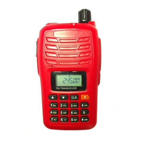
1: POWER SWITCH [POWER]/CONTROL DIAL [VOL]
Rotate to adjust the volume level, to turn the power ON and OFF.
2:CTCSS SWITCH
Push and hold to force the CTCSS open and set the transceiver
3:PTT SWITCH [PTT]
Push and hold to transmit; release to receive.
4:SQUELCH SWITCH [SQL]
Push and hold to force the squelch open and set the transceiver
to the squelch level adjustable condition.
5:UP/DOWN KEYS
Selects the operating frequency.[UP]/[DN]
6:KEY PAD
Used to enter operating frequency, the DTMF codes, etc.
7:ANTENNA CONNECTOR
Connects the supplied antenna.
8:[SP]/[MIC] JACK
Connect an optional speaker-microphone or headset, if desired.
The internal microphone and speaker will not function when either is connected.
9:FUNCTION DISPLAY
*The assigned function for [SQL] and [DP]/[DN] can be traded in INITIAL SET MODE.
9

10
BASIC OPERATION
Power ON
POWER SWITCH
Rotate to adjust the volume level, to turn the power ON and OFF.
Setting a frequency
UP/DOWN KEYS
Selects the operating frequency. [UP] / [DN]
Push [D•CLR] to select frequency mode
Push [C•MR] to select channel mode
Setting audio/squelch level
To set the audio level
Rotate [VOL] to set the desired audio level while receiving a signal.
To set the squelch level
While pushing [SQL], push [UP]/[DN] to set the squelch level.
•The squelch level “0” is loose squelch,“25” is tight squelch.
4
Receive and transmit
Adjust audio volume to the desired level.
Set a frequency.
When a signal is received:
• Squelch opens and audio is emitted from the speaker.
• Signal indicator shows the relative signal strength level.
Push [A•FUNC], then push [9•H/L] to toggle output power between high and low.
• “L” appears when low output power is selected.
Push and hold [PTT] to transmit, then speak into the microphone.
• “TX” appears.
•Do not hold the microphone too close to your mouth or speak too loudly. This may

distort the signal.
Release [PTT] to receive.
SUBAUDIBLE TONES
Tone squelch
Operation
The tone squelch opens only when receiving a signal containing a matching
subaudible tone. You can silently wait for calls from group members using the same
tone.
Set the operating frequency.
• Set the AF and squelch to the desired level as the normal operation.
Set the desired subaudible tone in the SET MODE.
While pushing [CSTCC], push [UP]/[DN] to set the CTCSS.
• “ ” appears when selecting CTCSS.
When the received signal includes a matching tone, squelch opens and the signal
can be heard.
•When the received signal’s tone does not match, tone squelch does not open
•To open the squelch manually, push and hold [SQL].
Operate the transceiver in the normal way.
FUNCTION
Push [A•FUNC], then push [2•VOX] to toggle VOX mode.
Push [A•FUNC], then push [3•T.SCAN] to toggle CTCSS SCAN mode.
Push [A•FUNC], then push [5•SCAN] to toggle SCAN mode.
11

12
B
b
o
O
c
1
2
n
4
5
Push [A•FUNC], then push [#•ENT] to toggle KEY LOCK mode.
Push [*•OPTION], VIEW battery voltage.
The new increase function illuminate of V5:
1:Change the channel from the keyboard directly
esides use the button up(△)、button down(▽)to change the channel,you can input the channel number
y keyboard directly too. e.g. change CH-12 into CH-68,press button B CALL first,the [ CH-_ _ ] will display
n the LCD, and then input 6、8 directly,press button ENT and it’s complete。
perate process:B →6 →8 →ENT
2:P1-P9 work frequency of channel deposited
For example, you want to deposited the receive frequency 245.100 and transmit frequency 245.200 into
hannel P8。
1:Choose the channel P8 to deposited frequency;
2:Press button A FUNC ,F will display on LCD;
3:Press button C MR , the [ R45.000 ] will display on LCD;
4:Press button up(△)、button down(▽)to change frequency,until the [ R45.100 ] display on LCD;
5:Press button C MR,there will sound “DU”,receive frequency 245.100 have save;
6:Press button D CLR again,the [ T45.100 ] will display on LCD;
7:Press button up(△)、button down(▽)to change frequency,until the [ T45.200 ] display on LCD;
8:Press button C MR,there will sound “DU”,transmit frequency 245.100 have save;
9:Press button A FUNC ,quit setting mode。
3:Examine work frequency of channel P1-P9(for example examine channel P8)
1:When on the channel P8;
2:Press button A FUNC ,F will display on LCD;
3:And then press button C MR, the [ R45.100 ] will display on LCD,and then display [ T45.200 ];
Five number figure DTMF call:
1:Set the ID number of machine
:Press button [A FUNC] ,Fwill display on LCD;
:Press button [0 DTMF-M] ,the [ d-***** ] will display on LCD,“ * ” represent figure 0~9,just as five ID
umber of the machine;
3:If now you want to change the ID number of the machine,when the [ d-***** ] display on the LCD, press
button [ ENT ],the [ d-_ _ _ _ _ ] will display on LCD;
:Input five figure directly,such as 1、2、3、4、5,if input mistake , you can press button “ * ” to input it again ;
:After input the numerical value is correct,press button ENT to save and quit.

13
1
2
3W
o
a
2:Function of call(for example call the machine which ID number is 56789)
:Press button [0 DTMF-M ],the [ d t _ _ _ _ _ ] will display on LCD;
:Input five figure directly ,5、6、7、8、9,if input mistake can press button “ * ” to input it again;
:After numerical value input is correct,can press button [ ENT ] to transmit to quit.
hen the machine which ID number is 56789 receive the call,Caller’s ID number [ dc12345 ] will display
n LCD,the machine which ID number is 12345 call him,at same time the hom will sound ten times,press
ny key to stop the ring.
Charge:
Improve the charger,in order to attain the request of you,we have spend much time on renewedly
experimention and design the circuit of charger. Adjust indictor light as that, when the stand-by is yellow light;
when the charge is red light; when abound is green light.(charge current 500mA),as bellow:
The colour of
indictor light yellow red green green
The time of
charge(hour) Stand-by mode 0~3h 3h~5h 3h~5h
Charge current Stand-by mode 500mA 120mA 120mA
Charge degree of
battery Stand-by mode 0~80% 80%~100% abound
Other manuals for V5
1
Table of contents
Other Benison Transceiver manuals
Popular Transceiver manuals by other brands
TTI
TTI Freequency TCB-770 instruction manual
Kenwood
Kenwood TH-25A Series instruction manual
Technisonic Industries Limited
Technisonic Industries Limited TDFM-9300 operating instructions

General Radiotelephone Company
General Radiotelephone Company Super MC-IIA Operation guide

Alinco
Alinco DR-138 instruction manual
swiftech
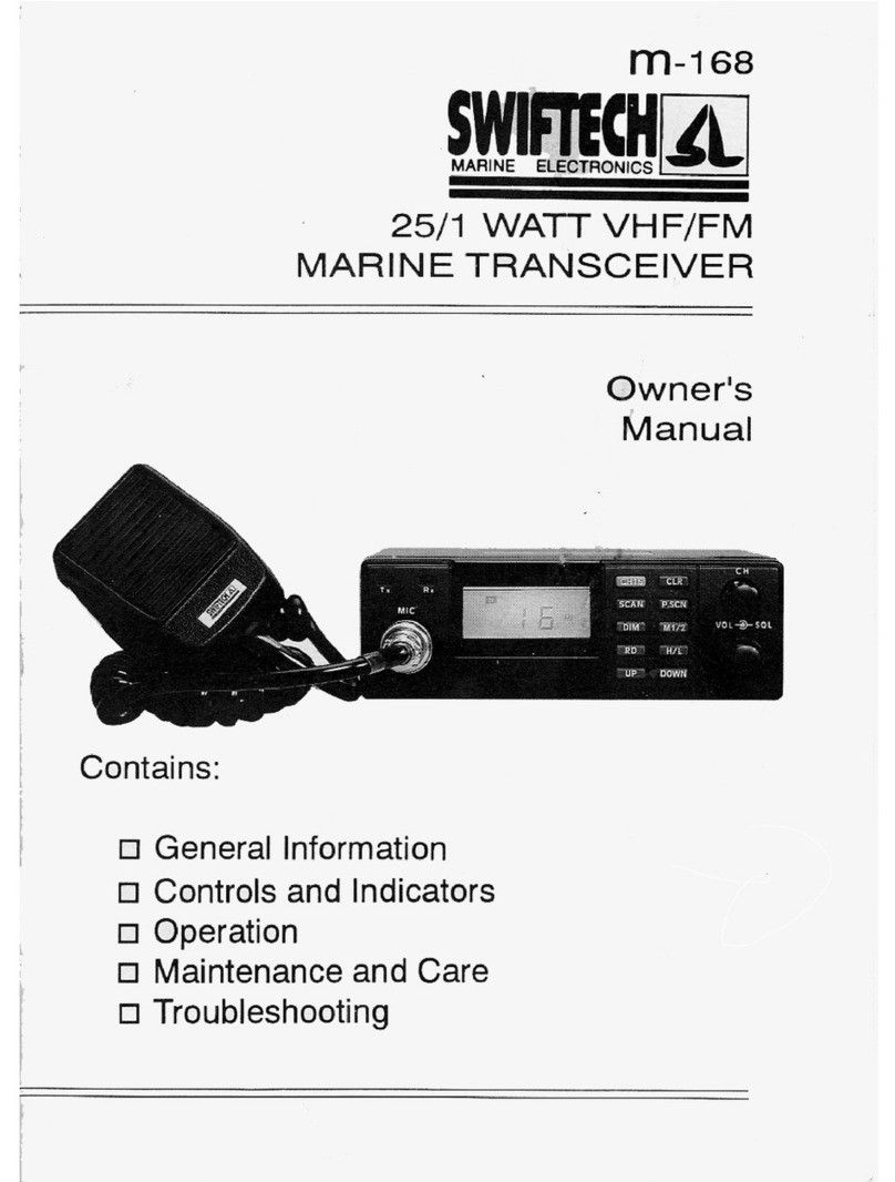
swiftech m-168 owner's manual
