BenQ DV M21 User manual

BENQ
DVM21
servicemanual
Preliminaryversion
2009/12/11
Content
1.Aboutthismanual.....................................................................................2
2.Safetyprecaution......................................................................................2
3.Thefirmwareupdateprocedure...............................................................2
4.DisassemblyProcedure.............................................................................6
5.TheTroubleshootingguide.....................................................................17
6.TheBillofMaterial..................................................................................22
7.Schematicsdiagram................................................................................40

2
1. Aboutthismanual
Thisservicemanualcontainsinformationformaintenanceand
serviceofDVM21;highdefinitioncamcorder.Themanualmight
guide&helpyoutodothesystemdiagnostics,Firm/Wareupdate
andtheproducttroubleshooting.
2. Safetyprecaution
2.1 ThisproductcontainsHighVoltagecircuitmighthurtsservice
peoplewhomwithoutelectronicknowledgeorinadequate
training.
2.2 WarningtoaCardiac,foryourhealthy&avoiddangeroushigh
voltageelectricshock,westronglysuggestyoudonottryto
opening&servicingthisproduct.
2.3 BesuretodischargetheHighVoltagestorageenergypriorto
disassemblytheenclosure.
i.e.removeentirelypowersources(Li‐ionbattery,AAbattery&
USBport)&wait30minutesforcircuitryselfdischarge.
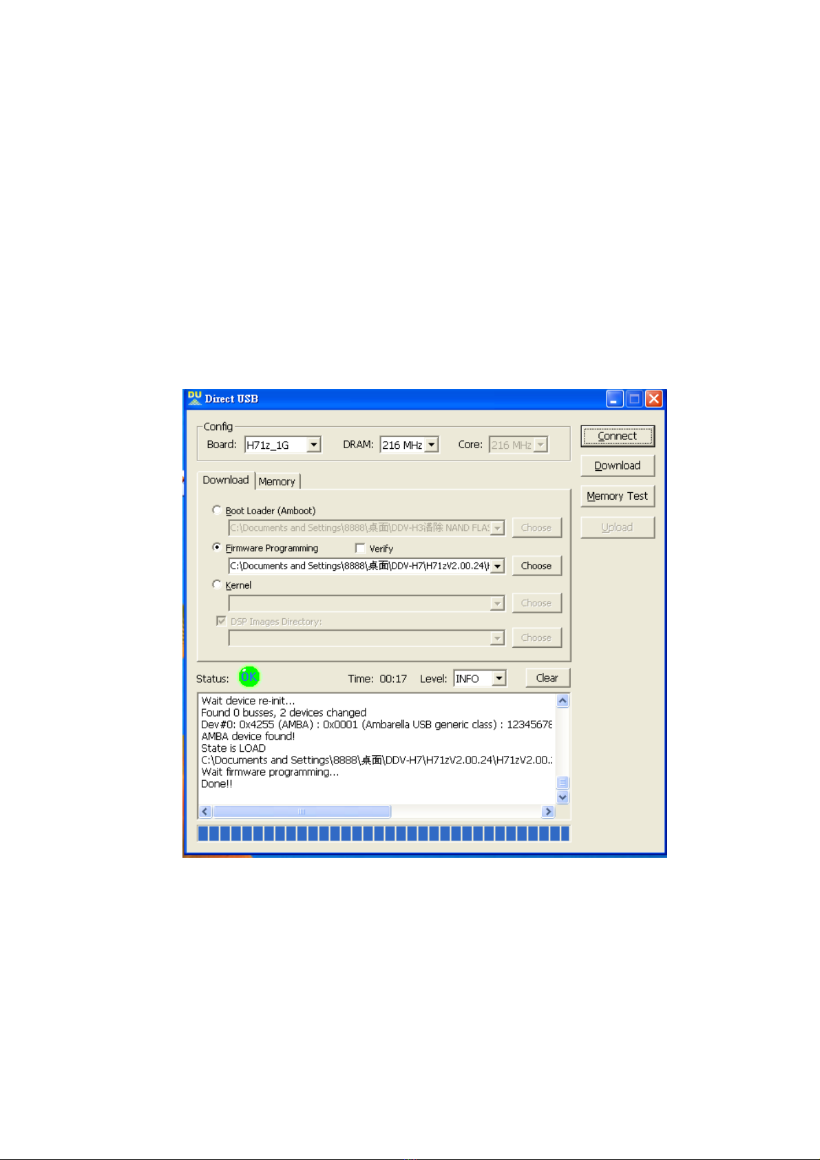
3. Thefirmwareupdateprocedure
3.1 Installtheupdatetool,(“DU,DirectUSB”)inyourcomputer.
3.2. Launch“DU”utility,thenthedialogueboxwillappearas
below.

3
3.3. ConnecttheUSBcablebetweenPC&Camcorder.
3.4. Configuretheproduct;selectyourmainboardconfiguration&
DRAMspeedthatmeetsyourcamcorderspecification.
3.5. Therearetwosourcepaths;oneisforentirelyerasingtheflash
memory,andanotheroneisforquickupdatepurpose
respectively.
3.6. The“BootLoader”pathisforentirelyerasingtheflashmemory
whenfataldesignchanges.
3.7. Usingthe“BootLoader”pulldownmenutobrowsethelocation
ofspecialerasing/replacementfirmwareprovidedbytheDSP
supplier;named“amboot_kernel_fomfs_dsp_release.elf.bin”.
4
3.8. Usingthe“Firmwareprogramming”pulldownmenutobrowse
thelocationofnewfirmwaretobeupdated,e.g.C:\Documents
andsetting\Myfile\Programmingcodes\
amboot_xx_xxx_dsp_releasexx.elf
3.9. Forquickupdate;select“Firmwareprogramming”optioncheck
&press“Connectbutton”toconnectcamcorderandthenpress
“Download”buttontoupdatenewfirmware.
3.10. Forfataldesignchangewillerasetheoldfirmwareresidentin
thecamcorderfirst,otherwisethecamcordermightwork
improperly.

5
3.11. Select“BootLoader”optioncheck&press“Connectbutton”
toconnectcamcorderandthenpress“Download”buttonto
entirelyerasingtheflashmemory.
3.12. Andthenexecutionstep3.9quickupdateFirmware,thenyour
camcorderhasbeencompleteupdated.

6
4. DisassemblyProcedure
4.1. Toolused:
Atweezers,ascrewwrench,amagnetic,anantiESDsponge,an
ESDdischargingwriststripandasolderiron.
4.2. BesuretofullydischargetheHighvoltageenergypriorto
disassembletheunit,refertoSafetyprecautionsection2.2
~2.4.
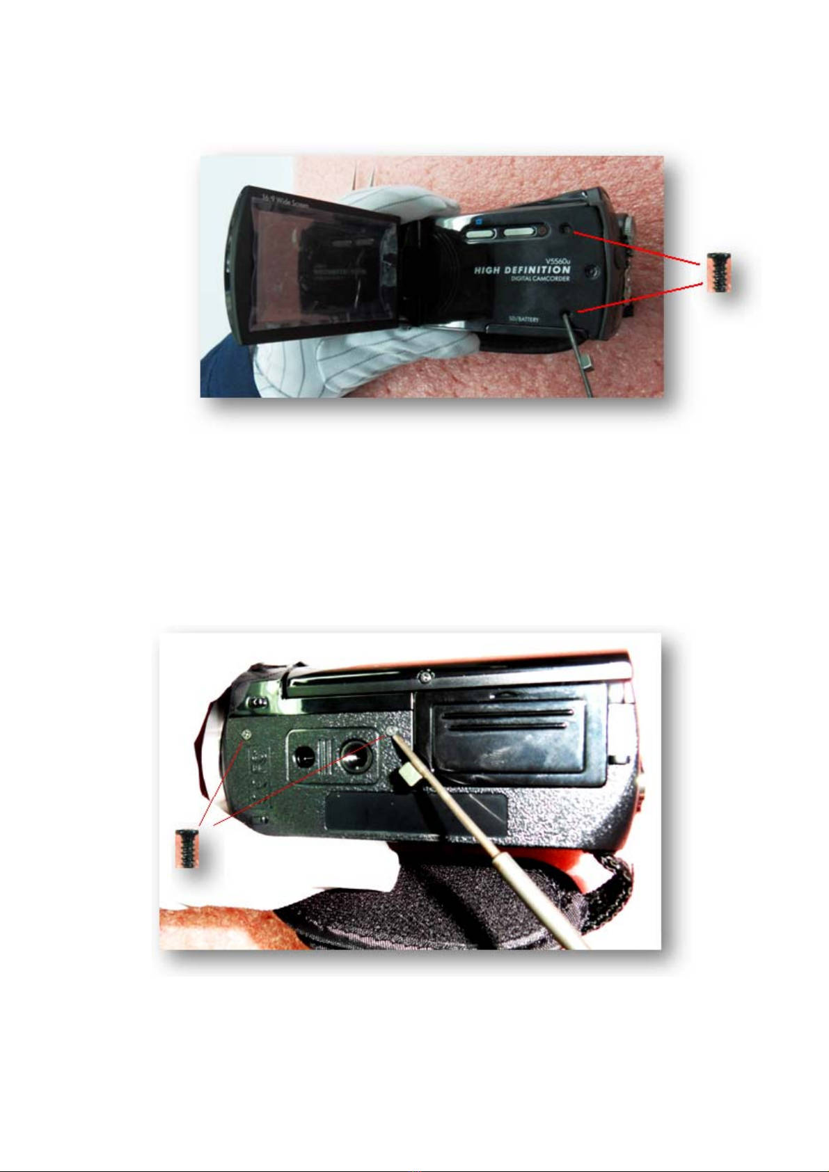
4.3. Stickingasmallmagnetonthewrenchtipasphotoshown
belowforeasyhandlingthesetinyscrews.
7
4.4. Releasebothscrewsasphotoshownbelow:
Note:(0.7kgf‐cm)torquescontrolisessentiallyforre‐assembly
otherwiseovertorquemightpermanentdamagetoyour
camcorder.
4.5. Then,releasebottomsidescrews:

8
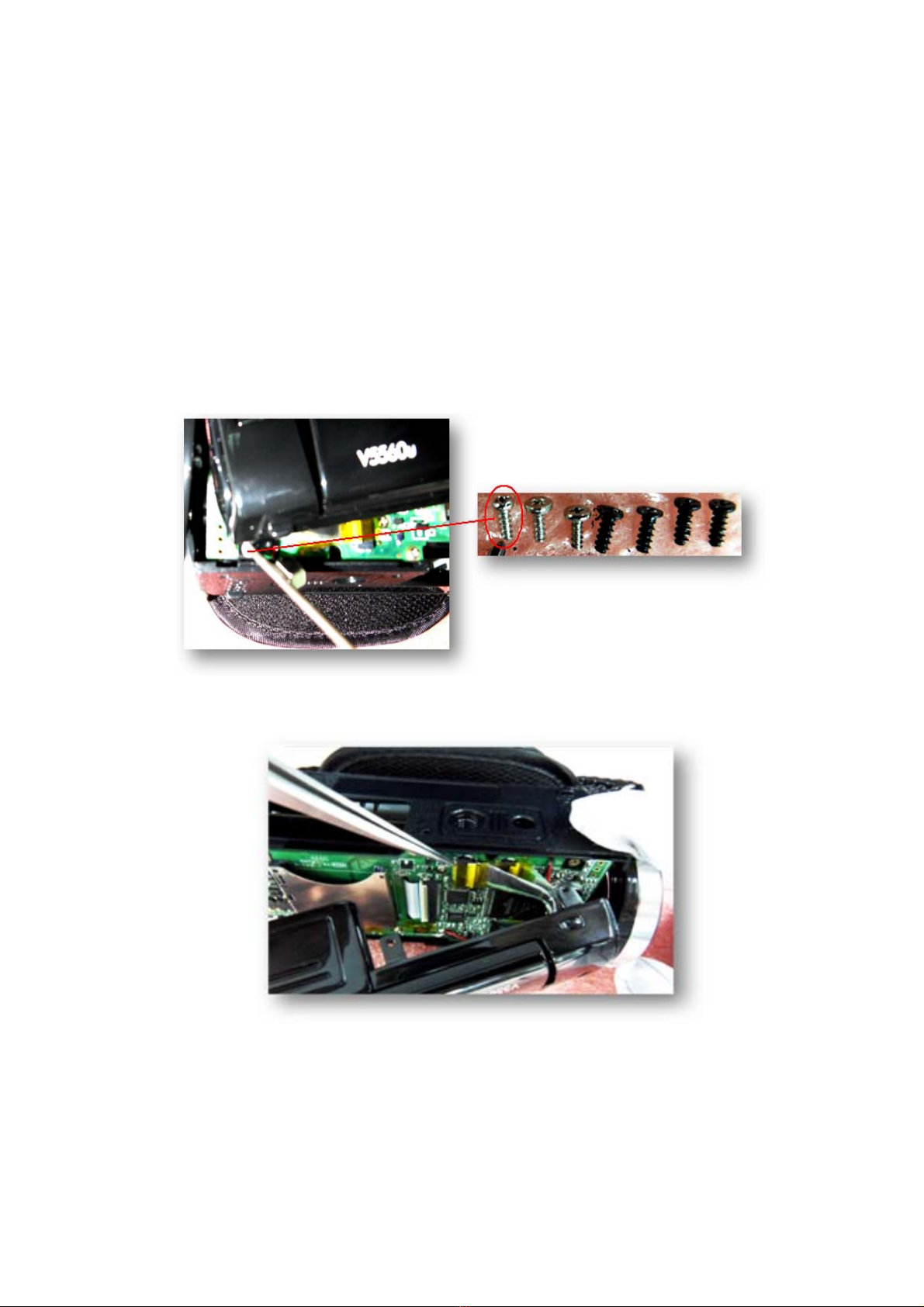
4.6. Then,releasebothIOboard’sscrewsundertherubbercover
4.7. Pull&partiallyopenthefrontendoftheLCDmodulecarefully.

9
4.8. PartiallyopentherearendoftheLCDmoduleverycarefully,
otherwisetheflatcables,FPCB,connectbetweenLCM&main
boardwillbedestroyed.
Note:That’salittletoughtodisassembletheLCDmodule;
coursedof4ribs/hooksclampinner.Pleasebepatientandtake
yourtime.
10
4.9. Releasetheedgescrewverycarefully,don’tdamegetheFPCB,
FlatCable.
ImportantNote:That’saspecialdesign;narrowheadscrew
dedecateforhere,limitspace;wrongtypeofscrewusedmight
causedFPCBcabledemage.
4.10. Peelofftheyellowtapesusingthetweezers.
4.11. UnlocktheFPCBconnector’slatch&releasetheFPCBcables.
Table of contents
Other BenQ Camcorder manuals


Popular Camcorder manuals by other brands


Panasonic
Panasonic AG-HMC152EN operating instructions

Insignia
Insignia NS-DCC5HB09 - Camcorder - 720p user guide

MYDLINK
MYDLINK DCS-6100LH Quick installation guide

Sony
Sony video Hi8 Handycam CCD-TR555 operating instructions

SECURECOM
SECURECOM V-5014B installation guide

Panasonic
Panasonic HDC-SD100 operating instructions


