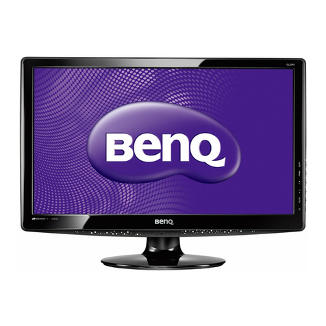
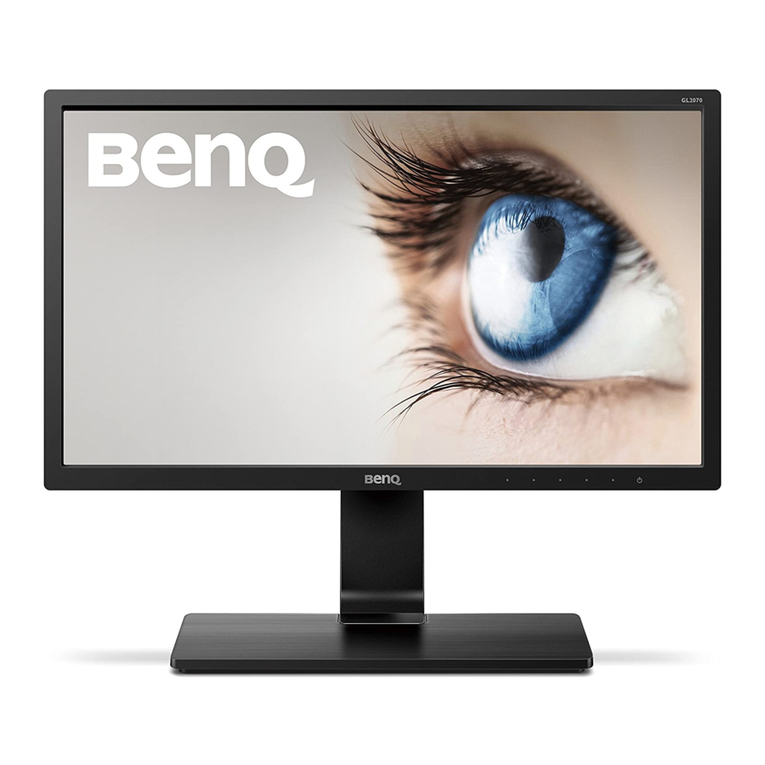
BenQ G2010WP User manual

1
Product Service Manual--Level 2
Service Manual for BenQ:
G2010W
P/N: 9H.0CALN.IXX
Applicable forAll Regions
Version: 001
Date:2008/5/8
Notice:
- For RO to input specific “Legal Requirement” in specific NS regarding to responsibility and liabilit
y
statements.
- Please check BenQ’s eSupport web site,http://esupport.benq.com,to ensure that you have the most
recent version of this manual.
First Edition (June,2006)
© Copyright BenQ Corporation 2006.All Right Reserved.

2
Content Index
Abbreviations & Acronyms ..................................................................................................3
1. About this manual.............................................................................................................3
1.1 Trademark ........................................................................................................................... 3
2. Precautions & Safety Notices...........................................................................................4
2.1 Safety Precaution.................................................................................................................. 4
2.2 Product Safety Notice............................................................................................................ 4
2.3 Service Notes........................................................................................................................ 4
3. Product Overview..............................................................................................................5
3.1 Power Supply ....................................................................................................................... 5
3.2 Signal Interface..................................................................................................................... 5
3.3Video Performance ............................................................................................................... 6
3.4 Scan Range........................................................................................................................... 6
3.5 Plug & Play DDC2B DDC-CI Support .................................................................................... 7
3.6 Support Timings................................................................................................................... 8
3.7 Operational & Function Specification................................................................................... 11
3.8.LCD Characteristics ........................................................................................................... 13
3.9 User Controls..................................................................................................................... 14
3.10 Mechanical Characteristics................................................................................................. 14
3.11 Pallet & Shipment ............................................................................................................. 15
4 Level 1 Cosmetic / Appearance / Alignment Service.....................................................17
4.1 Software / Firmware Upgrade Process ................................................................................... 17
4.2 Alignment Procedure (for function adjustment)..................................................................... 17
5. Level 2 Disassembly/Assembly/Circuit Board/Standard Parts Replacement ............22
5.1 Exploded Diagram.............................................................................................................. 22
5.2 Assembly Block................................................................................................................... 24
5.3 Disassembly Block .............................................................................................................. 26
5.4 Block Diagram ................................................................................................................... 29
5.5 Circuit Operation Theory.................................................................................................... 32
5.6 Trouble Shooting Guide....................................................................................................... 35
3
Abbreviations & Acronyms
1. About this manual
This manual contains information about maintenance and service of BenQ products.Use this
manual to perform diagnostics tests,troubleshoot problems,and align the BenQ product.
1.1 Trademark
The following terms are trademarks of BenQ Corporation:
BenQ
Importance
Only trained service personnel who are familiar with this BenQ Product shall perform service or
maintenance to it.Before performing any maintenance orservice,the engineer MUST read the
“Safety Note”

4
2. Precautions & Safety Notices
2.1 Safety Precaution
This monitor is manufactured and tested on a ground principle that a user’s safety comes first.However, improper used
or installation may cause damage to the monitor as well as to the user.
WARNINGS:
zThis monitor should be operated only at the correct power sources indicated on the label on the rear of the monitor.
If you’re unsure of the power supply in you residence,consult your local dealer or Power Company.
zDo not try to repair the monitor by yourself, as it contains no user-serviceable parts.This monitor should only be
repaired by a qualified technician.
zDo not remove the monitor cabinet.There is high-voltage parts inside that may cause electric shock to human
bodies.
zStop using the monitor if the cabinet is damaged.Have it checked by a service technician.
zPut your monitor only in a lean, cool,dry environment.If it gets wet,unplug the power cable immediately and
consult your closed dealer.
zAlways unplug the monitor before cleaning it. Clean the cabinet with a clean, dry cloth.Apply non-ammonia based
cleaner onto the cloth,not directly onto the class screen.
zDo not place heavy objects on the monitor or power cord.
2.2 Product Safety Notice
Many electrical and mechanical parts in this chassis have special safety visual inspections and the protection
afforded by them cannot necessarily be obtained by using replacement components rated for higher voltage,wattage,
etc.Before replacing any of these components read the parts list in this manual carefully. The use of substitute
replacement parts, which do not have the same safety characteristics as specified in the parts list, may create shock,
fire,or other hazards.
2.3 Service Notes
zWhen replacing parts or circuit boards,clamp the lead wires around terminals before soldering.
zKeep wires away from high voltage,high temperature components and sharp edges.
zKeep wires in their original position so as to reduce interference.
zAdjustment of this product please refers to the user’manual.

5
3. Product Overview
3.1 Power Supply
Item condition Spec OK NA Remark
InputVoltage range Universal
input full
range
100~240VAC √
Input Current range 100Vac
240Vac 1.5A (max.)
0.7A (max.) √
Power consumption without Audio,
normal“on”
operation
≤55W √LED: Green
DMPS <2W
√LED: Orange
In rush Current 100Vac,cold
star,25°C;
240Vac,cold
star,25°C
40A (max)
60A(max)
√To be
determined by
the business
country.
Earth Leakage Current
Hi-pot
Power Line Transient
CCFL Operation range
Power cord √
3.2 Signal Interface
VGA:
Pin Symbol Pin Symbol Pin Symbol
1 Red+ 6 Red_GND 11 GND
2 Green+ 7 Green_GND 12 DDC_DAT
3 Blue+ 8 Blue_GND 13 Hsync
4 NC 9 5V_VGA 14 Vsync

6
5 Cable Detect 10 GND 15 DDC_CLK
DVI:
1 2 3 4 5 6 7 8
TMDS 數據
2- TMDS 數據 2+ TMDS 數據
2/4 屏蔽 TMDS 數據 4- TMDS 數據
4+ DCC 時鐘 DCC 數據
模擬垂直
同步
9 10 11 12 13 14 15 16
TMDS 數據
1- TMDS 數據 1+ TMDS 數據
1/3 屏蔽 TMDS 數據 3- TMDS 數據
3+ +5V 電源 接地(+5V,
模擬 H/V
Sync)
Hot Plug
Detect
17 18 19 20 21 22 23 24
TMDS 數據
0- TMDS 數據 0+ TMDS 數據
0/5 屏蔽 TMDS 數據 5- TMDS 數據
5+
TMDS 時
鐘屏蔽
TMDS 時
鐘+
TMDS 時
鐘-
3.3Video Performance
Item condition Spec OK NA Remark
Max.support Pixel rate 165MHz √
Max.Resolution 1680×1050 √
Rise time+Fall time <25% of
minimum pixel
clock period
√Refer to VESA
VSIS Standard
V1R2
Setting Time after
overshoot/undershoot
<5% final
full-scale value
√Refer to VESA
VSIS Standard
V1R2
Overshot/undershoot <12% of step
function voltage
level over the full
voltage range
√Refer to VESA
VSIS Standard
V1R2
3.4 Scan Range
Item condition Spec OK NA Remark
Horizontal
Sync polarity: (+) or (-)
31 ~83KHz
√

7
Vertical
Sync polarity: (+) or (-) 55~76Hz
√
3.5 Plug & Play DDC2B DDC-CI Support
Item condition Spec OK NA Remark
DDC channel type DDC 2B √
EDID Version 1.3
√

8
3.6 Support Timings
Preset Pixel
Format
Horz Freq
(kHz)
Horz
Polarity
Vert Freq
(Hz)
Vert Polarity
Pixel Clk
(MHz)
1 640 x 350 31.47 + 70.09 - 25.18 Preset
2 640 x 350 37.86 + 85.08 - 31.50 Fail safe mode
3 640 x 400 31.47 - 70.09 + 25.18 Non preset
4 640 x 400 37.86 - 85.08 + 31.5 Fail safe mode
5 640 x 480 35.00 - 66.67 - 30.24 Non preset
6 640 x 480 31.47 - 59.94 - 25.17 Preset
7 640 x 480 37.86 - 72.81 - 31.50 Non preset
8 640 x 480 37.50 - 75.00 - 31.50 Preset
9 640 x 480 43.27 - 85.01 - 36.00 fail safe mode
10 720 x 400 31.47 - 70.08 + 28.32 Preset
11 720 x400 37.93 - 85.04 + 35.5 fail safe mode
12 832 x 624 49.71 - 74.53 - 57.27 Preset
13 800 x 600 35.16 + 56.25 + 36.00 Non preset
14 800 x 600 37.88 + 60.32 + 40.00 Preset
15 800 x 600 48.08 + 72.19 + 50.00 Non preset
16 800 x 600 46.88 + 75.00 + 49.50 Preset
17 800 x 600 53.67 + 85.00 + 56.25 fail safe mode
18 848 x 480 31.02 + 60.00 + 33.75 Non preset
19 848 x 480 29.83 - 59.66 + 31.50 Non preset
20 848 x 480 35.00 - 70.00 + 37.52 Non preset
21 848 x 480 36.07 - 72.00 + 39.25 Non preset
22 848 x 480 37.68 - 74.77 + 41.00 Non preset
23 720 x 576 35.83 - 60.00 - 32.71 Non preset
24 1024 x
768-I 35.52 + 43.38 + 44.9 Out of range
mode
25 1024 x 768
48.36 - 60.00 - 65.00 Preset
26 1024 x 768
56.48 - 70.07 - 75.00 Non preset
27 1024 x 768
57.67 - 72.00 + 78.43 Non preset
28 1024 x 768
60.24 - 74.93 - 80.00 Preset
29 1024 x 768
60.02 + 75.03 + 78.75 Preset
30 1024 x 768
68.68 + 85.00 + 94.50 fail safe mode
31 1152 x 720
44.86 - 60 + 66.75 Preset
32 1152 x 864
63.85 + 70.01 + 94.50 Non preset

9
Preset Pixel
Format
Horz Freq
(kHz)
Horz
Polarity
Vert Freq
(Hz)
Vert Polarity
Pixel Clk
(MHz)
33 1152 x 864
67.50 + 75.00 + 108.00 Non preset
34 1152 x 864
77.09 + 85.00 + 121.50 fail safe mode
35 1152 x 870
68.68 - 75.06 - 100.00 Preset
36 1152 x 900
61.80 - 65.95 - 92.94 Preset
37 1152 x 900
71.73 - 76.07 - 105.59 Non preset
38 1280 x 720
45.00 - 59.94 + 74.25 Non preset
39 1280 x 720
44.77 - 59.86 + 74.50 Non preset
40 1280 x 720
56.46 - 74.78 + 95.75 Non preset
41 1280 x
768-R
47.40 + 60.00 - 68.25 Preset
42 1280 x 768
47.78 - 59.87 + 79.50 Non preset
43 1280 x 768
60.29 - 74.89 + 102.25 Non preset
44 1280 x 768
68.63 - 84.84 + 117.50 fail safe mode
45 1280 x 800
61.648 + 59.81 - 83.50 Preset
46 1280 x 800
62.8 - 75 + 106.5 Preset
47 1280 x 960
60.00 + 60.00 + 108.00 Preset
48 1280 x 960
85.94 + 85.00 + 148.50 fail safe mode
49 1280 x
1024
63.98 + 60.02 + 108.00 Preset
50 1280 x
1024
74.88 + 69.85 + 126.99 Non preset
51 1280 x
1024
74.40 - 70.00 - 124.90 Non preset
52 1280 x
1024
77.90 + 72.00 + 134.60 Non preset
53 1280 x
1024
79.98 + 75.02 + 135.00 Preset
54 1280 x
1024
81.18 - 76.16 - 135.09 Non preset
55 1280 x
1024
91.15 + 85.02 + 157.50 fail safe mode
56 1360 x 768
47.71 + 60.01 + 85.50 Preset
57 1400 x
1050-R
64.74 + 59.95 - 101.00 Non preset

10
Preset Pixel
Format
Horz Freq
(kHz)
Horz
Polarity
Vert Freq
(Hz)
Vert Polarity
Pixel Clk
(MHz)
58 1400 x
1050
65.32 - 59.98 + 121.75 Non preset
59 1400 x
1050
82.28 - 74.87 + 179.50 Non preset
60 1400 x
1050
93.88 - 84.96 + 179.50 Non preset
61 1440 x
900-R
55.496 + 59.901 - 88.75 Preset
62 1440 x 900
55.935 - 59.887 + 106.5 Preset
63 1440 x 900
70.6 - 75 + 136.75 Preset
64 1600 x
1200-R
74.01 + 59.92 - 130.25 fail safe mode
65 1600 x
1000-R
61.648 + 59.910 - 108.5 fail safe mode
66 1600 x
1200
75.00 + 60.00 + 162.00 fail safe mode
67 1600 x
1200
81.25 + 65.00 + 175.50 fail safe mode
68 1600 x
1200
87.50 + 70.00 + 189.00 fail safe mode
69 1600 x
1200
93.75 + 75.00 + 202.50 fail safe mode
70 1600 x
1200
106.25 + 85.00 + 229.50 Out of range
mode
71 1680 x
1050-R
64.67 + 59.88 - 119.00 Preset
72 1680 x
1050
65.29 - 59.95 + 146.25 Preset
73. 1680 x
1050
75 - 82.3 + 187 Preset
74 1972 x
1344
83.64 - 60.00 + 204.75 fail safe mode
75 1972 x
1344
106.27 - 75.00 + 261.00 Out of range
mode
76 1856 x 86.33 - 60.00 + 218.25 Out of range

11
Preset Pixel
Format
Horz Freq
(kHz)
Horz
Polarity
Vert Freq
(Hz)
Vert Polarity
Pixel Clk
(MHz)
1392 mode
77 1856 x
1392
112.50 - 75.00 + 288.00 Out of range
mode
78 1920 x
1080-R
66.587 + 59.934 - 138.5 fail safe mode
79 1920 x
1080
67.158 - 59.963 + 173 fail safe mode
80 1920 x
1200-R
74.04 + 59.95 - 154.00 fail safe mode
81 1920 X
1200
74.56 - 59.89 + 193.25 fail safe mode
82 1920 X
1200
94.04 - 74.93 + 245.25 Out of range
mode
83 1920 X
1200
107.18 - 84.93 + 281.25 Out of range
mode
84 1920 X
1440
90.00 - 60.00 + 234.00 Out of range
mode
85 1920
X1440
112.50 - 75.00 + 297.00 Out of range
mode
3.7 Operational & Function Specification
3.7.1Video Performance
* All Spec.of monitor need to warm up at lease 1hr
Item condition Spec OK NA Remark
Resolution Any input resolution
modes which are list in
the timing table (under
1680x1050).
Max.
resolution
1680x1050
Contrast ratio 1000:1
Brightness 300 cd/m2
(Typ.)
Response time 5ms(typ.)
80Viewing angle
80

12
CIE coordinate of white x--0.313 ±
0.020;
y--0.329 ±
0.020
Display colors 16.7M
(6bit+Hi-FR
C)
3.7.2 Brightness Adjustable Range
Item condition Spec OK NA Remark
Brightness adjustable range At default
contrast level
(saturate
point)&
Full-white
color pattern
≧240 cd/m2
(Setting
brightness max.
value 100%; Min.
brightness value)
√
3.7.3 Acoustical Noise
Item condition Spec OK NA Remark
Acoustical Noise At 1 meter
distance&
audio function
disable
√
3.7.4 Environment
3.7.5 Transportation
Item condition Spec OK NA Remark
Vibration
Item condition Spec OK NA Remark
Operating 0°C to 40°C √Temperature
Non-operating -20°C to 60°C √
Operating 20% to 90% √Humidity
Non-operating 10% to 90% √
Operating 0 to 3048 M (10000 ft) √Altitude
Non-operating 0 to 12192M (40000 ft) √

13
Unpackage
vibration
Drop
shock
3.7.6 Electrostatic discharge Requirements
Item condition Spec OK NA Remark
Electrostatic discharge
3.7.7 Reliability
Note.Display an all WHITE field at mid Brightness and Contrast settings
3.7.8 Audio performance
Items Specification
Speaker
Input impedance
Frequency response range
Signal to noise ratio
Output power
3.8.LCD Characteristics
3.8.1 The physical definition &technology summary of LCD panel
Item condition Spec OK NA Remark
LCD panel supplier AUO
Panel type of supplier M201EW02
Screen diagonal 20.1 inch diagonal
Display area 433.44(H)x270.90(V) mm
Pixel pitch 0.258(H) x 0.258(V)
Pixel arrangement RGB vertical stripe
Display mode Normally White
Support color 16.7M (6bit+Hi-FRC)
Items Condition Spec Note
MTBF 90% Confidence ≧60,000 Hours
CCFL Life time Luminance becomes 50% 50000(Min)Hours

14
3.9 User Controls
User’s hardware control definition:
CONTROL KEY
KEYS FUNCTION
[MENU]
A. When OSD displays, press [MENU] to return to previous level menu
B. When OSD isn’t shown on screen,press [MENU] to enter OSD interface
C. Press [MENU] to enter Service PageWhen OSD isn’t shown on screen in Service Page
Mode
[Enter]
A. When OSD displays, press [Enter] to perform function of menu icon that is highlight or
enter next level menu
B When OSD isn’t shown on screen, press[Enter] to change input source
[],[]
A.When“MENU OSD”displays,press these keys to change the contents of an adjustment item,
or change an adjustment value
B.When“MENU OSD”un-displays, press [] to Show Picture Mode Menu.press [] to show
Brightness/Contrast Menu
[POWER] Power on or power off the monitor
[iKey] press [iKey] to perform auto-adjustment
3.10 Mechanical Characteristics
3.10.1Dimension
Item condition Spec OK NA Remark
Bezel opening Lx W 435.73x273.19mm √
Monitor without stand L×W×Hmm 472.54x166.66x383.67mm √
Monitor with stand L×W×Hmm 472.73x62.2x373.35mm √
Carton Box(outside) L×W×Hmm 538x134x446mm √
Tilt and Swivel range Tilt:-5~21degree
Swivel: 0 degree
√
3.10.2Weight
Item condition
Spec OK
NA
Remark
Monitor (Net) 4.07±0.0.5 Kg ( Net ) √
Monitor with packing(Gross) 5.12±0.5Kg( Gross / with packing )
√
3.10.3 Plastic
Item condition Spec OK NA Remark
Flammability 94-HB √
Heat deflection to ABS 80°C √
UV stability ABS Delta E<12 √
resin ABS
√

15
Texture MT11000&MT11010&
MT11020& &
polishing2000&
polishing3000&
polishing5000&
polishing6000
Special Texture
√1.BEZEL: MT11000
& polishing5000&
polishing2000
2.BACK COVER:
MT11000 &
MT11020&
polishing2000
3.STAND:
MT11010&
polishing2000
4.POWER KEY
BUTTON:
polishing2000
5.LED: polishing6000
Others:MT11010
Color BCS-7015A(BLACK)/B
CS-T8110C(SILVER)
√
Bezel painting
3.10.4 Carton
3.11 Pallet & Shipment
3.11.1 Container Specification
Stowing Type Containter Quantity of Produces
(sets)
(Every container)
Quantity of Produces
(sets)
(Every Pallet)
Quantity of Pallet
(sets)
(Every container)
20’
780 Pallet A:92
Pallet B:64
Pallet C:--
Pallet A:5
Pallet B:5
Pallet C:--
40’ 1716 Pallet A:92
Pallet B:64
Pallet C:--
Pallet A:11
Pallet B:11
Pallet C:--
With Pallet
Carton:Item condition Spec OK NA Remark
Color Kraft
√
Material C Flute
√
Compression strength 200 KGF
√
Burst strrngth 16 KGF/cm2
√
Stacked quantity 6 Layers
√

16
20’ N/A N/A N/A
40’ N/A N/A N/A
Without Pallet
3.11.2 Carton Specification
Product:
NetWeight (Kg) Gross Weight(Kg) Dimension w/o Base
LxWxH (mm)
Dimension w/ Base
LxWxH (mm)
4.07±0.5 Kg ( Net) 5.12±0.5Kg 472.54X62.2X373.5mm 472.54X166.66X383.67mm
Package:
Carton Interior Dimension (mm)
LxWxH
Carton External Dimension (mm)
LxWxH
528X124X428mm
538X134X446mm

17
4 Level 1 Cosmetic / Appearance / Alignment Service
4.1 Software / Firmware Upgrade Process
Upload firmware to MCU viaVGA Cable
1.Connect ISP board between monitor and PC as below configuration.
2.Press the“connect”button in ISP.exe,and select the device type, which is used in this monitor.Choose the
corresponding firmware version,and load to MCU.
3.After finish, please plug out power cable and re-start monitor again.
4.2Alignment Procedure (for function adjustment)
4.2.1 Preparation:
1. Setup input timing VESA to 1680*1050@60Hz,32-Grays pattern.
2. Setup units and keep it warm up for at least 30 minutes.
4.2.2 Timing adjustment
1. Enter to factory mode setting area (by pressing “ENTER”+ “MENU” + “POWER” at the same time during power off).
2. Check the settings to following values:
Contrast =50;
Brightness=90;
Color enhancement=general;
3. Then turn off the monitor power.
4.2.3 Function key Definitions
4.2.3.1 Control buttons on the Back bezel
•“MENU”
When OSD displays, press [MENU] to return to previous level menuView the next
function in the OSD Main menu
When OSD isn’t shown on screen,press [MENU] to enter OSD interface
Press [MENU] to enter Service PageWhen OSD isn’t shown on screen in Service Page
Mode
•“ENTER”
Insert to Parallel
Port on PC
ISP Board
LCD Monitor
D-Sub
Parallel
Port
D-SUB

18
When OSD displays, press [Enter] to perform function of menu icon that is highlight
or enter next level menuActivate the OSD Main menu
When OSD isn’t shown on screen,press[Enter] to change input source
•“[],[]”
When“MENU OSD”displays,press these keys to change the contents of an
adjustment item,or change an adjustment value View the previous function in the
OSD Main menu
When“MENU OSD”un-displays,press [] to Show Picture Mode Menu.press [] to
show Brightness/Contrast Menu
•“iKey”
press [iKey] to perform auto-adjustment
•“POWER”
Turn on/off the monitor
4.2.3.2 OSD Control
The On-Screen Display (OSD) shall be an easy to use icon based menu through keypad OSD buttons or remote control
unit.The unit shall leave the factory with all OSD controls set to their default values
First level Second level Third level Fourth level Default
AutoAdjustment - - -
H.Position (0~100) - 50
V. Position (0~100) - 50
Pixel Clock (0~100) - 50
DISPLAY
Phase (0~63) - -
Brightness (0~100) - 90
Contrast (0~100) - 50
Sharpness (1~5) - 3
Normal Normal
Bluish -
Reddish -
*Color temperature
User Mode
¾Red (0~100)
¾Green (0~100)
¾Blue (0~100)
100
Color
Reset Color (YES/NO)
PICTURE
Dynamic Contrast *Dynamic Contrast
(YES/NO)
Standard Standard
Movie Sharpness 不可调节
PICTURE
ADVANCED
**Picture Mode
Dynamics Sharpness 不可调节
1.任一项模式下
Senseye Demo 设为
ON 另外两个模式

19
Photo Sharpness 不可调节
下的 Senseye Demo
自动变为 ON
2.Senseye Demo 处
于ON 时,做Auto
自动变为 OFF
sRGB Sharpness 不可调节
Senseye Demo (ON/OFF) OFF
Full full
Display Mode Aspect
Input (D-sub/DVI)
Language
-EU version: 14 languages
(English/Français/Deutsch/Italiano/Espanol/Po
lish/Czech/Hungarian/Serbo-croatian/Romani
an/Netherlands/Russian/Swedish/Protuguese)
-Asian version: 8 languages
(English/Francais/Deutsch/Italiano/Espanol/日
本語/繁體
中文/简体中文)
English
H.Position (0~100) 50
V.Position (0~100) 50
Display Time (5,10, 15,20, 25,30) 15
OSD Settings
OSD Lock (ON/OFF)(按 Menu 鍵15s 即可解除鎖定)
OFF
DDC/CI (ON/OFF) - ON
Information - -
SYSTEM
Reset All (YES/NO) -
4.2.3.3.Factory Mode Introduction
When signal is input, press “power key”to turn off the monitor. Press “ENTER”+“MENU”+“Power” together to
turn on the monitor. After power on, press “MENU”to call out Main Menu, then press “-“for select the “F”item, then
press“Enter”,you can go into Factory mode.
AUTO: Automatically calibrate chip ADC parameter by using chip internal DAC.
GAIN: ADC gain value
OFFSET: ADC offset value
9300K: Set color temperature 9300K
5800K: Set color temperature 5800K
6500K: Set color temperature 6500K
USER: Setuserpreferredcolortemperature
LANGUAGE: Country language
Reset BL Hr: the time of backlight
Reset Total Hr: the total time when connect power
Return:exit the factory menu
4.2.3.4 After repair, to ensure the quality you should do the following test and adjustment

20
Item Content Equipment
Test OSD
function
1.Signalissetas1680×1050@60HzunderGeneral-1
2.Checkingwhethereach single functionkey andcompoundfunctionkeycanbe
worked.
Chroma
SignalGenerator
Contrast Check
1. Set input mode to 1680×1050@60Hz
2.Set Patternto32 grayshades
3.Setcontrasttothemax.Thebrightest5~8shadesbrightness
cannotbedistinguished.
Chroma
Signal Generator
Color
Temperature
1.Do“Autocolor Balance”at 1680×1050@60Hz,32gray
shades
2.Measurecolortemperature,checkitcomplieswiththe
following temperature :
6500Kx= 0.313 +/- 0.03,y = 0.329+/-0.03
Chroma Signal Generator and
coloranalyzer
Modes
switching
check
1.UseChromaPattern Generatortomakesequence.
VESA(640x480800x6001024x7681680x1050),
andpowersaving signal,etc.
2.Confirmthe abovetimingmodes mustbe full screenand
thepicturemustbe normal.
Chroma
SignalGenerator
VGA cable
detector
WhenVGA cableisnotplugged,themonitorwillwork inpowersaving mode.
Visual check
Chroma Signal Generator
Panel Flicker
check
1.Mode:1680×1050@60Hz
2.Set Brightness&contrast to default value
3.Do“AutoAdjustment”
4.ShutdownPCtocheckwhetherthere’sglitter onthe center
of thepicture.
Chromasignal generator
&PC
1.Mode:1680×1050@60Hz
2.Pattern:fullwhite
3.Brightness:Max.
4.Contrast:Default
at each modes
State PowerConsumption
LEDcolor
Normal green
Power saving
StandBy amber
Chromasignal generator
This manual suits for next models
1
Table of contents
Other BenQ Monitor manuals