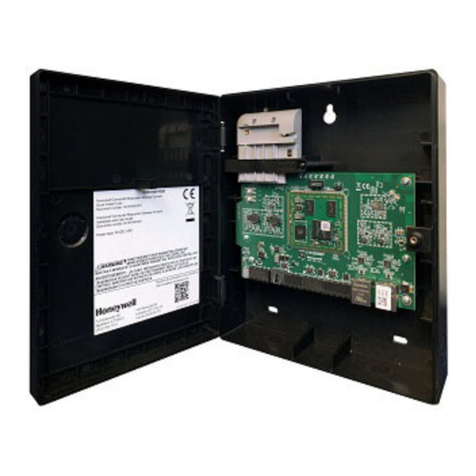
BENSHAW SPR-100P User manual

The Leader In
Solid State Motor Control
Technology
Publication #: 890010-00-04
REMOTE RTD
MODULE


TABLE OF CONTENTS
1. INTRODUCTION....................................... 4
1.1 How To Use This Manual.................................. 4
1.2 Product Description ..................................... 4
1.3 Theory of Operation ..................................... 4
2. TECHNICAL SPECIFICATIONS .............................. 6
2.1 Specifications......................................... 6
2.2 Physical ............................................ 7
3. INSTALLATION OF THE REMOTE RTD MODULE ..................8
3.1 Physical Installation ..................................... 8
3.2 Power Wire Connections .................................. 8
3.3 RS-485 Wiring ........................................ 8
3.4 RTD Wire Connections ................................... 9
3.5 Wiring Diagram ....................................... 9
4. COMMUNICATING WITH THE REMOTE RTD MODULE .............10
4.1 Modbus Communications ................................. 10
4.2 Modbus Input Registers................................... 10
4.3 Modbus Holding Registers ................................. 11
4.4 Modbus Commands ..................................... 11
4.5 Modbus Exception Responses ............................... 12
4.6 Indicating LEDs ....................................... 13
iii
TABLE OF CONTENTS

1.1 How To Use This Manual
General The Benshaw Remote RTD Module manual provides the following information;
•Product Description.
•Specifications.
•Installation.
•Use.
How To Use This Manual The Benshaw Remote RTD Module manual is divided into 4 sections;
•Introduction.
•Technical Information.
•Installation.
•Operation.
1.2 Product Description
General The Remote RTD Module is designed to monitor up to 8 RTDs and report their
temperatures across a serial communications link.
Features The RTD Module provides the following features;
•Monitors up to 8 3-wire RTDs.
•Lead Resistance Compensation.
•RTD open detection.
•RTD shorted detection.
•Modbus communications over RS-485.
1.3 Theory of Operation
General The Remote RTD Module makes a compensated measurement of a RTD (Resistive
Temperature Device). This is accomplished by using three wires to connect the RTD to
the module.
The Remote RTD module provides 10mA of current from H (Hot) and C
(Compensation) terminals. The two currents add at the RTD and 20mA is returned to
the R (Return) terminal. The following diagram illustrates this;
4
1. INTRODUCTION
R
C
H
Remote
RTD
Module
RTD
10mA
20mA
10mA
Compensation
Return
Hot

The connection wire from the Remote RTD Module to the RTD will typically have all
three conductors the same size and length. This means that the resistance of each
conductor will be the same. Call the resistance of each conductor Rlead.
From the above, the following equations can be seen;
V V V V = 20mA R +10mA R +10mA
RH R lead RTD H lead lead RTD=++ ´ ´ ´Rlead
V V V = 10mA R + 20mA RCR C lead R lead lead lead=+ ´ ´
Subtracting these two equations and subsituting Rlead for the different lead resistance
provides the following;
()()
V V 30mA R 10mA R 30mA RRH CR lead RTD lead-= ´ + ´ - ´
V V 10mA R
RH CR RTD-= ´
This calculation gives the voltage across the RTD independant of the connection wire
resistance. By performing this calculation, the Remote RTD Module compensates for
the conductor resistance and gets the true value for the RTD resistance.
The Remote RTD Module then converts the measured voltage across the RTD to the
temperature that the RTD is measuring. This is possible because the RTD conforms to
a standard resistance vs temperature curve.
5
1. INTRODUCTION

2.1 Specifications
General The following table lists the specifications for the RTD module.
Model Number SPR-100P
RTD Type 100WPlatinum, 3 lead
TCR (a)0.00385 W/W/°C
(DIN 43760)
Maximum Lead
Resistance
25Wper lead
Recommended Lead
Resistance
Less than 16Wper lead
Shorted Lead Detection <60W
Open Lead Detection > 260W
RTD Sensing Current 10 mA DC
RTD Sensing Voltage 10V DC maximum
Range 0to200°C (32 to 392 °F)
Resolution 1°C (1.8 °F)
Accuracy ±1.0% full scale (±2°Cor±3.6 °F)
Sampling Rate 1 RTD per second
Number of RTDs 8
Input Voltage 24 Volts DC ±20%
Power Consumption 2.5 Watts
Inrush Current 15 Amps for .5 m-seconds
Communication Type RS-485
Communication Protocol Modbus®RTU
Modbus®Addresses 16 to 23
Baud Rate 19200 bps
Operating Environment -40 to 60 °C (-40 to 140 °F), up to 95% R.H., non-condensing
Storage Environment Up to two years at -40 to 70 °C (-40 to 158 °F), up to 95% R.H., non-condensing
Terminal Strips Accepts one or two stranded copper wires of the same size from 12 to 30 AWG
Dimensions 5½"Wx3½"Hx2¼"D
Dust/Moisture IP20
Weight 12.5 ounces (356 grams)
Listing
6
2. TECHNICAL SPECIFICATIONS

2.2 Physical
Construction The following diagram shows the physical construction of the Remote RTD Module;
7
2. TECHNICAL SPECIFICATIONS

3.1 Physical Installation
Location The mounting location for the Remote RTD Module should be chosen to give easy
access to the RTD wiring as well as providing a location to mount the power supply.
The Remote RTD Module is specifically designed to be mounted close to the
equipment it is monitoring. This eliminates long RTD wire lengths which save time
and money on installation and wiring.
Site Requirements The installation location must meet the following specifications;
•Temperature: -40oCto60
oC.
•Humidity: up to 95%, non-condensing.
Mounting The Benshaw Remote RTD Module is designed to mount on industry standard 35mm
wide by 7.5mm deep DIN rail. The Remote RTD Module should be mounted in a
location that allows access to the control terminals and visual inspection of the
indicator LEDs.
Modbus Address Set the rotary switch on the top of the Remote RTD Module to the desired Modbus
address.
3.2 Power Wire Connections
Power Connections The 24VDC power source is connected to the following terminals.
•24VDC – - Negative connection to 24VDC power supply
•24VDC + - Positive connection to 24VDC power supply
•g- Chassis ground connection
3.3 RS-485 Wiring
RS-485 Communications The RS-485 communications wiring should use shielded twisted pair cable. The shield
should only be terminated at one end. The connections are as follows;
•A (–) - RS485 negative communications connection.
•B (+) - RS485 positive communications connection.
•Com - RS485 common connection.
RS-485 Cable Specification The RS-485 communications cable should conform to the following specification;
•Conductors - 2 twisted pair (one pair signal plus one for signal common).
•Gauge - 16 to 24 AWG stranded, tinned copper.
•Impedance - 100 to 120 Ohms.
•Capacitance - 15.5pF/ft. or less.
•Shield - Overall Shield.
RS-485 Topology The RS-485 network should be wired in a daisy-chain configuration. Avoid using star
or stub configurations.
RS-485 Shielding The RS-485 shield should be terminated at only one point in the network, preferably
at the master device. Do not connect the RS-485 shield to the RTD shield terminals.
RS-485 Termination A 120Wresistor may optionally be installed between the A(-) and B(+) terminals if the
Remote RTD Module is the end device on the RS-485 network. The terminating
resistor may be necessary if the RS-485 cable is extremely long. Do not install a
terminating resistor if the Remote RTD Module is not the end device on the network.
There should never be more than two terminating resistors on the network.
8
3. INSTALLATION OF THE REMOTE RTD MODULE

3.4 RTD Wire Connections
RTD Connections Each Remote RTD Module has connections for up to 8 RTDs. The terminals for the
RTD wires are as follows;
•R - RTD return wire.
•C - RTD compensation wire.
•H - RTD hot wire.
Each RTD is connected to the three terminals with the common number. For example,
RTD number 5 connects to the terminals numbered 5R, 5C, and 5H.
RTD Cable Specification Benshaw recommends using 3-wire twisted (triad) shielded cable to connect the RTDs
to the RTD module. It is important to keep the three wires of the same length and
type for accurate lead resistance compensation.
RTD Cable Shielding The RTD cable shield should be terminated at either of the shield terminals. For a
simpler installation, a cable containing multiple triads with an overall shield can be
used to connect a group of RTDs to the module with a single cable.
3.5 Wiring Diagram
General The following is the wiring diagram detailing the connections of the RTD module.
Only the wiring for RTD #5 is shown as the typical connection, but all the other RTDs
connect similarly.
9
3. INSTALLATION OF THE REMOTE RTD MODULE
RTD #5
(Typical)
H
C
R
RS-485 Master
Device
ComA(-)B(+)Shld
24 VDC
Power
Supply
V- V+
Tx RxStatus
8R8C8H7R7C7H6R6C6H5R5C5H Shld
4R4C4H3R3C3H2R2C2H1R1C1H Shld 24 VDC
+
B(+)A(-)Com
RS-485
Remote
RTD Module
BENSHAW
ADVANCED CONTROLS & DRIVES

4.1 Modbus Communications
General The Remote RTD Module uses an industry standard RS-485 port, communicating as a
Modbus RTU slave. The Remote RTD Module has the following communications
features;
•RS-485 port.
•19200 bits per second communications rate.
•8 data bits, 1 stop bit, no parity.
•Modbus RTU slave, addresses 16 to 23.
4.2 Modbus Input Registers
General The Benshaw Remote RTD Module has a number of Modbus input registers. These
registers are used to read the temperatures measured by the eight RTDs.
Registers The following table lists the Modbus input registers;
Register Description Values
30001 RTD 1 0 to 200 - Temperature in degrees Celsius
30002 RTD 2 0 to 200 - Temperature in degrees Celsius
30003 RTD 3 0 to 200 - Temperature in degrees Celsius
30004 RTD 4 0 to 200 - Temperature in degrees Celsius
30005 RTD 5 0 to 200 - Temperature in degrees Celsius
30006 RTD 6 0 to 200 - Temperature in degrees Celsius
30007 RTD 7 0 to 200 - Temperature in degrees Celsius
30008 RTD 8 0 to 200 - Temperature in degrees Celsius
30009 Shorted RTD A bit is set if an RTD has a shorted lead. Otherwise, it is
clear. The set bit is as follows;
Bit 0: RTD 1 shorted.
Bit 1: RTD 2 shorted.
Bit 2: RTD 3 shorted.
Bit 3: RTD 4 shorted.
Bit 4: RTD 5 shorted.
Bit 5: RTD 6 shorted.
Bit 6: RTD 7 shorted.
Bit 7: RTD 8 shorted.
Bits 8-15: unused.
30010 Open RTD A bit is set if an RTD has an open lead. Otherwise, it is
clear. The set bit is as follows;
Bit 0: RTD 1 open.
Bit 1: RTD 2 open.
Bit 2: RTD 3 open.
Bit 3: RTD 4 open.
Bit 4: RTD 5 open.
Bit 5: RTD 6 open.
Bit 6: RTD 7 open.
Bit 7: RTD 8 open.
Bits 8-15: unused.
10
4. COMMUNICATING WITH THE REMOTE RTD MODULE

4.3 Modbus Holding Registers
General The Benshaw Remote RTD Module has a single Modbus holding register. This
register is used to set the operating mode of the module. In normal mode, the RTD
module scans all eight RTDs at an update rate of 1 RTD per second. In test mode, it
continually monitors the chosen RTD. The default mode at power-up is normal mode.
Holding Register The following table list the Remote RTD Module holding register values;
Register Description Values
40001 Operation Mode 0 = Normal mode
1 = Test mode, RTD# 1
2 = Test mode, RTD# 2
3 = Test mode, RTD# 3
4 = Test mode, RTD# 4
5 = Test mode, RTD# 5
6 = Test mode, RTD# 6
7 = Test mode, RTD# 7
8 = Test mode, RTD# 8
4.4 Modbus Commands
General The Remote RTD Module supports the following Modbus commands;
•Read input registers (function code 04h).
•Read holding registers (function code 03h).
•Preset single register (function code 06h).
Format All Modbus messages have the following format;
Address Function code Data CRC-16
1 byte 1 byte n-bytes 2 bytes
Read Input Registers Function code 04h is used to read one or more consecutive input registers. The first
register read is 30001 plus the offset. For example, to read the temperature of RTD #4
(input register 30004), send the command;
Address Function
Code
Register Offset Number of
Registers
CRC-16
10h 04h 00 03h 00 01h C2 8Bh
If the temperature being read by RTD#1 was 123oC, the Remote RTD Module will
respond with the Modbus holding register in the following format;
Address Function
Code
Byte Count Register Data CRC-16
10h 04h 02h 00 7Bh 05 10h
11
4. COMMUNICATING WITH THE REMOTE RTD MODULE

Read Holding Registers Function code 03h is used to read the contents of the single Remote RTD Module
holding register. Since there is only one register available to read, using the register
offset of 00 00h will read the contents of register 40001. For example, to check the
mode of the Remote RTD Module, send the command;
Address Function
Code
Register Offset Number of
Registers
CRC-16
10h 03h 00 00h 00 01h 87 4Bh
If the Remote RTD Module is in the test mode for RTD#4, it will respond with the
following;
Address Function
Code
Byte Count Register Data CRC-16
10h 03h 02h 00 04h 45 84h
Preset Single Register Function Code 06h allows the Modbus master to write to the holding register in the
Remote RTD Module. This command allows the mode of the Remote RTD Module to
be set. For example, to set the Remote RTD Module to test mode so that it only
monitors the temperature of RTD#7, send the command;
Address Function
Code
Register Offset Register Data CRC-16
10h 06h 00 00h 00 07h CB 49h
The Remote RTD Module will respond with this echo of the command;
Address Function
Code
Starting
Register
Number of
Registers
CRC-16
10h 06h 00 00h 00 07h CB 49h
4.5 Modbus Exception Responses
General There are four different communications errors the Remote RTD Module will
recognize and respond to. They are;
•CRC Error
•Illegal Function (exception code 01)
•Illegal Data address (exception code 02)
•Illegal Data Value (exception code 03)
CRC Error If the Remote RTD Module receives a message that contains a CRC error, the received
message is ignored. No response is sent.
Illegal Function If the Remote RTD Module receives a message that is anything other than read
holding registers, read input registers, or preset single register (functions 03, 04, 06),
it will respond with and illegal function exception response. This response will be in
the form;
•Byte 1: RTD Module Address.
•Byte 2: The requested function code with the MSB set to 1 to indicate an
exception.
•Byte 3: Exception code 01h indicating an illegal function code.
•Byte 4: LSB of CRC code.
•Byte 5: MSB of CRC code.
12
4. COMMUNICATING WITH THE REMOTE RTD MODULE

For example, if a read coil status function (function code 01) is sent to the Remote
RTD Module, the following would be the response;
Address Function Code Exception Code CRC code
10h 81h 01h D1 95h
Illegal Data Address If the Remote RTD Module receives a supported command that refers to unsupported
registers, it will respond with an illegal data address exception response. This
response will be in the form;
•Byte 1: RTD module address.
•Byte 2: Function code with the most significant bit set to 1 to indicate an
exception.
•Byte 3: Exception code 02h indicating an illegal data address exception.
•Byte 4: LSB of CRC code.
•Byte 5: MSB of CRC code.
For example, if an attempt is made to read a holding register that does not have a
valid address, the Remote RTD Module will respond with the following;
Address Function Code Exception Code CRC code
10h 83h 02h 90 F4h
Illegal Data Value If the Remote RTD Module receives a preset single register command that contains an
illegal value, it will respond with and illegal data value exception response. The
response will be in the form;
•Byte 1: RTD module address.
•Byte 2: Function code with most significant bit set to 1 indicating an exception.
•Byte 3: Exception code 03h indicating an illegal value exception.
•Byte 4: LSB of CRC code.
•Byte 5: MSB of CRC code.
For example, the Remote RTD Module will respond with the following if it receives an
invalid preset single register command;
Address Function Code Exception Code CRC code
10h 86h 03h 52 64h
4.6 Indicating LEDs
Description There are three indicating LEDs. They perform the following functions;
•TX - On when the Remote RTD Module is transmitting data.
•RX - On when the Remote RTD Module is receiving data.
•Status - Blinks once per second in normal mode. Each flash corresponds to
the temperature measurement of one of the RTD inputs.
13
4. COMMUNICATING WITH THE REMOTE RTD MODULE


Revision History;
Revision Date ECO#
00 16/11/99
01 23/02/00
02 24/02/00
03 31/03/00
04 28/04/00 088

Sales and Service
United States
Pittsburgh, Pennsylvania
Dayton, Ohio
Syracuse, New York
Boston, Massachusetts
Wilmington, Delaware
Charlotte, North Carolina
Jacksonville, Florida
Birmingham, Alabama
Los Angeles, California
Detroit, Michigan
LaCrosse, Wisconsin
Chicago, Illinois
St. Louis, Missouri
Phoenix, Arizona
Seattle, Washington
Denver, Colorado
Houston, Texas
Canada
Listowel, Ontario
Toronto, Ontario
Montreal, Quebec
Calgary, Alberta
South America
Sao Paulo, Brazil
Santiago, Chile
Singapore
BENSHAW Inc.
1659 East Sutter Road
Glenshaw, PA 15116
Phone: (412) 487-8235
Fax: (412) 487-4201
BENSHAW West
14715 North 78th Way
Suite 600
Scottsdale, AZ 85260
Phone: (480) 905-0601
Fax: (480) 905-0757
BENSHAW Canada
550 Bright Street,
Listowel, Ontario
N4W 3W3
Phone: (519) 291-5112
Fax: (519) 291-2595
Visit us at:
http://www.benshaw.com
Distributed by:
BENSHAW PRODUCTS
•Pump Duty Starters
•Wound Rotor Starters
•Chiller/Compressor Starters
•Synchronous Motor Starters
•Synchronous Motor Field
Controllers
•Medium Voltage Starters
•D.C. Injection Brakes
•Solid State Contactors
•Variable Voltage Controllers
•Invertors
Table of contents
