4 3RM/24VAC Installation Instructions TG200647 Issue 3, 27-Mar-2015. .
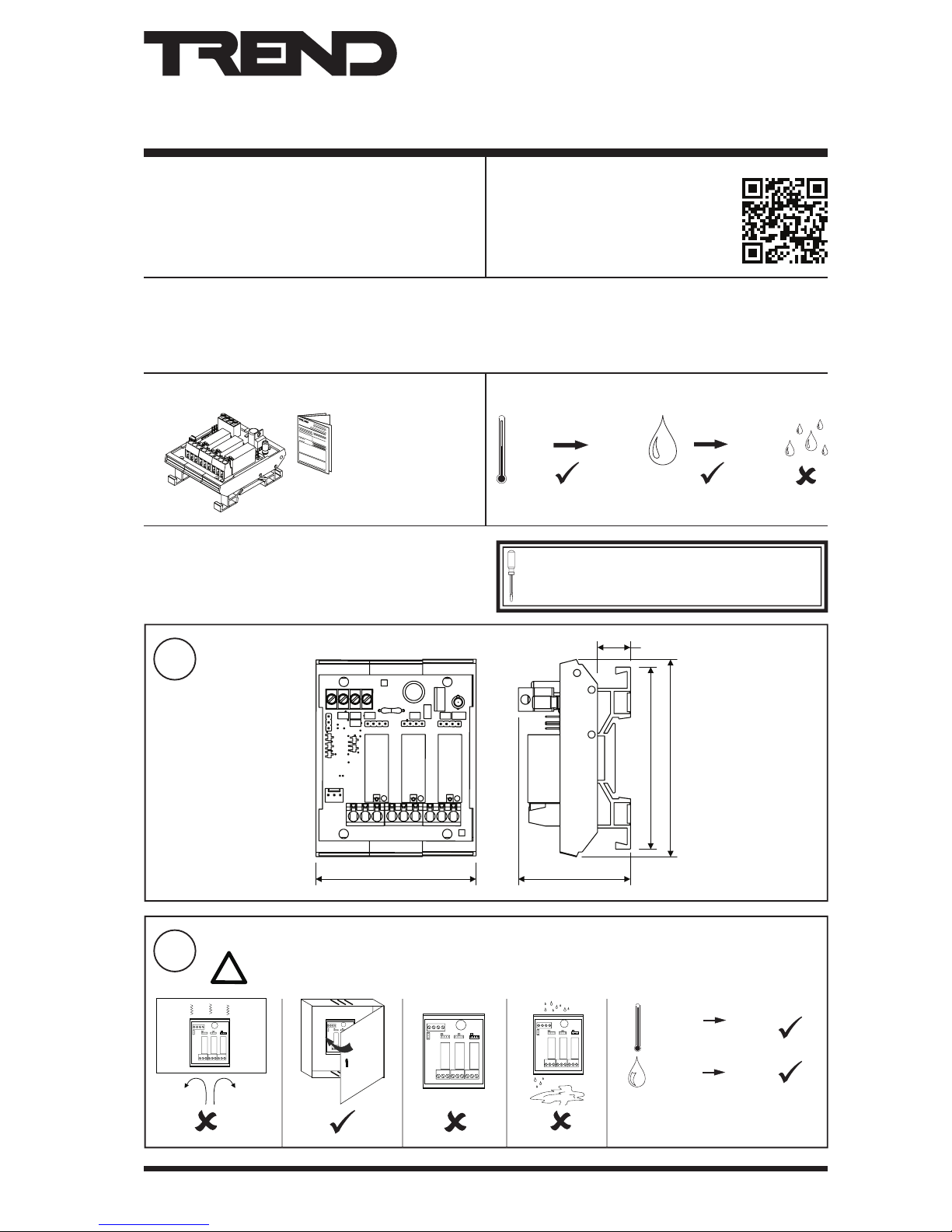
3RM/24VAC Installation Instructions - Mounting
Please send any comments about this or any other Trend technical
© 2015 Honeywell Technologies Sàrl, ECC Division. All rights reserved. Manufactured for and on behalf of the Environmental and Combustion Controls
Division of Honeywell Technologies Sàrl, Z.A. La Pièce, 16, 1180 Rolle, Switzerland by its Authorized Representative, Trend Control Systems Limited.
Trend Control Systems Limited reserves the right to revise this publication from time to time and make changes to the content hereof without obligation
to notify any person of such revisions or changes.
Trend Control Systems Limited
Albery House, Springeld Road, Horsham, West Sussex, RH12 2PQ, UK. Tel:+44 (0)1403 211888 Fax:+44 (0)1403 241608 www.trendcontrols.com
TR CU Certication
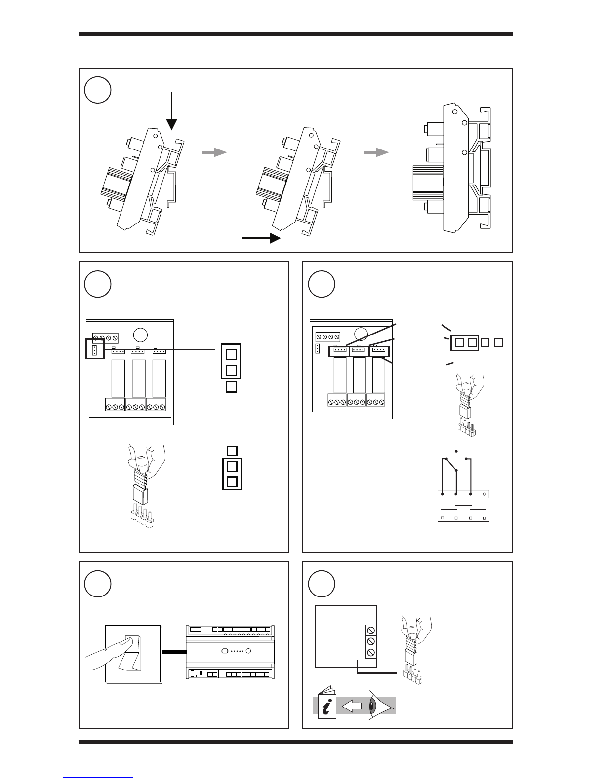
15 Check Relay Operations
14 Switch on HVAC Equipment Power
Supply
13 Switch On Controller
11 Congure Controller 12 Close panel
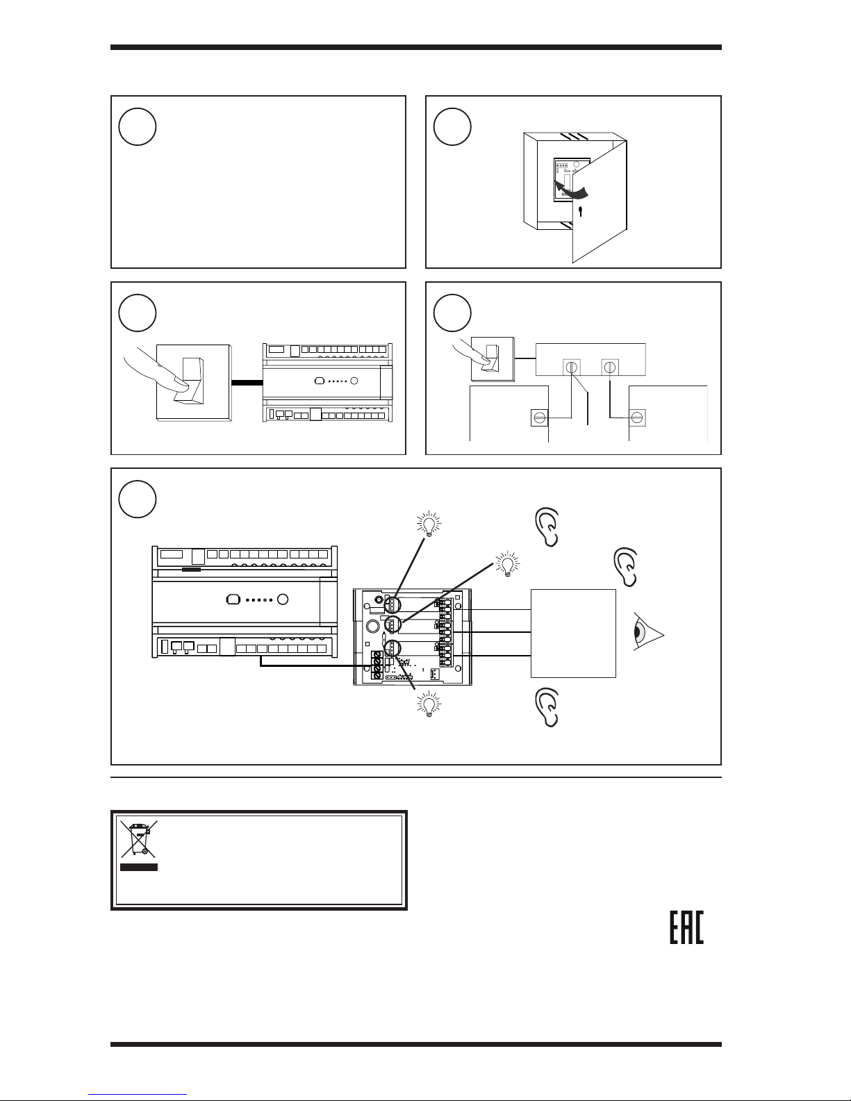
4 DISPOSAL
WEEE Directive:
At the end of their useful life the packaging and
product should be disposed of by a suitable
recycling centre.
Do not dispose of with normal household waste.
Do not burn.
3 INSTALLATION (continued)
Note that the AUTO/ON/OFF links may be used to test 3RM to HVAC Equipment installation, however, when using manual
overrides (ON, OFF), feeds switched from other relays on the same module, or interlocks with other relays may not be operative.
‘click’
3RM
HEAT/HIGH
‘click’
FAN/LOW
‘click’
COOL/MID
Equipment
Use SET (software tool) for conguring the controller. SET
is suppied with 3RM strategy blocks for IQ1, IQ2, IQ3 and
IQ4 controllers.
There are 3 strategy blocks: HCM mode, TRM mode/
analogue driver, HCM mode/RL driver