Bentone BF 1 KSV RME Technical specifications

Providing sustainable energy solutions worldwide
CR00174 178 156 35-3 2021-07-09
Installation- and maintenance instruction
BF 1 KSV RME
LMO14.113C2E
ANV47C
Translation of the original instructions.

2Bentone
example Beispielexempel
352011030141
Designation
Type
Model
Serial no.
Motor supply
Main supply
MADE IN SWEDEN BY
LIGHT OIL 35-90kW 1,25-6,0 cSt 7-14bar
BF 1 KS 76-24
BF 1
BF 1 KS 76-24
1234567
1~230V 1,0A 50Hz IP 20
Man.Year 2019
Cap. Min-Max
3
?
1
-sv
1. Manualer på övriga språk
2. www.bentone.com\
nedladdning
eller scanna QR-koden.
3. Skriv in brännarens
artikelnummer som finns på din
typskylt (se bild) och välj ditt
språk.
Detaljerad ecodesign information
kan laddas ner på:
www.bentone.com/ecodesign.
-en
1. Manuals in other languages
2. www.bentone.com\download
or scan QR-code.
3. Enter the burner`s article
number on your data plate (see
picture) and select language.
Detailed ecodesign information
can be downloaded at:
www.bentone.com/ecodesign.
-da
1. Manualer på andre sprog
2. www.bentone.com\download
eller scan QR-koden.
3. Indtast brænderens
artikelnummer, der findes på
typeskiltet (se billede), og vælg
dit sprog.
Detaljerede oplysninger om
ecodesign kan downloades på:
www.bentone.com/ecodesign.
-fr
1. Manuels dans d’autres
langues
2. www.bentone.com\download
ou scannez le code QR.
3. Saisir le numéro d’article
du brûleur sur votre plaque
signalétique (consultez
l’illustration) et sélectionnez la
langue.
Des informations détaillées
sur l’écodesign peuvent être
téléchargées à l’adresse:
www.bentone.com/ecodesign.
-de
1. Gebrauchsanweisungen in
anderen Sprachen
2. www.bentone.com\download
oder scannen Sie den QR-Code.
3. Geben Sie die Artikelnummer
des Brenners auf Ihrem
Typenschild ein, (siehe Bild) und
wählen Sie die Sprache aus.
Detaillierte Informationen zum
Ecodesign können unter
www.bentone.com/ecodesign
heruntergeladen werden.
2

3Bentone
Table of contents
1. Safety Information____________________________________ 4
2. Technical data _______________________________________ 8
2.1 Model BF 1 KS/KSV 76-24 _________________________ 9
2.2 Recommended nozzles and pressures ______________ 10
2.3 Description______________________________________ 11
3. Installation _________________________________________ 13
3.1 Delivery checks __________________________________ 13
3.2 Preparations for installation ________________________ 13
3.3 Oil supply _______________________________________ 13
3.4 Electrical connection______________________________ 13
3.5 Choice of nozzle _________________________________ 13
3.6 Brake plate and airflow setting _____________________ 13
3.7 Burner installation ________________________________ 14
4. Basic settings ______________________________________ 15
4.1 Example of basic setting __________________________ 15
5. Burner servicing ____________________________________ 18
5.1 Warning ________________________________________ 18
6. Pump Instructions___________________________________ 27
6.1 Suntec ANV47C _________________________________ 27
7. Preheater___________________________________________ 31
8. Oil Burner Control ___________________________________ 32
8.1 Wiring diagram _________________________________ 32
8.2 Function LMO14/24 ______________________________ 33
8.3 Colour codes LMO14/24 __________________________ 34
8.4 Fault codes LMO14/24 ___________________________ 34
9. Fault Location ______________________________________ 35
9.1 Burner will not start_______________________________ 35
9.2 Burner will not start after normal use ________________ 35
9.3 Delayed ignition__________________________________ 36
9.4 Noise in pump ___________________________________ 36
9.5 Pump pressure __________________________________ 37
10. Log of flue gas analysis____________________________ 38
11. Oil burners maintenance instructions _______________ 39
4Bentone
1. Safety Information
This Installation and Maintenance manual:
• is to be regarded as part of the burner and must always be kept near
the installation site
• is intended for use by authorised personnel
• must be read prior to installation
• must be observed by all who work with the burner and associated
system components
• work with the burner may only be carried out by certified installers/
personnel
• Enertech AB is not liable for any typographical errors and reserves the
right to make design changes without prior notice.
• The burner may only be used for its intended purpose in accordance
with the product’s technical data.
• The burner may only be installed and operated by authorised
personnel.
• The product is packaged to prevent damage from occurring during
handling. Handle the product with care. Lifting equipment must be
used to lift larger packages.
• The products must be transported/stored on a level surface in a dry
environment, max. 80% relative humidity, no condensation.
Temperature -20 to +60 °C.
• Check that the burner is compatible with the boiler’s output range.
• The label information on the rating plate refers to the burner’s minimum
and maximum power.
• All components must be installed without being bent, twisted or
subjected to mechanical or thermal forces which can affect the
components.
• The burner must be installed so that it complies with local regulations
for fire safety, electrical safety, and fuel distribution.
• Make sure when installing the equipment that there is enough space to
service the burner.
• Permitted ambient temperature during operation 0 to +60°C. Max
80% relative humidity, no condensation.
• The installer must ensure that the room has adequate air supply.
• The room must comply with local regulations pertaining to its intended
use.
• The installation site must be free of chemicals.
• Burner tubes, fan wheels and air dampers may contain sharp edges.
• The surface temperature of the burner’s components can exceed
60°C.
• Caution: The burner has moving parts, and there is risk of crushing
injuries.
• The electrical installation must be professionally carried out in
accordance with applicable high voltage regulations, as per Enertech’s
recommendations.
165 105 85

5Bentone
• Before service, shut off the fuel supply and turn off the power to the
burner.
• Leak checks must be performed during installation and service to
prevent fuel leakage.
• Care should be taken by the installer to ensure that no electrical cables
or fuel lines are crushed or otherwise damaged during installation or
service.
• If the boiler is equipped with an access hatch, this must be equipped
with a hatch opening switch connected to the burner's safety system.
• When in operation, the burner’s noise level can exceed 85 dBA.
Use hearing protection.
• The burner must not be put into operation without proper safety and
protection devices.
• Fire extinguisher with Class BE recommended.
• Modifying the design or using accessories that have not been
approved by Enertech in writing is strictly prohibited.
• Prior to operation, the following points must be checked:
-fitting and installation work has been completed and approved
-electrical installation has been correctly performed
-flue gas ducts and combustion air ducts are not blocked
-all actuators and control and safety devices are in working order and
correctly set
• After commissioning
-If the gas burner control has a solid red light, contact your installer.

6Bentone
General requirements RME
This is a burner designed for FAME, B-100 (RME) fuel. The fuel must meet
the requirements of standard EN 14214 for FAME.
The fuel must be stored and used according to the manufacturer’s
instructions. It should typically be used within 6 months of manufacture. Fuel
that is allowed to age loses its oxidation stability and produces aggressive
constituents. These cause oxidation damage to components in the oil
system. The fuel should be stored in a cool area to minimise these problems.
The RME cistern must be made of metal or dark coloured plastics approved
for the fuel.
The design of the equipment on the burner permits the use of EO1 type
oil without modification, although with appropriate adjustments to the
combustion after changing the fuel type.
Oil burners must be installed in accordance with local regulations. The
installer must therefore be knowledgeable of the regulations pertaining to oil
and combustion.
Installation should be carried out as a one-pipe system and used together
with the bleeder to vent the system, and an appropriate filter must also be
in place. Copper should be avoided in RME fuel systems since the fuel and
copper have an oxidising effect on each other.
Only oil suitable for the burner must be used and then in combination with
a suitable oil filter designed for FAME, B-100 (RME) and installed before the
burner’s oil pump.
The tank should be cleaned and the water should be checked regularly to
prevent problems related to corrosion and microorganisms. This should be
done once a year.
If the burner is replacing an existing burner, ensure that the oil filter is
changed to a filter designed for FAME, B-100 (RME). Installation may only be
performed by qualified personnel.
Care should be taken by the installer to ensure that no electrical cables or oil/
gas pipelines are crushed or damaged during installation or service.
Burners that run on FAME, B-100 (RME) fuel are and must be equipped with
parts designed for this fuel. This applies in particular to oil-related parts such
as the pump, solenoid valve, oil filter and hoses with fire-retardant sleeves. It
is very important when carrying out a service to replace old parts with new
parts of the same quality.
Maintenance
The boiler/burner must be checked regularly for faults or leakage. Any boiler/
burner that uses FAME (RME) fuel must be serviced at least twice a year. It is
very important that worn parts are replaced at the time of servicing with new
parts of the same quality.
Oil hoses must be of high-quality fluoride rubber or PTFE intended for FAME,
B-100 (RME).
The hoses must be fitted with fire-retardant sleeves in order to satisfy
requirements according to EN-ISO 6806.

7Bentone
Components Service life – Recommended
replacement
Service life – Recommended
replacement Operating cycles
Control system 10 years 250,000 cycles
Pressure switch 10 years 250,000 cycles
Ignition system with flame guard 10 years 250,000 cycles
UV flame sensor 10,000 h N/A
Damper motor 500,000 cycles
Contactor 10 years 500,000 cycles
Burner Twice a year 3,000 h
Filter Twice yearly replacement 3,000 h replacement
Oil hose Once yearly replacement
Nozzle Twice yearly replacement 3,000 h replacement
Electrodes Replace/Clean twice a year Replace/Clean 3,000 h
Brake disc Replace/Clean twice a year Replace/Clean 3,000 h
Motor Twice a year 3,000 h
Drive shaft Check/replace in the event of
damage
Check/replace in the event of
damage
Fan wheel Twice a year
Replace if
need for cleaning/imbalance
3,000h
Replace if
need for cleaning/imbalance
Tank Check for water once a year
Clean tank once a year
Oil filter Twice a year 3,000 h replacement
Oil valve Tightness check twice a year Replace if leaky
The burner and its components must be recycled according to applicable regulations.
Burner service schedule
Servicing must be carried out twice a year or after 3,000 hours of operation.
Component replacement intervals
Delivery check
• Make sure everything is delivered and the goods have not been damaged during transit.
• If something is wrong with a delivery, report it to the supplier.
• Transport damage must be reported to the shipping company.
8Bentone
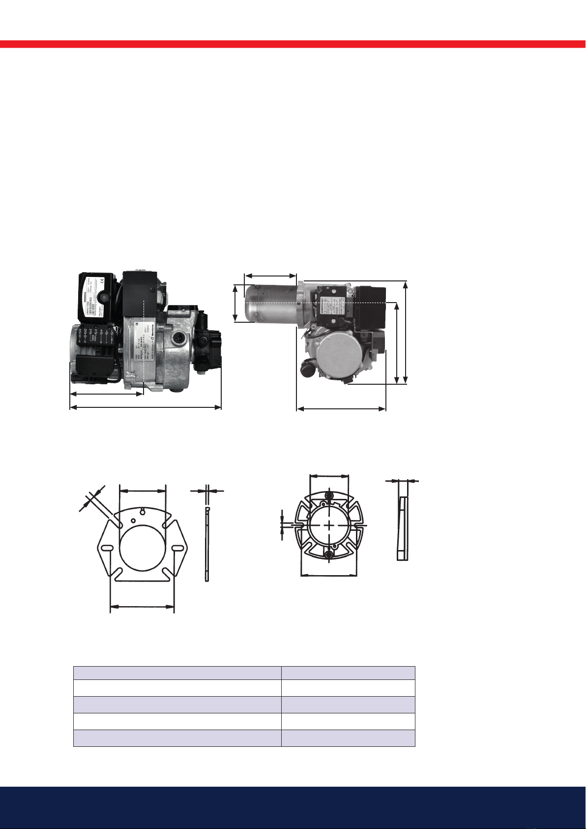
165 305 56
ø89
172
B
190
226
278
145
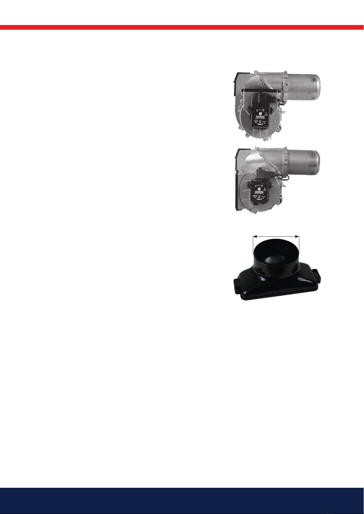
Dimensions, flanges
Flange 2
10,3
25
130–150
ø89,7
Flange 1
125–150
ø90 5
10,3
Electrical specification EN 60335-2-102
Type BF 1
Electrical data, Control power 230V 1~ 1,1/1,5A 50/60Hz IP20
Electrical data, Motor -
Max fuse rating 10A
Noise level 70 dBA
Max operating current, see data plate.
2. Technical data
The burner is intended for:
• Light oil, B10 heating oil/biofuel blend, FAME, B-100 (RME) (as defined in DIN V51603-6).
and is used for:
• Water heating generators.
• Hot air generators (these require LMO 24 255 C2E).
Dimensions BF 1

9Bentone
ø73
ø24
ø76
10,0-11,0
2,3-3,1 0,5-1,5
Length of blast tube
Protrusion from flange, measurement B
Flange 1 Flange 2
147 130 114
224 207 191
Working area/Basic settings
!Do not exceed the
working area.
!Scale value applies
to 0 mbar furnace
pressure.
0,0
2,0
4,0
6,0
8,0
10,0
12,0
14,0
16,0
18,0
20,0
22,0
35 40 45 50 55 60 65 70 75 80 85 90
160302-781-2
kW
Air settings
Nozzle assembly
Scale
Burner output
-
0,5
0,0
0,5
1,0
1,5
2,0
2,5
3,0
3,5
4,0
30 35 40 45 50 55 60 65 70 75 80 85 90 95
mbar
kW
3.0-7.6 kg/h
35-90 kW
160303-296
2.1 Model BF 1 KS/KSV 76-24

10 Bentone
2.6 Recommended nozzles and pressures
Because of the different types of boiler in existence, with varying furnace
geometries and furnace loads, it is not possible to commit to any given spray
angle or spay pattern. Note that spray angles and spray patterns change
with pump pressures.
Nozzle 60° Solid/Hollow cone
80° Solid/Hollow conel
Pump pressure 10 bar (8–14 bar) Fuel oil 1
10 bar (7–12 bar) Kerosene
Nozzle table, 8-15 bar
Pump pressure, bar
Gph 8 9 10 11 12 13 14 15
kg/h kW kg/h kW kg/h kW kg/h kW kg/h kW kg/h kW kg/h kW kg/h kW
0,40 1,33 16 1,41 17 1,49 18 1,56 18 1,63 19 1,70 20 1,76 21 1,82 21
0,50 1,66 20 1,76 21 1,86 22 1,95 23 2,04 24 2,12 25 2,20 26 2,28 27
0,60 2,00 24 2,12 25 2,23 26 2,34 28 2,45 29 2,55 30 2,64 31 2,73 32
0,65 2,16 26 2,29 27 2,42 29 2,54 30 2,65 31 2,75 33 2,86 34 2,96 35
0,75 2,49 29 2,65 31 2,79 33 2,93 35 3,08 36 3,18 38 3,30 39 3,42 40
0,85 2,83 33 3,00 36 3,16 37 3,32 39 3,47 41 3,61 43 3,74 44 3,87 46
1,00 3,33 39 3,53 42 3,72 44 3,90 46 4,08 48 4,24 50 4,40 52 4,56 54
1,10 3,66 43 3,88 46 4,09 48 4,29 51 4,48 53 4,67 55 4,84 57 5,01 59
1,20 3,99 47 4,24 50 4,47 53 4,68 55 4,89 58 5,09 60 5,29 63 5,47 65
1,25 4,16 49 4,40 52 4,65 55 4,88 58 5,10 60 5,30 63 5,51 65 5,70 68
1,35 4,49 53 4,76 56 5,02 59 5,27 62 5,50 65 5,73 68 5,95 70 6,15 73
1,50 4,98 59 5,29 63 5,58 66 5,85 69 6,11 72 6,36 75 6,60 78 6,83 81
1,65 5,49 65 5,82 69 6,14 73 6,44 76 6,73 80 7,00 83 7,27 86 7,52 89
1,75 5,82 69 6,18 73 6,51 77 6,83 81 7,14 85 7,42 88 7,71 91 7,97 94
2,00 6,65 79 7,06 84 7,45 88 7,81 93 8,18 97 8,49 101 8,81 104 9,12 108
2,25 7,49 89 7,94 94 8,38 99 8,78 104 9,18 109 9,55 113 9,91 117 10,26 122
The table applies to oils with a viscosity of 4.4 mm2/s (cSt) at a density of 830 kg/m3.
Burner with preheater
Allow for a reduction in oil quantity of 5–20% with preheating owing to:
• Temperature increases at the nozzle.
• Nozzle design.
• Capacity (the higher the capacity the lower the difference).
2.2 Recommended nozzles and pressures
11Bentone
23 4
7
1
10
5
6
8
9
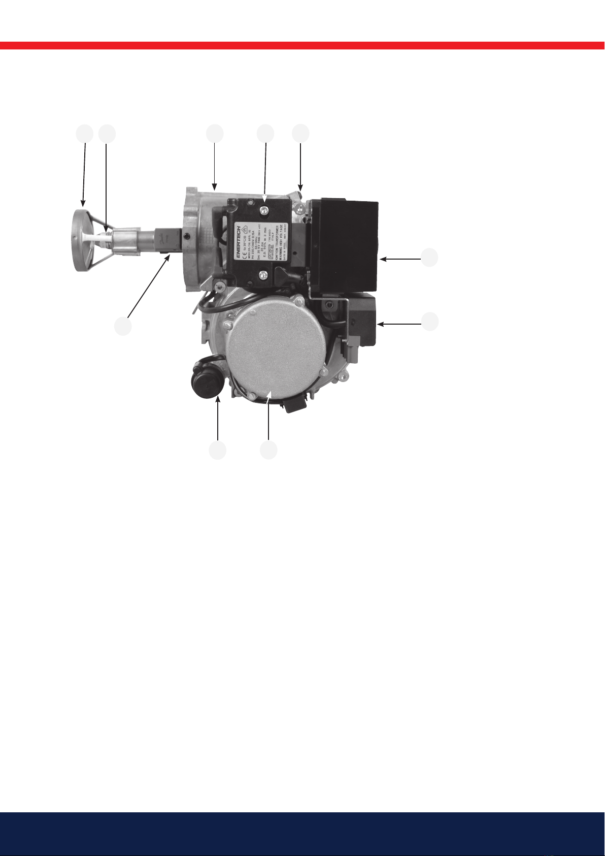
2.3 Description
Components
1. Brake plate
2. Nozzle
3. Fan housing, front
4. Ignition transformer
5. Separating screw
6. Oil burner control
7. Electrical contact X1 (refer to wiring diagram)
8. Motor
9. Capacitor
10. Preheater, where fitted
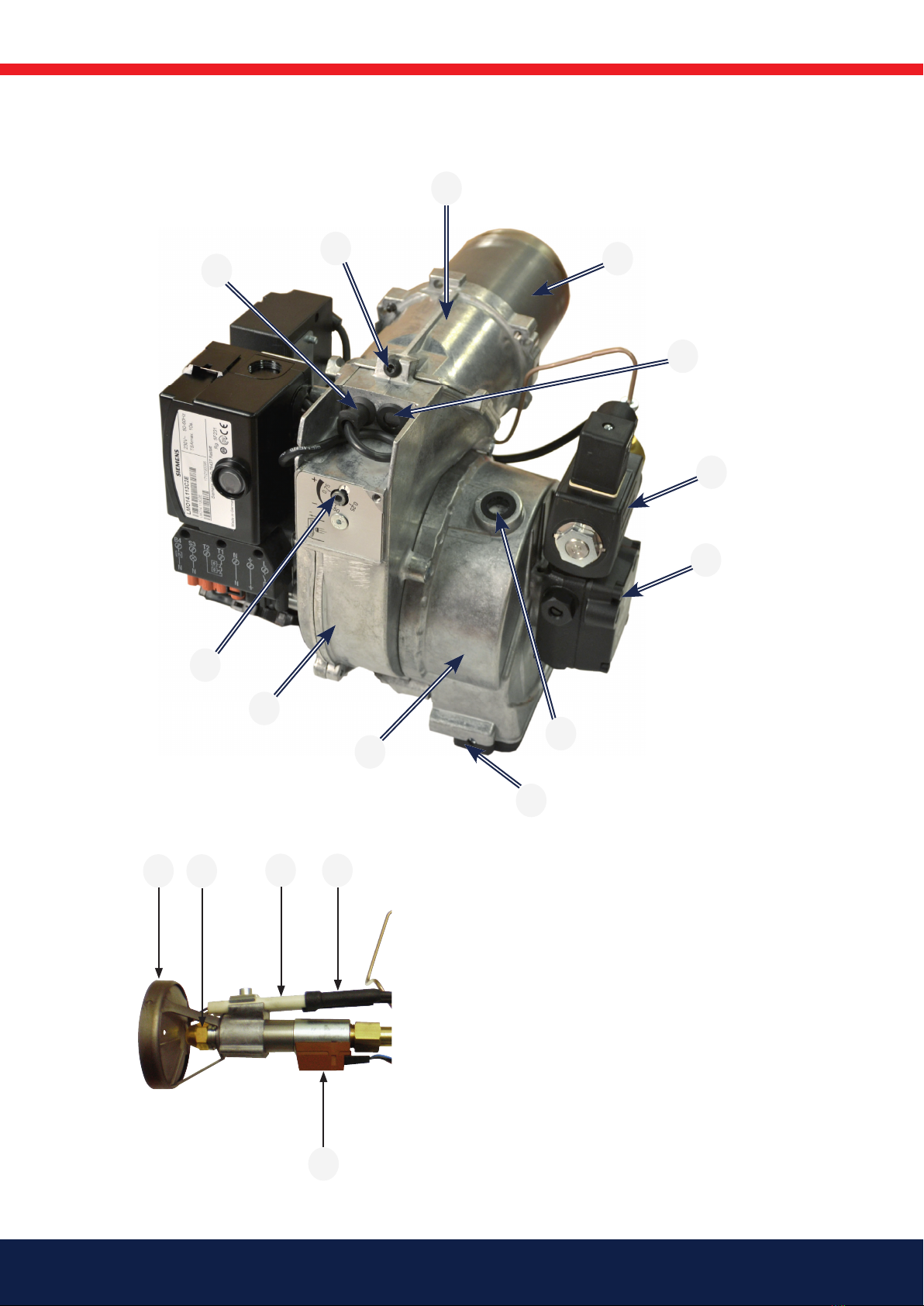
11. Ignition electrode
12. Ignition cable
13. Photoresistor
14. Inspection glass
15. Nozzle assembly adjustment
16. Cover plate
17. Blast tube
18. Grid
19. Solenoid valve
20. Oil pump
21. Air regulator
22. Air intake
23. Air flow indicator
24. Fan housing, rear
12 Bentone
211 12
1
10
5
15
24
22
21
23
13
3
17
14
19
20

13Bentone
165 305 18
3. Installation
3.1 Delivery checks
Check that everything has been delivered and that the goods are not
transport damaged. Any delivery faults must be reported to the supplier.
Transport damage must be reported to the forwarder.
3.2 Preparations for installation
Check that the burner’s measurements and capacity range is suitable for
the boiler in question. The power information on the data plate refers to the
burner’s max. and min. power.
3.3 Oil supply
In order to achieve good operational reliability it is important that the oil
supply system is laid out correctly.
Observe the following:
• Choice of pipe diameters, pipe lengths and height differences (refer to
pump instructions).
• Piping should be run with a minimum of joints/compression fittings.
• Pipework must be laid out so that oil hoses are not subjected to
tension or overbending when the burner is swung out or removed for
service.
• The oil filter should be installed so that the filter cartridge can easily be
replaced
3.4 Electrical connection
Before electrical installation is begun, electricity must be switched off at
the main switch. If the boiler has a 7-pole or a 4-pole Eurostecker (only on
2-stage burners), these often fit directly to the burner. Otherwise use the
connectors supplied. The operating thermostat, the max. thermostat and the
inspection hatch (where fitted) interlock can then be wired in series on the
incoming phase connected to L1 or connected between T1 and T2. In the
first mentioned case a jumper is installed between T1 and T2.
(Refer to connection in the section Electrical equipment).
3.5 Choice of nozzle
(Technical data): Recommended nozzle and nozzle table.
3.6 Brake plate and airflow setting
Before operations basic burner setting may be made according to the
diagram. (Refer to basic settings). Note that this only refers to the basic
setting; the setting must be adjusted after the burner has been started.
At this time flue gas analysis and soot measurement must be carried out.
!If any electrical connection is used other than that recommended by Enertech,
there may be a risk of equipment damage and personal injury.

14 Bentone
E
Return Inlet
E
X1
X2
3.7 Burner installation
3.7.1 Hole pattern
Check that the hole pattern matches the flange supplied.
(Refer to Technical data.)
3.7.2 Burner installation
1. Install the flange and the gasket on the boiler.
2. Attach the front piece to the flange.
3. Insulate between the burner register and the boiler cover for reduced
heat radiation.
4. Install the selected nozzle. (Refer to Technical data.)
5. Install the brake plate and check the ignition electrodes (refer to Burner
service.).
6. Install the burner body to the front piece and lock with screw (E).
3.7.3 Oil pipes
1. Check the oil pipe dimensions. (Refer to Pump Instructions.)
2. The oil filter should be installed in the oil supply line. If an air separator is
fitted, the oil filter should be installed before the air filter to increase the
life span of the filter.
3. For one-pipe systems the return plug must be removed. (Refer to
Pump Instructions.)
4. When installing oil hoses, check that the supply and return hoses are
connected to the correct connections on the oil pump. The hoses
must be run so that they are not bent or tensioned.
5. Purge the oil system. The oil pump will be damaged if it is run dry.
6. The vacuum should not be lower than 0.3 bar depression in the suction
line at start up.
3.7.4 Electrical connection
If the boiler lacks ready-connected plugs, connect using the supplied plug,
X2 in accordance with the wiring diagram.
1. Disconnect the power at the main switch.
2. Wire the Eurostecker X2 as in alt. 1–3 (refer to Electrical equipment).
3. Connect the Eurostecker X2 to the burner.
4. Switch on the power at the main switch.

15Bentone
165 305 19
4. Basic settings
4.1 Example of basic setting
4.1.1 Choice of nozzle
BF1 FU 63-16
Burner output 30 kW
Estimated nozzle output: 30 / 11,86* = 2,53 kg/h
Choice of nozzle according to table. (Refer to Technical data.)
According to the nozzle table, the following nozzle is indicated:
Nozzle: 0,65 Gph
Pump pressure: 11,0 bar
BF1 FU 63-16/FUV 63-16
Burner output 30 kW
Because of preheater, output is adjusted upward for choice of nozzle
according to table.
Estimated nozzle output: 30 x 1,06 = 31,8 kW
31,8 / 11,86* = 2,68 kg/h
Choice of nozzle according to table. (Refer to Technical data).
According to the nozzle table, the following nozzle is indicate
Nozzle: 0,75 Gph
Pump pressure: 9,5 bar
* Calorfic value Light oil = 11,86 kWh/kg
4.1.2 Basic setting
Setting values for 30 kW according to basic settings tables.
(Refer to Technical data FU 63-16).
Air setting = 11,0
Insert setting = 4,0

16 Bentone
Ι
Π
M
4.1.3 Nozzle assembly adjustment
The burner is fitted with a regulator which changes the brake plate position
in the blast tube. This is used to set the correct pressure drop across the
combustion assembly and thereby achieve good combustion without
pulsation.
The setting to be chosen is dependent among other things on set output
and furnace pressure.
Brake plate setting
• Less diffusion: turn screw to left.
• More diffusion: turn to right.
Setting brake plate position affects air flow. It is therefore always
necessary to adjust the air with the burner air regulator afterwards.
4.1.4 Air intake adjustment
Air settings are very important for achieving good combustion with neither
too much, nor too little, air. Adjustment of combustion airflow is carried out
by turning the air regulator with an Allen key. How far open the air regulator
must be is determined by output, furnace pressure and other burner settings
such as blast tube position.
4.1.5 Method of adjusting air quantity
Setting the air regulator is dependent on how the screw (with which air
regulation is adjusted) is installed. If the air intake is installed underneath
as shown in illustration Ι, turning the screw clockwise will reduce airflow,
and anticlockwise increase it. If the air intake is installed on top as shown
in illustration Π, clockwise adjustment increases airflow, and anticlockwise
reduces it.
4.1.6 Inlet cone, air adjustment
Airflow is also affected by the position of the inlet cone. However, it is
extremely rare that this needs to be adjusted; it should be left in the
standard STD position to achieve good starts and operations. (A cast-in
arrow on the fan housing indicates the position of the inlet cone. In addition
to the scale on the inlet cone casting, there is also a mark (M) indicating the
factory setting.)
17Bentone
D
4.1.7 Air intake rotation
It is possible to rotate the air intake to adapt the burner to different
surroundings. It is possible to rotate the air intake to a number of positions,
not just the positions shown to the left.
To rotate the air intake, undo the three screws that fasten the air intake and
the two screws which retain the pump. Then rotate the air intake to the
desired position and tighten the screws.The position of the air intake affects
the airflow through the burner somewhat.
The position which provides best airflow is with the air intake pointing
downwards.
4.1.8 Air duct
A hose connection air duct is available in three different dimensions: 48, 68,
and 78 mm outer diameter (D). The air duct is installed on the air intake at
the place where the grille is attached in the standard model
18 Bentone
165 305 51
!
Warning
!When servicing or replacing components that affect combustion, analyses and
soot tests must be carried out on the installation.
5. Burner servicing
5.1 Warning
Service must be carried out after 3,000 operating hours, or at least once per
year.
Only authorized personnel may perform service.
Before any type of service work is begun, switch of the power at the main
switch and shut off the oil.
Exercise caution as parts which are exposed when the burner is taken apart
can be hotter than 60°C. The installation engineer must be especially careful
to ensure that no electrical wiring or oil lines are pinched or damaged during
installation or service.
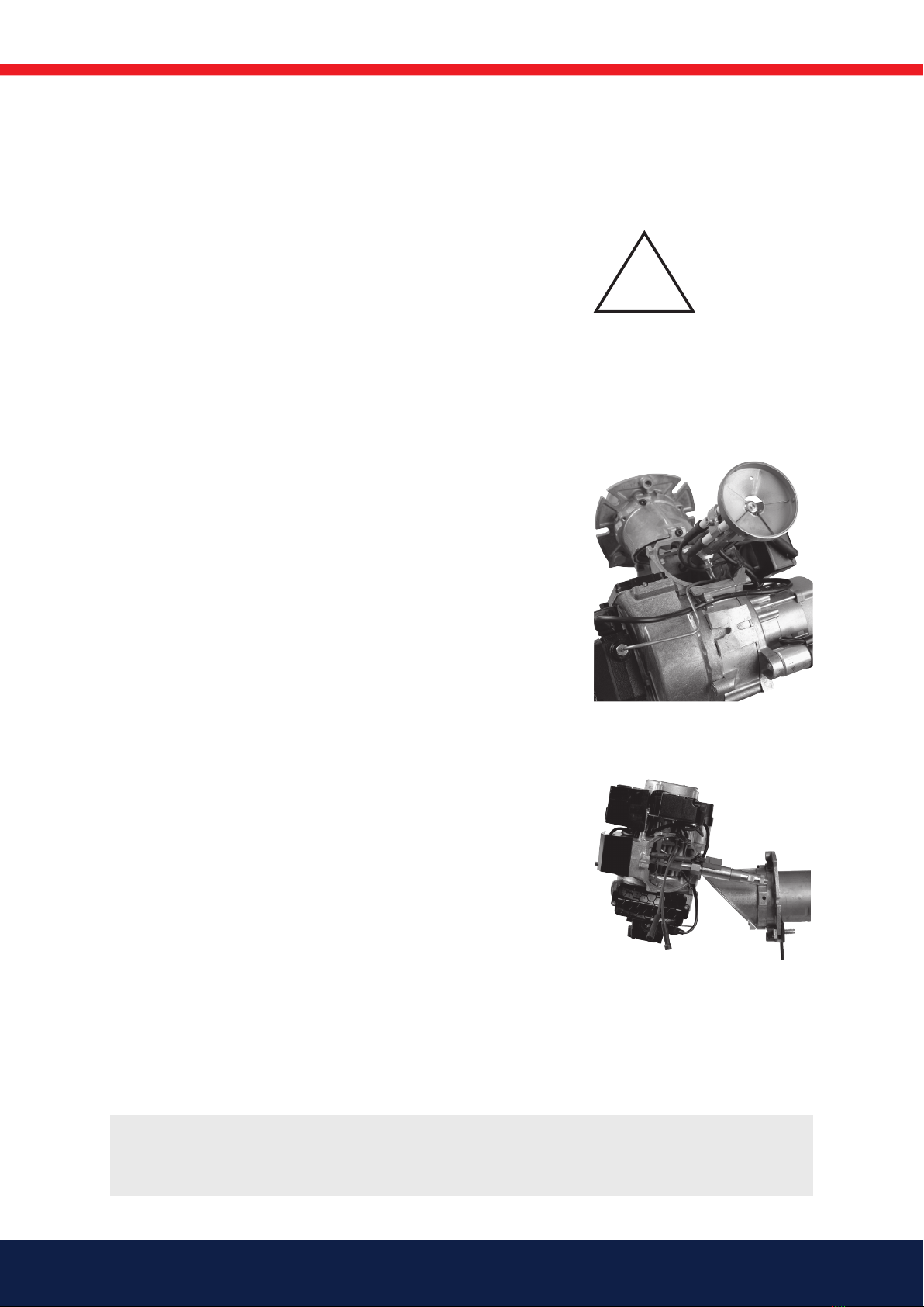
5.1.1 Service position
5.1.1.1 Service position 1
1. Switch off the power at the main switch and disconnect the Eurostecker
from the burner.
2. Undo the screw which fastens the burner front piece to the fan housing,
but only so much as to allow the fan housing to be removed from the
burner front piece.
3. Remove the fan housing from the burner front piece and pull it
backwards until the combustion assembly is free of the burner front
piece.
4. Suspend the fan housing by the fan housing attachment point (for
joining the front piece to the fan housing) on the screw (for joining the
front piece to the fan housing) as illustrated to the left. If necessary,
tighten the screw somewhat to ensure that the burner is suspended
safely.något för att få brännaren att hänga säkrare.
5.1.1.2 Service position 2
1. Switch off the power at the main switch and disconnect the Eurostecker
from the burner.
2. Undo the screw which fastens the burner front piece to the fan housing,
but only so much as to allow the fan housing to be removed from the
burner front piece.
3. Remove the fan housing from the burner front piece and pull it
backwards until the combustion assembly is free of the burner front
piece.
4. Turn the screw into the front piece until there is a gap of approx. 5 mm
between the metal and the screw head.
5. Suspend the fan housing by the fan housing service attachment on
the screw used for joining the front piece to the fan housing, with the
motor upwards, as shown in the illustration to the left.
19Bentone
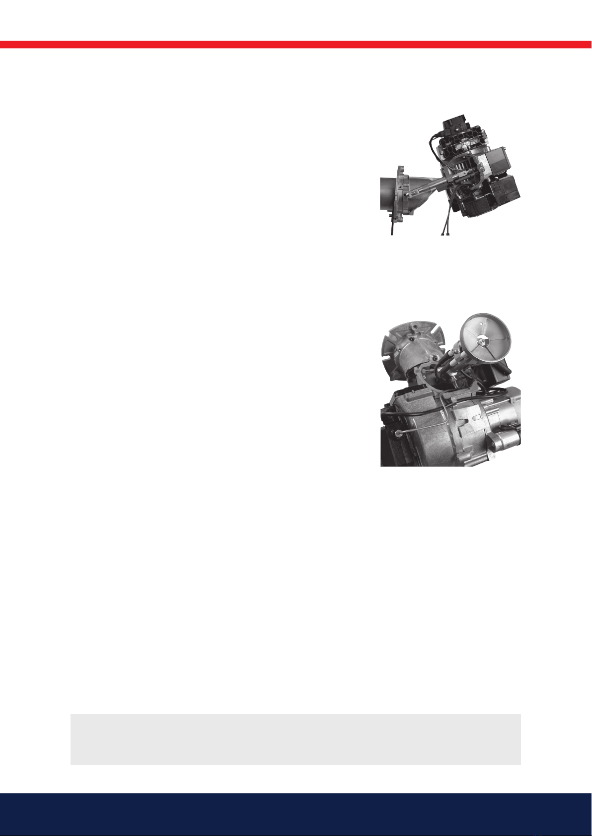
!When servicing or replacing components that affect combustion, analyses and
soot tests must be carried out on the installation.
5.1.1.3 Service position 3
1. Switch off the power at the main switch and disconnect the Eurostecker
from the burner.
2. Undo the screw which fastens the burner front piece to the fan
housing, but only so much as to allow the fan housing to be removed
from the burner front piece.
3. Remove the fan housing from the burner front piece and pull it
backwards until the combustion assembly is free of the burner front
piece.
4. Turn the screw into the front piece until there is a gap of approx. 5 mm
between the metal and the screw head.
5. Suspend the fan housing by the fan housing service attachment on the
screw used for joining the front piece to the fan housing, with the air
intake upwards, as shown in the illustration to the left.
5.1.2 Combustion assembly service
1. Switch off the power at the main switch and disconnect the Eurostecker
from the burner.
2. If so desired, service position 1 may be used.
3. Carry out a visual inspection of the combustion assembly and check
the various parts for defects.
4. Undo and remove the brake plate and the electrode package from the
oil pipe. Clean the brake plate as necessary.
5. Screw off the nozzle.
6. Install the nozzle. The nozzle may not be cleaned; it must be replaced
with a new nozzle if the existing one is considered defective.
7. Check the ignition electrodes. Replace as necessary (refer to Technical
data for electrode settings).
8. Install the brake plate and electrode package. Check that the distance
between the nozzle and brake plate is correct
(refer to Technical data).
9. Undo the screw that the fan housing is suspended from. Reassemble
the front piece and the fan housing and fasten them together.
10. Connect the Eurostecker and switch on the power at the main switch.
11. Start the burner and check the combustion.

20 Bentone
!When servicing or replacing components that affect combustion, analyses and
soot tests must be carried out on the installation.
5.1.3 Preheater replacement
1. Switch off the power at the main switch and disconnect the Eurostecker
from the burner.
2. If so desired, service position 1 may be used.
3. Remove the brake plate and electrode package.
4. Disconnect the preheater cable from the preheater.
5. Screw off the nozzle.
6. Undo the nut that connects the oil pipe to the preheater.
7. Install the new preheater. Check the condition of the O-ring; replace
as necessary.
8. Connect the preheater cable.
9. Install the nozzle.
10. Install the brake plate and electrode package. Check that the distance
between the nozzle and brake plate is correct
(refer to Technical data).
11. Re-assemble the burner.
12. Connect the Eurostecker and switch on the power at the main switch.
13. Start the burner and check the combustion.
Table of contents
Other Bentone Portable Generator manuals


