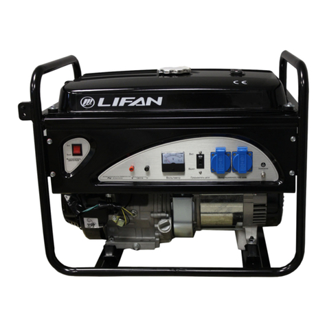
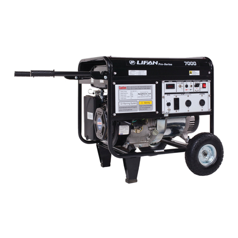
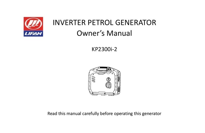
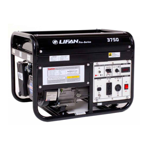
Lifan G2300i User manual

INVERTER GENERATOR
Owner's Manual
LF2300i-2
:É#- a
N@
@
Read this manual carefully before operating this generator
G2300i(2300W)

PREFACE
Thank you for choosing a gasoline generator set by our Co.
Based on the latest technology at home and abroad, our Co. has successfully developed the gasoline
generator set. The unit is chamcterized by advanced design, compact shuchrt'e, reliable performance, convenient
service, low fuel consumption and noise as well as fashion shape. With general gasoline engine as power, it is
widely used in many helds such as living, open working, shop, bank, fishing, etc.
The manual gives infonnation with respect to operation and rnaintenance of the gasoline generator', and be
sure to read it carefully first before operating. If any trouble occurs, call your dealer who will provide you with
the best after service.
All the materials and diagrams of this manual are in accordance in this manual may be a little different from
the actual states. The copyright of this manual belongs to our Co., any group or individual is forbidden to reprint
or copy any of it. The manual is subject to change without notice .
Safety Warningr ,
Please read this manual carefully before using this gasoline generator se@.
Special imporlant contents in this manual will be indicated in the following ways, please note.
M, If you do not follow the instructions, your life will be in danger or you will be seriously injured.
i!ffi: If you do not follow the instructions, your life will be in danger or you will be seriously injured
M,Fai1uretofo1lowinstructionsmayresu1tinminimalharm.
@, Failure to follow instructions may result in damage to your engine set and other properfy.
This specification is a permanent part of the gasoline generator set and should be attached when the gasoline
generator set is transferred to others.

COI',{TENTS
1. Safety notice for gasoline generator set "
2. Introduction to Parts and Components "'
3. Control function
3. lThree-in-one combination switch "
3.20rl alarm indicator light (red) " " "
3.3 Overload alarm indicator light(red)
3.4 AC indicator light(green)'
3.5DC protection'
3.6Energy-saving switch'
3 .TYoIfage recovery button ' ' ' '
3.8Fuel tank cap
3.9Fuel tank cap vent knob
3. l0Grounding (Earth) terminal" " " "
3. I I Parallel operation
4. Pre-use inspection
4.1 Fuel
4.2Bngine oil" "'
4.3Preparation'" "''
1
3
6
6
7
1
d
9
10
10
11
11
11
l2
13
13
l4
t6

5. The operating "'
5. I Start'
5.2Stop'
5.3AC connection'
5.4BatTery charging'
5.5AC parallel operation'
5 .6Scope of application " " "
6. Maintenance" " "
6. l Spark plug maintenance " " " " " "
6.2Adjustment of carburetor" " " " "'
6.3Replacement of engine oil " " " "'
6.4Air filter' '
6.5Mufi1er mesh and spark collector '
6.6 Fuel tank filter
6.7 Change of carburetor for highland
7. Storage' "':""""
B. Tloubleshooting'
9. Parameters"""'
10. Wiring diagram'
t7
l8
t9
20
2l
23
25
27
29
30
30
3l
32
JJ
JJ
34
36
39

1. Safety notice for gasoline generator set
1. Never operate it in an enclosed room. 2.Never connect to home circuit.
4.Keep the inflarnmables away from the
unit at least one meter.
7
3.Do not operate it under wet circumstances.

5. No smoking when filling fuel. 6. Always frll fuel after stopping it.
7. Do not spill out when filling ftiel.
2

Affi
When connecting the generator to home power suppll', make sure itls done by a skilled electrician.
Improper connecting betrveen the generator and loads may cause damage, burn or fire to the generator.
1. Correct
L. Correct
3
3. Forbidden

2.Introduction to Parts and Components
O Sparl< plug maintenance cover
@ Fuel tank cap vent knob
@ Fueltankcap
@ Canying handle
@ Controlpanel
@ Starting handle
@ Rear blinds3-in-1 switch knob (engine starler
button, fuel switch and choke switch)
@ Spark plug maintenance cover
@ Rear blinds
@ Muffler assembly
@ Oit porr baffle
4

2.lControl panel
l20Y 60Hz
C Vottage recovery button
@ Oit alarm indicator light (red)
@ Overload alarm indicator light (red)
@ AC indicator light (green)
@ e.C socket
@ Energy saving switch (ESC)
@ OC socket
@ uSs socket
@ nC protection
@ Parallel socket
@ Grounding (earth) terminal
o
(D
::.1
(D
oo
it :il
5

230V 50Hz
!èJ 0iù
^
lt
C aC socket
@ Oit alarm indicator light (red)
@ Overload alarm indicator light (red)
@ aC indicator light (green)
@ Voltage recovery button
@ Energy saving switch (ESC)
@ OC protection
@ lC socket
@ usn socket
@ Parallel socket
@ Grounding (earth) terminal
6

3.Control function
3. I Three-in-one combination switch
0
ffiso @
@
C Engine and fuel switch in "OFF" position:The ignition
circuit is closed, the fuel switch is offand the engine cannot start.
@ Engine, fuel switch and choke switch in "ON" position:The
ignition line is in working state, fuel switch is opened, choke is in
fuIl open state and the engine can operate normally.
@ Engine, fuel switch and choke switch in "CHOKE" position:
The ignition line in the state of work, fuel switch is on, choke is in a
closed state and the engine can starl normally.
NOTICE: When the engine is hot, it does not nced to rotate to the "CHOKE" position when starting.
7

ÛVSNLÛA} ÂC
3.2Oil alarm indicator (red)
When the crankcase oil droppçd below the safety line, the oil
protection system will automatically shut offthe engine and the oil
alarm indicator light wilt light up. Filling the oil to the oillevel, the
engine will start again.
NOTICE: If the engine stalls or fails to start, rotate the power switch lmob to the "ON" position, then pull
the start handle. If the oil alarm indicator light flashes for a few seconds, the oil is insufficient. Fill in the oil
and restarl..
3.3Overload alarm indicator light(red)
When the overload indicator lights up, it's detected that the output of the
connected loads has been overloaded, causing the converter to overheat. At
this time, the AC protector works and it makesthe generator stop working to
protect the generator and the connected electrical equipment. When the AC
indicator light (green) is offand the overload indicator light (red) is on, the
generator will not stop working
When the overload indicator is on and the unit has no output, the following measures should be taken
i. Close and remove the connected electrical equipment.
2. Reduce the total power of the connected electrical equipment to the rated output range.
ô
t7 in
itu

3. Check whether there is a foreign body blocking the air inlet and whether there is any abnormality in the
relevant control parts. If there is any problem, immediately eliminate it.
4. After check. press the voltage recovery button for 1-3 seconds to restôie the voltage output.
NOTICE: When using electrical equipment with high startup current (such as Çompressors, submersible
pumps, etc.), the overload indicator may light up for a few seconds at the beginning.However this may not be
the fault mentioned above. Overload, short circuit, overheating and low engine speed, all of them can stop the
output. Elimrnate the above reasons tillthe output is restored.
3.4 AC i ndicator light(green)
When the engine starts and outputs normally, the AC indicator lights up
Indicator judgment:
1. Green light on: indicating normal operation, generator output;
2. Green light on and red light flashing: indicating overload, generator output;
3. When the green light is off and the red light flashes once every 3 seconds: indicating that the bus fi-ont-end
voltage is too low and the generator has no output.
4. When the green light is offand the red light flashes fwice in 3 seconds:indicating that the engine speed is too
9
AU
TI ÛVEItLOAil

low and the generator has no output.
5. When the green light is offand the red light flashes three times in three seconds: indicating that the temperature
ofthe inverter is too high and the generator has no output. a:
6. When the green light is off and the red light flashes 5 times in 3 seconds: indicating that the bus voltage is too
high and the generator has no output.
7. The green light is off and the red light flashes 6 times in 3 seconds: indicating overload protection and no
ouFput.
3.5DC protection
When the electronic equipment connected to the generator is running, if the rated current
is exceeded, the dc switch will automatically turn to the "OFF" position. Press the DC
switch to the "ON" position if you want to operate the generator again.
"ON": Normal DC output
"OFF":No DC output.
NOTICE:
If DC protection is ofl reduce the load of the connected electronic equipment to the rated output range of the
generator. If DC protection is still off, stop using electrical equipment directly and consult the dealer.
10

tii
3.6Energy-saving switch
O "ON", when the energy saving switch is in the "ON" position, the energy saving
device controls the engine speed according tcr-the connected loacl, which can achieve
better fuel consumption and lower noise.
@ "OFF", when the energy-saving switch is in the "OFF" position, the engine is
running at the rated speed (3600r/min) regardless of whether the loacl is connected.
NOTICE: When using the following equipment, such as air compressor, sunk water
pump, the enelgy-saving switch must be shut offdue to the need for a large startup current.
3.TVoltage recovery button
When the generator ovelload light is on, the generator has no voltage output, but still
working, check and remove all the loads and press the voltage recovery button for 1-3
sec to restore the voltage output.
NOTICE:When the ovsrload voltage recovers, please ensure that there is no load
connection, no short circuit and other faults before pressing the recovery voltage button.
t
t
$
{
Ë"-n
F"
$
m
3.8Fuel tank cap
71,

Rotate counterclockwise and remove the tank cap.
There is a vent knob on the top of the fuel tank to stop the flow of fuel. When using the
generator, the vent knob must be in the "ON" position so that fuel can be injected into
the carburetor to keep the engine running. When the generator is not in use, turn the
ventilation lcrob to the "OFF" position to stop the flow of fuel.
3.9Fuel tank cap vent knob
3.l.0Grounding (Earth) terminal
When connecting the grounding terminal to the grounding wire, be cautious of the
electric shock. If the electrical equipment is grounded, the generator must be grounded.
3.1lParaltel operation
t2

*--v.::
The parallel connector is used to connect two paralleling special cables of two same voltage
and frequency devices of 2300i-2. Parallel operation requires |wo 2300i-2 devices and
special cables.(Rated output power of parallel operation is 3.4KVA, rated current of 120V
generator is 28.0A and rated cunent of 230V generator is 14.5A)
Operating procedures and related considerations are detailed in the parallel output system.
IJ

4. Pre-use inspection
NOTICE: Be snre to check before each use.
4.1Fuel
WARNING: The engine and mufflerwill become very hot after itworts. Do not check and repair them
before they are cooling.Avoid any part of your body and clothes contact with the engine and
muffler.
DANGER: The fuel is a kind of flammable poison. Read carefully before refueling safety requirements (see
page 2 for details).Don't fill up too much, or the tank will overflow when it walms up.After refueling, make sure
the cap is screwed tightly.
NOTICE: After refueling, wipe the residual gasoline with a clean and soft cloth in time to avoid damage to the
plastic shell.Unleaded gasoline must be used. Leaded gasoline can seriously damage engine intemal parts.
Remove the fuel tank cap and add gasoline to the shoulder of the fuel filter.
O Rea indicator bit;
@ Fuel level.
Recommended fuel: unleaded gasoline
Fuel tank capacity: 4L (1.06 us gallons,
0.88 UK gallons)
1.4

4.2Engine oil
This generator is delivered r.vithout oil injection. Do not start the engine until sufficient oil has been injected.
1. Please place the engine on a horizontal plane. i-
2.Rotate the locking handle of the oil port baffle and remove the oil port guard@.
3. Turn on the dipstick@.
4. Inject the specified amount of recommended oil and tighten the dipstick@
5. Install back the outer guard platee.
Recommended oil: SAE SJ 10w40
Recommended oil grade:API standard SE or higher'
Oil capacity: 0.35L
ô
15
Table of contents
Other Lifan Portable Generator manuals

Lifan
Lifan ES1500 Assembly instructions

Lifan
Lifan G1800 User manual

Lifan
Lifan KP4500iE User manual

Lifan
Lifan ESI3600iER Assembly instructions

Lifan
Lifan LF3750 Assembly instructions

Lifan
Lifan 7000 Pro series User manual

Lifan
Lifan G12500E User manual

Lifan
Lifan KP2300i-2 User manual

Lifan
Lifan 2.8GF-3/4 User manual

Lifan
Lifan PRO Series Assembly instructions
Popular Portable Generator manuals by other brands

Champion Power Equipment
Champion Power Equipment 73536i Owner's manual & operating instructions

Fluke
Fluke 291 user manual

Champion
Champion 42451 Owner's manual & operating instructions

Champion
Champion 73537i Owner's manual & operating instructions

Bluetti
Bluetti AC200MAX user manual

iPower
iPower SC2000I owner's manual