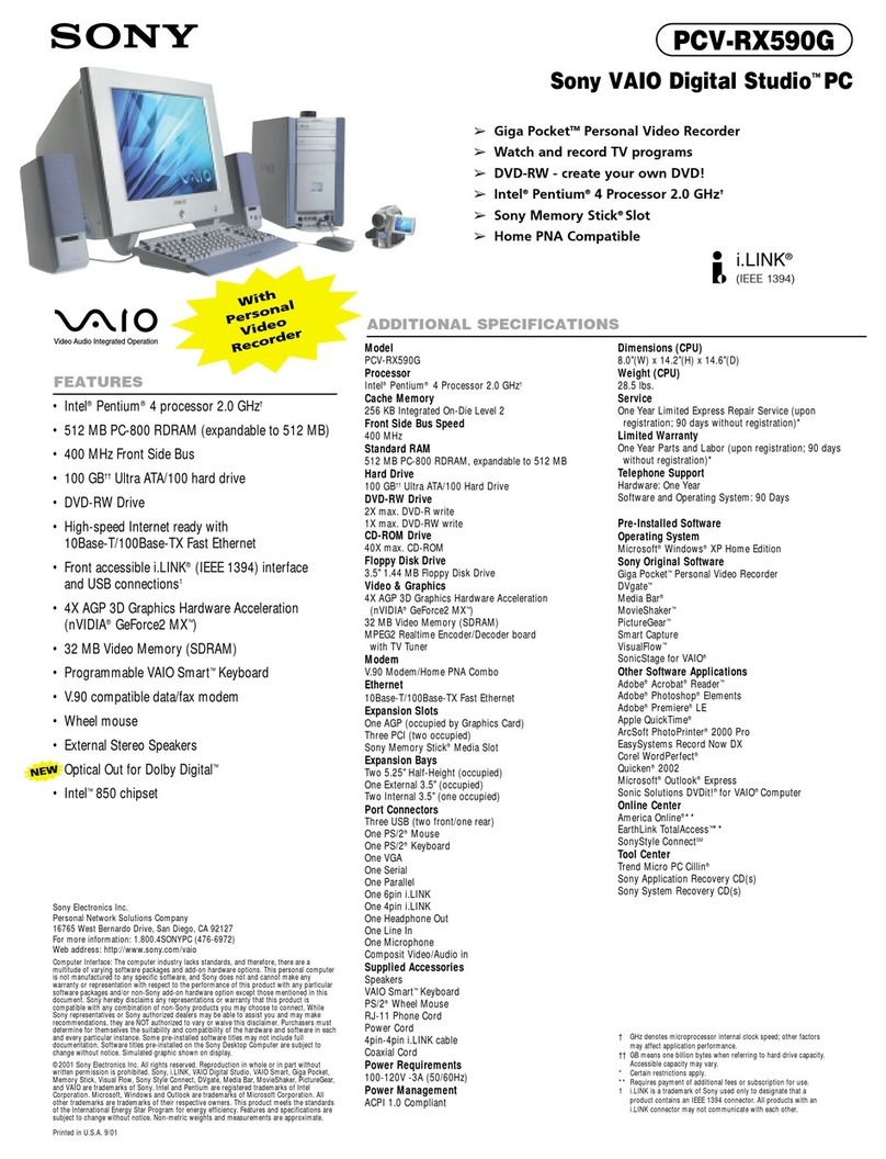
bentrup TC 505 User manual

TC 505
21
546
879
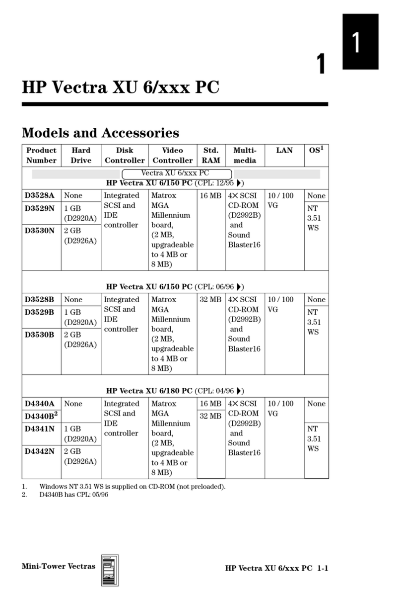
30
start
stop
event 1
event 2
hold
shift select
t2
t1
t0
prog
memo 1050°C 1180°C 1250°C
150°C 800°C 900°C
rmp3
rmp1 rmp2
tmp2
tmp1
°C/h
h.min
°C
°F/h
°F
Z3
Z
1
Z2
THERMOCOMPUTER
TC 505
Operating Instructions

2
prog
1
event 1
start
stop
memo
0
hold
(about 3 seconds)
21
546
879
30
start
stop
event 1
event 2
hold
shift select
t2
t1
t0
prog
memo 1050°C 1180°C 1250°C
150°C 800°C 900°C
rmp3
rmp1 rmp2
tmp2
tmp1
°C/h
h.min
°C
°F/h
°F
Z3
Z
1
Z2
THERMOCOMPUTER
TC 505
1
3
9
8
4
10
21
20
19
12
15
2
5
11
14
13
6
7
16
17
18
9
5
Brief Instructions
start a programme (e.g. no. 15)
save the current firing curve as a programme
(e.g. no. 9)
to lock the controller
use this key
Controllers Panel 1zone # currently displayed
2indicator„controller keypad locked“
3 read / change final firing temperature
4 read / change 1st dwell temperature
5 read / change programme delay
6 read / change 1st heat up ramp
7 read / change 1st dwell time
8calling up a programme
9saving a programme
10 key to lock the controllers keypad
11 shift key
12 display for kiln temperatures etc.
13 unit of the process of programme
value displayed in (12)
14 process value or programm value
on entering programmes
15 grafical scheme of the firing curve
16 read / change cooling ramp
17 read / change dwell time
18 read / change 2nd heatup up ramp
19 keypad for entering values
20 key to start and to stop a firing
21 calling up additional values displayed
in (12) and entering configuration

Your TC505 is the choice of the professionals in the
bentrup controller family TC500. These controllers
use the latest technology available and incorporate
many features which haven´t been available on kiln
controls before. Appearing as a controller easy to use,
it is a highly sophisticated instrument with a totally
configurable control design allowing adaption to
almost all applications (for details see Appendix C).
Reading through this manual quickly familiarizes you
with the numerous features of the TC505.
Please also refer to the safety advise of your kiln
manufacturer. Make sure that the control is placed at a
proper distance from the kiln and is not exposed to
direct heat or radiation from the kiln.
3
General Information.............................................3
Calling up a Programme.......................................5
Starting a Firing ...............................................5
Displays during a Firing...................................6
Entering and Checking a Firing Curve...................7
The Value SKIP................................................7
Starting a Programme...........................................8
Working with Programmes ..............................8
Reading the Kiln Temperature ..............................9
Control outputs, Time / Date............................9
Locking the Controller........................................11
Miscellaneous
Power Failure.................................................11
Actual Duration of a Segment........................11
Kiln can not follow the Ramp........................11
Miscellaneous ...............................................12
Appendix A: Error Messages of the TC505..........13
Appendix B: Data- and Error Log........................16
Calling up the Data Log.................................17
Calling up the Error Log.................................18
Appendix C: Configuration.................................19
Explanation of the Parameters........................20
Calling up the Configuration..........................22
Appendix D: Weekly Switching Clock ................23
Appendix E: Communication Link ......................24
Appendix F: Checking Installed Options.............24
Appendix G: Electrical Connections...................25
Contents
General Information

The microprocessor controller TC505 allows an exact
and reproduceable control of your kiln. The sketch
below shows a firing curve of the TC505. Each firing
curve consists of the segments (a) to (f). Example:
programme delay (a):
The controller waits for the time set before the actual
firing is started. This can be used to take advantage of
off peak electricity. In the example no programme
delay is entered.
heating up to 1st dwell (b):
The kiln heats up at the set rate. The rate is entered as
degrees centigrade per hour (you can confi-gure to
enter as time of you prefer, see appendix C).
1st dwell at set time and temperature (c):
After reaching the temperature the kiln remains for set
time. The time is entered as hours / minutes.
heating up to 2nd dwell (d):
The kiln heats up at the set rate to the firing
temperature. The example shows SKIP which stands
for heating at maximum power (ie. uncontrolled).
dwell at final temperature (e):
The kiln temperature remains at the final temperature
for the set time this may be that all fired goods are
entirely heated through.
cooling or programme end (f):
After completing the dwell the kiln is cooled either
controlled (e.g. 200°C/h) or uncontrolled (SKIP) as
shown in the example. The TC505 finishes control in
this cooling ramp at 150°C showing „End“ in display
(14) for successful completion.
4
1050
Temp
(°C)
400
f
200°C/h
SKIP
SKIP
0.00h
0:10h
0:15h
Segment
0:00h
2:00h
edabc
150
t0
rmp1
t1
rmp2
t2
rmp3

You can save up to 29 firing curves in your TC505 as
programmes. The programme numbers 1 to 6 are
factory set and cannot be altered. Please find the
values of these 6 programmes below:
The following example demonstrates how to call up
programme number 04 and to start the firing:
After turning on the TC505 display (14) is empty.
Pressing key (8) the controller display appears as
shown on the left.
Now enter „0“ and „4“ on the keypad (19). Note that
the programme number must always be entered as a 2
digit number. The TC505 prompts entering a valid
programme number by showing the maximum tempe-
rature of the selected programme on display (14).
Press key (20) to start the firing. From now on the
current segment of the firing lights up in the firing
curve (15). Display (14) reads the current setpoint,
display (12) the temperature inside the kiln.
5
Calling up a Programme
°C/h
h.min
°C
°F/h
°F
t2
t1
t0rmp3
rmp1 rmp2
tmp2
tmp1
°C/h
h.min
°C
°F/h
°F
prog # t0 (min) rmp1(°C/h) tmp.1 (°C) t1(min) rmp2(°C/h) tmp.2 (°C) t2(min) rmp3 (°C/h)
01 0 30 150 10 skip 150 10 skip
02 0 100 600 0 skip 800 10 skip
03 0 100 550 0 skip 900 10 skip
04 0 180 400 0 skip 1050 30 skip
05 0 180 400 0 skip 1180 30 skip
06 0 180 400 0 skip 1250 30 skip
°C/h
h.min
°C
°F/h
°F
prog
0
hold
4
1050°C
Note
The flashing decimal point on the right hand side of
display (12) always indicates a running programme.
If a programme value (rather than a setpoint) is
shown in display (14) the corresponding section of
firing curve (15) is flashing.
start
stop
Starting a Firing
Z3
Z
1
Z2
flashing

By default during a firing the current programme
setpoint is shown on display (14). On heat up ramps
this setpoint counts upwards according to the
programmed rate. Every 15 seconds display (14)
flashes the maximum temperature of the currently
selected firing. This allows you to double check the
most important value of the firing without pressing
any keys.
Pressing key (11) followed by key (21) changes the
display (14) to the remaining time in the current
segment. On ramps the estimated time is calculated
whilst on dwells the entered time counts backwards.
In general the reading shows hours / minutes; if the
time is less than 1 hour the indication is in minutes /
seconds (unit display (13) „h.min“ is blinking).
After 15 seconds or when pressing key (10) followed
by key (20) again the the display (14) switches back to
the programme setpoint.
During a programme delay always the remaining time
until the programme starts is always shown.
Watching the firing curve (15) allows you to see how
your TC505 processes the firing curve segment by
segment. The programme is completed if the kiln
temperature reaches 150°C in the cooling segment (f).
„End“ on display (14) comfirms successful completion
of the firing process (as depicted on the left).
6
Displays during the Firing
t2
t1
t0rmp3
rmp1 rmp2
tmp2
tmp1
°C/h
h.min
°C
°F/h
°F
t2
t1
t0rmp3
rmp1 rmp2
tmp2
tmp1
°C/h
h.min
°C
°F/h
°F
shift
select
tmp2
tmp1
°C/h
h.min
°C
°F/h
°F
blinking

7
You can check the values of a firing curve at anytime
even during programme run. If you want to change a
value you have to stop the firing by pressing the key
(20).
For instance to check the heat up ramp press key (6).
Display (14) reads the current value for the heat up
speed. The unit of the value (in this example degree
centrigrade per hour) is shown in (13). The correspon-
ding segment (b) of the firing curve (15) lights up.
To change this value simply enter a new value by
using the keypad (19). If you enter a value that is
outside the allowed range the controller rejects by
showing „- - - -“. If this is the case simply enter the
correct value.
For instance to check the final temperature press key
(3). As described before, the current value is shown in
display (14) and the corresponding section (d) of the
firing curve (15) lights up.
To change this value proceed as described before.
All values of the firing curve can be checked and - if
required - changed as described. The sequence of
checking or changing is free. Only keep in mind always
stop a firing if you intend to change a programme.
On delays of more than 15 seconds the display (14)
returns to the current programme setpoint. Select the
segment to change again if you wish.
On most firings the customer wants to heat up the kiln
as fast as possible from 1st dwell temperature to final
temperature. This is done by entering the value „SKIP“
on segment (d).
Press key (18) to select segment (d). Now press the
digit key „9“ on the keypad (19) 4 times. TC505
shows „SKIP“ on display (14) as depicted on the left.
This option can be used on all ramps (i.e. segments
(b), (d) and (f).
The Value SKIP
9
Entering and Checking a
Firing Curve
t2
t1
t0rmp3
rmp1 rmp2
tmp2
tmp1
°C/h
h.min
°C
°F/h
°F
t2
t1
t0rmp3
rmp1 rmp2
tmp2
tmp1
°C/h
h.min
°C
°F/h
°F
rmp1
tmp2
t2
t1
t0rmp3
rmp1 rmp2
tmp2
tmp1
°C/h
h.min
°C
°F/h
°F
9
9
9
rmp2

8
You can save up to 29 programmes in your TC505.
Once a firing curve has been saved as a programme it
can be called up easily to be modified, saved again or
simply used by starting the firing.
To save a firing curve that has been entered before as
e.g. programme number 25 proceed with the
following
steps: Press key (8). The display (14) asks for the
programme number as shown on the left („programme
save“). Now enter the programme number „25“.
Please note that a programme number must always be
entered as a two digit number (e.g. „0“ and „9“ for
programme no 9).
After successfully saving the current firing curve the
display (14) reads the final temperature of the
programme (or the current firing). If the display shows
„PS.- -“ you have tried to enter an invalid programme
number which has been rejected by the controller.
The first 6 programmes are factory set and cannot be
changed. This ensures that you always have a set of 6
standard firing curves available. The values of these
programme number 1 to 6 were listet on page no. 5.
The programmes number 7 to 29 can be set according
to your requirements as described previously. You can
change and update them as often as you wish.
Presuming you frequently need a firing curve which is
the same as preset programme no. 5 but with a final
temperature of 1195°C and 20 minutes dwell. This
programme is to be saved as no. 15.
Call up programme no. 5 and change the final tempe-
rature (1195°C) and dwell (20 min). Now save the
firing curve as programme no. 15.
Note
The progamme number must always be entered as a 2
digit number
.
Example: Enter „05“ for programme no. 5
t2
t1
t0rmp3
rmp1 rmp2
tmp2
tmp1
°C/h
h.min
°C
°F/h
°F
Saving Programmes
Working with
Programmes
memo
2
event 2
5
prog
0
hold
5
tmp2
1
event 1
1
event 1
9
5
t2
2
event 2
0
hold
memo
1
event 1
5

9
Display (12) shows continuously all values of the
current process such as actual kiln temperature,
heating power (in %), status of the control outputs etc.
All values are shown in sequence by pressing key (21).
The TC505 is available in a version for multizone
kilns. The indicator (1) points to the zone the value
refers to. For details about multizone kilns please
check out the „Technical Manual TC500 Series
Controller“ available on http://www.bentrup.de.
The sequence of the process values can be determined
in the configuration. By default the values shown in
display (12) by pressing key (21) are as follows:
Actual Kiln Temperature
The actual temperature of the kiln is shown. On
multizone kilns the temperatures are shown zone by
zone pressing key (21). Zone no# refer to indicator (1).
„over“: no sensor (thermocouple) connected, sensor broken,
sensor wiring broken or adjusted sensor temperature exceeded
„under“: sensor or wiring polarized bad. On switching poles
check color codes ! A wiring switched at both ends (!) can NOT
be determined by the controller and will cause overfiring !
„invalid“: signal acquisition bad, error on determining cold
junction temperature or controllers data acquisition defect.
Actual kiln heating in percent
On kilns switching ON / OFF only the percentage is
represented by the on/off duty (e.g. 50% means 15
seconds on and 15 seconds off).
„channel off“: currently no control process, for instance during
programme delay or programme not started.
„channel over“: control channel has been switched off due to
error of corresponding signal input (e.g. „over“ on input).
Automatic reset when starting a programme.
„channel gradient error“: For safety reasons TC505 checks the
temperature increase of the kiln during full power heating. When
dropping below 3°C per 15min this error message appears.
Typical
causes:
heating elements too old or broken, one phase of mains
supply missing or missing by contactor failure, short circuit of
thermocouple or wiring.
Not a defect of the controller !
Z3
Z
1
Z2
Z3
Z
1
Z2
Z3
Z
1
Z2
Z3
Z
1
Z2
Z3
Z
1
Z2
Z3
Z
1
Z2
Z3
Z
1
Z2
Z3
Z
1
Z2
Displaying the
Kiln Temperature

status of the control outputs
Any activated outputs are shown by their number
(example shows all 4 outputs active). The function of
an output is determined by the configuration.
process errors
Any process errors during the firing. On the left hand
side an „E“ is shown followed by an error code if
applies (example shows code „A4“). Refer to appendix
A for a complete listing and explanation of all errors.
Power consumption since programme start
Displays the total power consumption since last
programme start. The TC505 calculates this value by
adding up the heating cycles. Make sure that the kiln
power rating is properly set in the configuration (see
appendix C, parameter 1).
Operation time of the heating elements
The TC505 adds up the net operation times of the
heating elements (ie. only the duration where they
were actually under power) since programme start.
This allows you to check the load of the kiln or the
efficiency of the heating elements.
Total operation time of heating elements
As before but time is added up to a total value to
check lifetime of the heating elements. Very useful
feature to proove warranty claims as well as getting an
impression about how intensive a kiln has been used.
For safety reasons reset to zero only by manufacturer.
Realtime clock display: day of week and time
Your TC505 is also available with a real time clock
(optional, can be installed at anytime) for automatic
commencing programmes. If your TC505 is fitted with
this option this display is shown to check current day
of week and time (hours / minutes).
10
Z3
Z
1
Z2
Z3
Z
1
Z2
Z3
Z
1
Z2
Z3
Z
1
Z2
Z3
Z
1
Z2
Z3
Z
1
Z2

The prevent the TC505 from unauthorized usage you
can lock the keypad by pressing the key (10) for about
3 seconds. The indicator (2) shows the TC505 is now
locked. If the controller is locked you can for instance
only call up values but not start or interrupt a firing.
To unlock the controller press and hold key (10) again
until the indicator (2) goes off.
In case of a power breakdown the firing process is
interrupted. After power is established again the firing
process is continued from that point at which it was
interrupted. If the kiln temperature has dropped more
than 50°C since the power failure happened the firing
is interrupted (an error messages comes up - see
appendix A).
In theory a ramp takes exactly the time which is
programmed. However, if at the beginning of a ramp
the actual kiln is higher than the initial ramp tem-
perature the time is adjusted accordingly. Example:
Ramp in 2 hours up to 500°C. If the kiln is already at
250°C the time is set to 1 hour only. This also ensures
that the setpoint starts at the kiln temperature. The
ramp is finished when the time has elapsed.
What happens if the kiln temperature is unable to
keep up with the programmed temperature increase?
Example: Ramp asks in 1 hour to 1000°C. Your TC505
handles this situation as best as possible (only if para-
meter #9 is set to 0 or 1): When the heating power
reaches 100% (and therefore there is no control any
more) the ramp time (or setpoint) is held (display (14)
flashes „hold“). When the kiln temperature has caught
up the time continues automatically.
To avoid a firing process locking itself because of lack
of kiln power in a ramp an automatic continuation is
performed.
By using the function „hold“ you can also manually
release the ramp „hold“ (press shift + key 0, see
below).
11
Power Failure
Locking the Controller
Actual Duration of a
Segment
Kiln can not follow
the Ramp

On uncontrolled ramps the TC505 stays in the segment
until the final temperature is reached. On multizone
kilns the TC505 waits for all zones. To avoid the
process locking itself because of heat-shift between
the zones, there is a complex algorithm which realizes
this situation and causes a step to the next segment.
On severe errors (like a broken sensor etc.) the TC505
interrupts the process and shows an error message.
The TC505 provides you with the feature to hold the
process manually. Press key (11) followed by the digit
key „0“ (hold). Display (14) shows flashing „hold“ and
the firing process is held until the key (11) followd by
key „0“ is pressed again.
A „hold“ causes the programme to remain at the
setpoint in a controlled (!) ramp by holding the time.
In a dwell the time is also held infinitely.
Your TC505 provides you with the option of entering
the heating and cooling ramps as time (hours /
minutes) rather then degrees centigrade per hour
(°C/h). Some people are still more used to these values
although they are a leftover from controllers used in
the past. Your ceramic is interested in the temperature
gradient and not in the time required for it !
In the example given on page 4 enter 2 hours (instead
of 200°C/h) in segment (b). Enter a time of „0.00“ to
programme uncontrolled heating / cooling (SKIP).
Appendix C explains how to change the controllers
configuration (set parameter 11 to „time“).
12
Hold Process
Interruption of the
firing on Errors
shift
0
hold
t2
t1
t0rmp3
rmp1 rmp2
tmp2
tmp1
°C/h
h.min
°C
°F/h
°F
Heating / Cooling
Segments entered
as Time
rmp1
t2
t1
t0rmp3
rmp1 rmp2
tmp2
tmp1
°C/h
h.min
°C
°F/h
°F
Uncontrolled Ramps
(SKIP)

13
error on sensor input
The control channel shuts down because of an error
on the sensor input (e.g. overflow). Error is latched
until next firing is started. Possible causes:
• thermocouple or compensating wire interrupted
• maximum temperature has been exceeded
• thermocouple polarized wrong (temperature reading
„under“)
policeman activated
When exceeding the maximum programme tempera-
ture by 20°C or more the integrated policeman shuts
down the kiln using the safety contactor (applies only
if your kiln is fitted with a safety contactor). This
prevents your kiln from overfiring in case the main
contactor stucks in the ON position for instance.
Possible causes for over temperature:
• kiln contactor stuck in ON position
• a contact of the contactor has melted together
Certain errors (like power breakdown, break of sensor,
kiln problem etc.) found by the controller are
processed accordingly. Important errors are show
immediately on display (12) by a unique code number
(see example on the left hand side showing code
„A4“). All error messages are recorded by the
controller for post analyzation (see appendix B).
The error codes are divided into operation or control
problems (codes A ..), power breakdown (code B ..),
internal problems (code C ..) and hardware problems
(code D ..).
Following is a complete listing and explanation of all
possible error messages:
Z3
Z
1
Z2
Error A1
Error A3
Appendix A
Error Messages
of the TC505

14
temperature increase on full power too low
The error message clearly points out a problem of the
kiln. Possible causes:
• mains fuse / phase broken, heating elements broken
• heating elements too old (on high temperatures)
• short circuit on thermocouple or compensating wire
• contactor broken
(check after operating for some time !)
kiln does not follow programmed temperature increase
Other then error 4 bad programme values are the
cause for this message. Firing is not interrupted !
Message comes up only if enabled in the
configuration (appendix C, parameter 9).
ramp has been continued automatically
If the temperature increase does not follow the
programme the ramp is held on (see section „Kiln can
not follow the Ramp“). If the controllers finds the kiln
unable to catch up with the temperature the firing is
continued and this message is shown for 1 minute.
SKIP ramp has been interrupted
In an uncontrolled ramp the controller tries to match
all zone temperatures to the requested final value. If
the controller found the kiln unable to achieve this it
continues to the next section. In this case the error
message A9 is shown for 1 minute to inform the user.
firing process after power breakdown continued
After re-establishing power supply the firing process
has been continued.
Error A4
Error A5
Error A8
Error A9
Error B2

15
firing process interrupted after power breakdown
After re establishing power supply the firing process
has been interrupted due to e.g. kiln temperature has
dropped too much. If there is a digit shown after the
comma it gives further information about the cause
(e.g. B3.4 = temperature dropped too much).
If this error message comes up right after turning on
the controller by the mains switch you can disregard.
It just means that the controller has been turned off
last time when the firing had not been totally completed.
Simply continue working by entering a programme.
internal problem
Technical assistance required (C1 signal acquisition
broken, C2 signal acqusition not within precision
limits, C3 systembus communication error, C4
systembus configuration setup mismatch).
hardware error
Technical assistance required (D1 processor fault, D2
RAM error, D3 bus error, D4 configuration memory
error, D5 calibration data invalid).
Error B3
Error C1, C2
C3, C4
Error D1, D2
D3, D4, D5

16
IYour controller TC505 is fitted with a data and error
log. All data and errors of the entire firing are
recorded continuously by the TC505. Such features
have not been known on this type of controller until
now! Don´t waste time watching a firing to discover
an error (and of course miss the most important
moment anyway !)
The data log records all important process values (kiln
temperature(s), setpoint, control outputs, times) once a
minute. The data log holds the last 36 hours which
can be inspected by the user. The recording takes
place automatically in the background (no matter
whether a firing is started or not). After turning off the
controller all data is lost.
The error log records values only if certain errors
happen (for instance all errors decribed in Appendix
A). The last 50 errors are recorded (including all
details (temperatures etc.) like in the data log). This
allows quick and efficient error tracking and trouble
shooting. The error log is permanent so it is not lost
when turning off the controller.
Data log as well as error log record the same set of
process data. These are the actual kiln temperature
and kiln heating (on multizone kilns from all zones),
the setpoint temperature, remaining time in segment,
segment number, status of the control outputs as well
as process information.
If your controller is fitted with the optional real time
clock the date / time when the data or error took place
is also recorded. This allows finding the error of
interest quickly and enables efficient reconstruction of
the problem.
Appendix B
Data- and Error Log
Data Log
Error Log

17
To view the data logged since last power up proceed
as follows: Press key shift (11) followed by memo (9).
This can be done at anytime also during programme
run without interrupting the programme.
Display (12) reads „L“ (for „Log“) followed by the log
number. All other displays show the same value as in
normal operation (i.e. setpoint temperature, segment
number etc.). As well all other process values can be
displayed pressing key select (21). Calling up the
remaining time instead of setpoint temperature using
the keys shift (11) followed by select (21) can be done
the same way as in normal operation display.
Additionally the time and date (only if TC505 is fitted
with the real time clock, see appendix D; if not
display of elapsed time since last power up) is
displayed (see example display on the left hand side).
To indicate log display other than normal operation
display a programme run is shown as a continuously
(and not blinking) decimal point in display (12).
To call up the further values which have been recor-
ded minute by minute the digit keys „0“ to „3“ are
misused. Press key „2“ to show next recording, press
„3“ to step back to previous recording. Keeping the
key pressed to step through the logs automatically.
Pressing key „0“ shows the 1st, „3“ the last record.
After 15 seconds without pressing any keys the display
changes back to normal and the current value are
shown. Alternatively press keys shift (11) followed by
memo (9) to return to normal display.
Note
The controller records the set of values every 60
seconds. If there is for instance a short switching in
between two recordings it can not be seen in the
data log of course.
Z3
Z
1
Z2
tmp2
tmp1
°C/h
h.min
°C
°F/h
°F
Z3
Z
1
Z2
tmp2
tmp1
°C/h
h.min
°C
°F/h
°F
2130
Calling up the
Data Log

18
To call up the error log press key shift (11) followed
by key prog (8). This can be done at anytime without
interrupting the programme.
Display (12) shows „E“ (stands for „Error“) followed by
the error #. You can read out about the last 50 errors.
The kind of display, the apperance, the options to call
up the values etc. are absolutely identical as described
before for the data log.
The error log records in seqence all previous errors.
The log can only be purged by the manufacturer and
is very efficient and essential to track up problems in
kiln or controller.
If the error log is empty the display reads „- -“ (see
display shown on the left hand side). This applies to
an empty data log as well.
Z3
Z
1
Z2
Z3
Z
1
Z2
Calling up the
Error Log
Note
The error that happened last (and so the most current
error) has the lowest number and is shown first

19
Because your TC505 can be used in a wide range of
applications some operating parameters of the
controller are adjustable. Usually if there were any
adjustments required they already have been done by
your supplier. Please refer to following parameter list If
you are interested in details:
Failure in setting up the parameter might easily cause
damage to kiln and firing goods. It is the users
responsibility to decide whether the changes made
are proper and safe. If you are in doubt do not adjust
the parameters !
Some adjustments are blocked for safety reasons (e.g.
changing the type of thermocouple from S/R to J/K or
vice versa).
Warning !
Appendix C
Configuration
par.-no. description default unit
1 power of kiln 0,0 kWh
2 < reserved > 0 cm/h
3 type of thermocouple (S, R, K, J) -
4 maximum temperature of the kiln 1320 °C
5 proportionalband 2.0 %
6 integral time 200 s
7 derivative time 10 s
8 cyclus time (or hysteresis resp., 1.0°C) 30 s
9 reaction on heat up problems 1 -
10 number of kiln zones 1 -
11 enter ramps as gradient (°C/h) or time (h.min) grad grad/time
12 function of the 1st additional control output 1 -
<13> function of the 2nd additional control output 0 -
<14> function of the 3rd additional control output 0 -

20
Explanation of the parameters (see # in brackets for parameter number)
power rating (1)
Power rating of the kiln. This value is only used for calculating the power consumption.
thermocouple code (3)
Type of thermocouple:
S=PtRh10%-Pt, R=PtRh13%-Pt, K=NiCr-Ni, J=FeCu-Ni. Change from S/R to
J/K and vice versa are locked for safety and technical reasons
.
maximum temperature of the kiln (4)
maximum adjustable temperature. Please make sure that this limit never exceeds the maximum
temperature allowed for the kiln !
proportional band (5), integral time (6), derivative time (7)
These so called control parameters adapt the controller to the heating characteristics of the kiln.
The default parameters ensure excellent results since they are continuously adapted by the
permanent auto tune feature of the controller.
cycle time (8)
Determines the number of switching cycles of the contactor. Frequent switching reduces lifetime
of the controller. On the other hand long switching cycles cause unsteady heating of the kiln. The
default value of 30 seconds has been found a good compromise for almost all applications.
reaction on problems heating up the kiln (9)
setting 0
the controller entirely reacts on all delays on heating up in ramps. The time counter in
controlled ramps is held („hold“) if one zone gets up to full power. This setting ensures that even
on multizone kilns if there is a lack of power the temperature in all zones is equalized as best as
possible. With this setting the actual time required for a ramp might be much longer than
programmed because the controller enters „hold“ cycles frequently.
setting 1 (default) as setting 0 but time is only stopped if all zones are on full power. This ensure
that during a heat up ramp the kiln power of all zones is used although the temperature in some
zones is not totally equalized. On single zone kilns setting 0 and 1 come to the same result !
setting 2
the controller only checks the increase in temperature on full power heating. As long as
a certain increase in temperature is found (min 3°C per 15 minutes) the firing is continued.
setting 3
the controller does not check for any heating of the kiln. This setting should only be
used if required by the application (e.g. if the kiln must be opened frequently during the firing)
because operation safety gets lost. On this setting for instance a short circuit on the thermocouple
can not be found by the controller and would cause the kiln to overfire.
Other manuals for TC 505
1
Table of contents
