BEP Marine marinco 770 User manual
On/Off Battery Switch
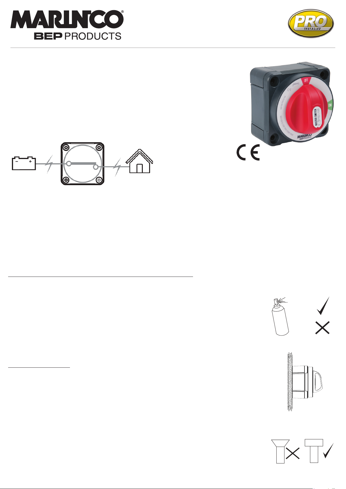
770 400A On/Off (Retail Packed)
770-B (Bulk Packed)
www.bepmarine.com | www.mastervolt.com | www.marinco.com
A powerful new generation battery switch with outstanding performance and features for both the
installer and end user. Three mounting options: surface, rear panel and front panel mounting, plus
optimised cable access makes installation a breeze. Pro installer switches set the new benchmark
with outstanding ergonomics. Intuitive look/feel and are engineered from the finest materials to with
stand the harsh marine environment.
Features & Benefits:
• Industry standard footprint
• Three mounting options – surface, rear-panel and front-panel
• Compatible with metric and imperial mounting fasteners
• User friendly design
• Removable knob for isolation/safety
• Includes back cover and three side panels for security and cable protection
• Designed to withstand harsh marine environments
• High temperature reinforced plastics
Specifications:
• Continuous rating: 400A
• Intermittent rating: 600A
• Cranking rating: 1500A
• Connection stud size: M10 (3/8”)
• 12-48V DC (Higher voltage applications on request)
• IP66 – protection from powerful water jets
• Ignition protected
• Independently tested to meet UL1107 standards
• CE
5 YEAR WARRANTY
Installation Instructions: IMPORTANT! Read before installing
• It is recommended that electrical terminations and connections are carried out by a marine electrical technician.
• Negative terminations, and Positive terminations must be to the same numbered studs i.e. both Negatives must be
connected to studs numbered “1”, or both Negatives connected to studs numbered “2”. Failure to do this will result
in short circuit or fire!
• These battery switches are for isolation purposes and are not designed for switching under load.
Ensure there are no circuits with high inductive loads directly connected to the switch in order to prevent any
sudden in-rush of current which may cause damage to the switch.
• Although specially selected chemical resistant materials have been used, we recommend that for maximum product
life only plastic safe corrosion inhibiting sprays are used.
• Ensure all cables are sized correctly for the loads they carry. Please refer to www.bepmarine.com to calculate
correct cable sizes.
• Ensure all electrical connections are correctly tightened to prevent any damage to the battery switch.
SURFACE
MOUNT
REAR
PANEL
MOUNT
FRONT
PANEL
MOUNT
Surface Mount Instructions
1. Choose mounting location on a flat surface close to the batteries
2. Select panhead (or similar) screws for mounting - use either M5 or 10g imperial (not included)
3. Knock or drill out plastic skin from screw holes in backplate
4. Select panhead (or similar) machine screws and nuts to secure switch to backplate - use either M6 x 40mm
or 0.25” x 1.5” (not included). Alternatively longer screws should be used if bolting all the way through the
bulkhead/surface
5. Place nuts for machine screws into nut recesses, then screw backplate into position
6. Connect cables to studs ensuring that batteries and loads are correctly fitted
7. Check that spring washers are fitted beneath nuts
8. Tighten the stud nuts to 13.5 Nm (10 lbf)
9. Slot the side panel(s) into the backplate as required
10. Clip battery switch and cable assembly into backplate
11. Secure switch in place with machine screws, engaging into nuts under backplate
12. Ensure cables are secured to ISO/ABYC standards, and that cables are supported so they are not placing
unnecessary strain on the battery switch studs (see diagram)
13. With switch in “OFF” position connect battery positive leads at battery
14. Check switch operation (as per reverse page)
T
O
R
Q
U
E
Plastic safe
Petroleum
based
solvents
T
O
R
Q
U
E
T
O
R
Q
U
E
Panhead
Cheesehead
Sockethead

Panel Mount Instructions
1. Choose mounting location
2. Ensure positive leads are removed from battery banks
3. Use the mounting template (shown below) to mark hole positions
4. Drill four machine screw holes and the 92mm (or 3 5/8”) hole for the switch body.
5. Front panel mounting only: either recess for the four clipping features (see template) or cut/file off these features from the
battery switch plate
6. Mount switch to panel using M6 (or ¼”) machine screws – note: use either pan or cheesehead screws only
7. Connect cables to studs ensuring that batteries and loads are correctly fitted
8. Check that spring washers are fitted beneath nuts
9. Tighten the stud nuts to 13.5 Nm (10 lbf)
10. Rear panel mounting only: back plate and side panels can also be clipped to the switch for cable protection/insulation
11. Ensure cables are secured to ISO/ABYC standards, and that cables are supported so they are not placing strain on the
battery switch studs (see diagram)
12. With switch in “OFF” position connect battery positive leads at battery
13. Check switch operation (as below)
Check switch operation:
a. Loads have no voltage in “OFF” position
b. Loads have voltage in “ON” position
Example System:
NOTE -This diagram is a guide only showing
On/Off Switch connections and is not intended as
a full electrical systems wiring diagram.
Mounting Template
Surface Mount Screw Holes
For Backplate
55.0 [2.17]
55.0 [2.17]
76.2 [3.00]
76.2 [3.00]
5.0 [0.20]
6.4 [0.25]
92.0 [3.62]
Use 3 5
8"
holesaw
47.7 [1.88] 13.9 [0.55]
30.4 [1.20]
97.8 [3.85]
91.9 [3.62]
38.0 [1.50] 53.9 [2.12]
Clipping feature:
• Either remove clipping
features or recess panel
when front panel mounting
Dimensions:
Loads
Engine
+
-
Optional Fuse
Mounting Template
Surface Mount Screw Holes
For Backplate
55.0 [2.17]
55.0 [2.17]
76.2 [3.00]
76.2 [3.00]
5.0 [0.20]
6.4 [0.25]
92.0 [3.62]
Use 3 5
8"
holesaw
47.7 [1.88] 13.9 [0.55]
30.4 [1.20]
97.8 [3.85]
91.9 [3.62]
38.0 [1.50] 53.9 [2.12]
Clipping feature:
• Either remove clipping
features or recess panel
when front panel mounting
SURFACE
MOUNT
REAR
PANEL
MOUNT
FRONT
PANEL
MOUNT
SURFACE
MOUNT
REAR
PANEL
MOUNT
FRONT
PANEL
MOUNT
Please check scale
before using
This manual suits for next models
1
Other BEP Marine Switch manuals


Popular Switch manuals by other brands

Pittway
Pittway System Sensor EPS40EXP Installation and maintenance instructions

3Com
3Com OfficeConnect 8 installation guide

URC
URC HomeSet C100 owner's manual

Black Box
Black Box SERVSWITCH KV3108SA-R4 Quick install guide

ITT
ITT neo-dyn 100p Installation and operation manual

Siemens
Siemens SIMATIC NET installation manual


